Motion Simulation of a Modular Robotic System Haruhisa KUROKAWA, Kohji TOMITA, Eiichi YOSHIDA, Satoshi MURATA and Shigeru KOKAJI Mechanical Engineering Laboratory, AIST, MITI Namiki 1-2, Tsukuba, Ibaraki 305-8564 Japan
[email protected]
Abstract We present a novel modular robotic system that has a capability of both reconfiguration and robotic motion. A simulator has been developed to graphically design the system configuration, the reconfiguration process and motion of a cluster of the modules. Some examples of processes programmed by a human operator and generated automatically are presented.
1
Introduction
Homogeneous reconfigurable robotic systems, which are composed of one kind of autonomous modules, have the various advantages compared with conventional mechanical systems. 1)Scale extensibility: A homogeneous system is capable of scale extension or contraction; the scale of the system can be changed by adding or removing modules. 2) Self repair: All the modules are the same, have the same functions, can be replaced by any other modules, and can reconfigure by themselves. Thus faulty modules can be removed from the system and the total system can be repaired. 3) Design freedom: One can freely build the system by connecting the units like LEGO blocks. 4) Adaptation: A reconfigurable system can change its configuration hence it can change its function depending on its task and the environment by itself.
serial link robots made of many joint modules. Although this type is suitable for generating robotic motion, it is difficult to reconfigure by itself. We have proposed a modular robotic system that has advantages of both types; capability of reconfiguration and generation of robotic motion [6 , 7]. For instance, a cluster of modules in lattice structure can construct a legged robot by reconfiguration, and then, it can walk with the legs. We developed a simulator for this system which provides interactive GUI to assist design process of reconfiguration. By using the simulator, reconfiguration planning and motion generation can be designed. In the following, we describe module design, a simulator, basic motions, and then show some examples of reconfiguration and motion.
2
Module Design
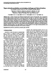
The robotic module we have proposed consists of two semi-cylindrical boxes, called box-part hereafter, and a link between them (Fig. 1). Owing to the semicylindrical shape, each box-part can rotate by 180 degrees. Two high-torque servomotors are embedded in the link to control the rotational angles. Connection face Link
Recently, many homogeneous reconfigurable robots have been studied. They can be classified into two categories: lattice type and linear type. The lattice type systems (e.g., [5 , 13 , 1, 10 , 4, 8]) are constructed by the modules in a lattice structure with some spatial symmetry, such as honey comb or jungle gym. This type is suitable to construct various static configurations, but difficult to generate group motion. The linear type systems (e.g., [12 , 2 , 11 ]) are basically
0-7803-6456-2/00/$10.00 ©2000 IEEE
2473
Permanent magnet Box part
Servo motor axis
Figure 1 Structure of module
Fig. 2 Prototype module Each box-part has three flat surfaces, called connection surfaces hereafter. Each connection surface can be connected to that of another module. Firm connection is realized by permanent magnets on each connection surface. At the same time, electricity supply and communication channel are connected. In order to reduce the force to detach the magnets, we adopt the idea of "Internally-Balanced Magnetic Unit" [3 ] using combination of nonlinear spring and SMA (shape memory alloy). Disconnection is made by supplying electric current to the SMA for some period of time. We developed the first prototype module (Fig. 2). The size of each semi-cylindrical box is inscribed in a 66 mm cube and each module weighs 400 g. Hardware design is detailed in [6 , 7 ].
3
Simulator
We have built an interactive simulation system of the modular system. This allows us to design a sequence of reconfiguration, and to give several motions to the modules. The simulator is developed on a PC with Windows 98/NT or on Linux using VC++/OpenGL or C++/ OpenGL/GLUT/MUI. Main functions of the simulator are: • Graphical display of the process. Motion of the modules is animated. • Graphical editing of initial configuration. • Graphical editing of the motion sequence. • Display of the modules’ state. • GUI facilities: including zooming in and out, changing the view point, and toggle change of visibility of other objects such as floors and walls.
Fig. 3 Simulator overview Figure 3 shows an example of operation after opening the program edit window. The state of the modular system is described by an array of all the modules' states. Each module is labeled by ID (0,...,n) and its two box-parts are labeled by 0 and 1. Each module's state is defined as a C++ class structure having members as the position and the orientation of the box-part-0 and two angles between the link and the box-parts. By using the editor of the simulator, an arbitrary initial configuration of any number of modules are graphically designed and then stored as a text file. A motion sequence is described by a series of motion steps, which are program statements of a kind of robot language. Available statements include change of two angles of a module, some predefined motion of a module, control command to connect/disconnect two adjacent box-parts, control command to synchronize several program steps and simple loop command without nesting. A program statement corresponding to a motion of a single module shown in Fig. 4 is coded as, “m 0 0 3 3”, where the first character is a mnemonic of the command of angle change, the 2nd and the 3rd numbers are module’s ID and box-part number, and remaining two numbers are quantized angles. We defined some predefined commands of motions for simplicity. The previous command example is also coded as “r 0 0”. For this motion in Fig. 4, other modules on the line are set facing their connection surfaces upward, so that the moving module can
2474
Fig. 4 Linear tranlation motion
Fig. 5 Preparation of connection surface connect its end to another module on the line and repetitive motion is possible. In the case in the left of Fig. 5, the tip of the moving module cannot connect to the module on the line. We have defined another predefined command, which moves a module to prepare for connection as shown in Fig. 5. This command is coded such as “b 1 0 0 0”. Actual motion to this command is designed as step-wise linear motion of angles in order to avoid collision with neighbor modules. The simulator checks whether all the modules can be connected but does not check whether each command motion cause collision between modules except in the above command. By using the simulator, a program is graphically designed and stored as a text file. Then, the simulator processes each program step at each "simulation time step", updates the states of modules and display the motion of modules as animation. Concurrent motions of multiple modules can be realized by several command statements put between synchronization commands.
4 4.1
Reconfiguration and Motion Procedure Basic Motions and Modes
Though each module has limited degree of freedom, a cluster of the modules has an ability of reconfiguration.
Three basic motions and two modes are introduced here to explain reconfiguration process. Here in the examples, we assume that the motions are carried out on a plane tiled by many other modules. The first basic motion is a forward roll motion explained previously by Fig. 4. It is a linear translation on a line, by which the module cannot change its direction. The planer motion of a single module (Fig. 6 (a)) is another basic motion by which the module traverses on the plane to any direction. These two situations define two modes of a module which are the relations of the module to a plane. The third basic motion by two modules enables a module either to change between these two modes (Fig. 6 (b)) or to change the direction of the linear translation mode. In Fig. 6 (b), the left module acts as a converter, and the right module's mode is converted. By combining these three basic motions, modules can reconstruct variety of structures. 4.2
Motion example
Examples of hand-coded reconfiguration processes are shown in Figs. 7 (a) and (b). In the first example (Fig. 7 (a)), a group of 18 modules gets over a wall by reconfiguration. It takes about 400 steps. In this procedure, two modules on the side of the cluster have a role of mode conversion. These two modules are necessary to change the mode of some modules. Without them, the cluster cannot change its direction and its mobility is highly restricted.
2475
(a) Planer motion
(b) Mode conversion Fig. 6 Basic motions
(a) Getting over a wall
(b) Legged walking Fig. 7 Example of reconfiguration The next example in Fig. 7 (b) is to realize a legged robot from a box shaped cluster. A cluster of 22 modules reconfigures itself into a legged robot of 12 modules after 80 steps, and then it begins a walking motion. Again, in the initial configuration, the cluster is composed of a main cluster of 20 modules and two modules in different mode at the side of the cluster.
The mode of the leg module is different from that of the main body in the initial configuration. Two modules placed on the side play a central role to change modes of some modules. Note that, in these two simulations, we do not assume the floor tiled by other modules.
2476
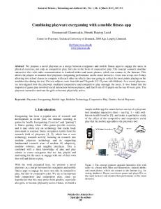
Fig. 8 Automatic rolling around a block 4.3
On Autonomous Reconfiguration
The example procedures in the previous section were designed by a human operator using the simulator. The next target is self-reconfiguration and automatic generation of motion. For instance, if we consider a fixed configuration of Fig. 7 (a), the previous motion can be extended in a straight forward manner to get over several walls in different size. If the initial configuration is different or the task is different, however, the design of reconfiguration process is not realized by a simple extension of such sample processes and is not easy to program even by a human operator. One example task we have realized is a rolling motion of two connected modules along the face of a block made of other modules. For this task, initial states of the two modules and configuration of other modules are supposed arbitrary. In Fig. 8, modules A and B try to roll around the rectangular block of other modules. First, neighborhood geometry of the surface of the block is examined in the range where two modules can reach. Second, motion of two modules are determined according to the geometry of the surface by using a predefined template of motions. In some cases, a module on which the end of the two moving modules will touch after the motion is not facing its
connection surface (C in Fig. 8 (b) and D in Fig. 8 (d)). In this case, this module must prepare its connection surface before the motion of the two moving modules (C in Fig. 8 (c)). After several motions, this surface becomes useless (C in Fig. 8 (f)), then the module of this surface is moved to become its original configuration (C in Fig. 8 (g)). The automatic motion planning including all the above processes was implemented and repetitive rolling motion was successfully realized for several configurations. Figure 8 (h) shows a program list made by a human operator corresponding to the same motions from Fig. 8 (a) to Fig. 8 (g) as a reference. This rolling motion is one of the simplest tasks of automatic motions. Even for this task, there remains some problems as follows: 1) We designed a template which maps geometry of the neighborhood surface to a motion of modules as a one-to-one mapping. By this one-to-one mapping, successful rolling motion cannot be defined for all the geometry. In some cases, the tip of two moving modules does not touch any other modules. Therefore, appropriate selection among various one-to-multi mappings and/or try and error process is necessary. 2) We supposed that the surface on the route of other modules is composed of either connectable surfaces or the modules' parts which can
2477
be moved to change their surfaces as connectable. If it is not the case, different kinds of motions are necessary to realize repetitive rolling motion. For complicated tasks such as reconfiguration from a given shape to an arbitrary shape, automatic process generation must be more difficult. There is no method even to know whether a given task is possible or not. Possible approaches might require definition of more meaningful macro sequences, tree searching or heuristics.
5 Conclusions We presented the novel modular robotic system that has capability of both reconfiguration and motion generation. A graphical simulator for this system has been developed and several complicated process has been planned using the simulator. Many future works are remaining. We are to conduct basic experiments of hardware modules to show the feasibility of the system. Six modules are currently being developed. All the modules have their own controllers which are connected to a broad casting network to a host computer. We believe it not difficult to modify the simulator to generate actual signals to these controllers according to the designed sequence. In terms of the simulator, we need to implement various tools for analysis, such as kinematics (collision detection and closed chain inverse-kinematics), statics (calculation of force and torque and stability analysis under gravitational force), and kinetics (calculation of dynamic force and torque). In the algorithmic side, self-reconfiguration and autonomous motion generation must be investigated, which takes into account not the exact configuration of modules but the function of module clusters such as a structure, locomotion, and manipulation. Autonomous and emergent methods should be investigated.
References [1] G. Chirikjian, A. Pamecha and I. Ebert-Uphoff, "Evaluating Efficiency of Self-Reconfiguration in a Class of Modular Robots," Journal of Robotic Systems, Vol. 13, No. 5, pp. 317-338, 1996. [2] G. Hamlin and A. C. Sanderson, Tetrobot; A Modular Approach to Reconfigurable Parallel
Robotics, Kluwer Academic Publishers, 1998. [3] S. Hirose, M. Imazato, Y. Kudo and Y. Umetani, "Internally-Balanced Magnetic Unit," Advanced Robotics, Vol. 3, No. 1, pp. 225-242, 1986 . [4] K. Kotay, D. Rus, M. Vona and C. McGray, "The Self-reconfigurable Robotic Molecule," Proceedings of the 1998 IEEE International Conference on Robotics and Automation, pp. 424431, 1998. [5] S. Murata, H. Kurokawa and S. Kokaji, "SelfAssembling Machine," Proceedings of the 1994 IEEE International Conference on Robotics and Automation, pp. 441-448, 1994. [6] S. Murata, E. Yoshida, K. Tomita, H. Kurokawa and S. Kokaji, "Self-Reconfigurable Modular Robotic System," Proceedings of International Workshop on Emergent Synthesis (IWES '99), pp. 113-118, 1999. [7] S. Murata, K. Tomita, E. Yoshida, H. Kurokawa and S. Kokaji, "Self-Reconfigurable Robot ~Module Design and Simulation~," submitted to the 6th International Conference on Intelligent Autonomous Systems (IAS-6). [8] D. Rus and M. Vona, "Self-reconfiguration Planning with Compressible Unit Modules," Proceedings of the 1998 IEEE International Conference on Robotics and Automation, pp. 2513-2519, 1998. [9] K. Tomita, S. Murata, H. Kurokawa, E. Yoshida, and S. Kokaji, "Self-assembly and Self-repair Method for a Distributed Mechanical System," IEEE Transactions on Robotics and Automation, Vol. 15, No. 6, pp. 1035-1045, 1999. [10] C. Ünsal, H. Kılıççöte and P. K. Khosla, "I(CES)cubes: A Modular Self-reconfigurable Bipartite Robotic System," Proceedings of the SPIE Conference on Sensor Fusion and Decentralized Control in Robotic Systems II, SPIE Vol. 3839, pp. 258-269, 1999. [11] P. Will, A. Castaño and W.-M. Shen, "Robot Modularity for Self-reconfiguration," Proceedings of the SPIE Conference on Sensor Fusion and Decentralized Control in Robotic Systems II, SPIE Vol. 3839, pp. 236-345, 1999. [12] M. Yim, "New Locomotion Gaits," Proceedings of the 1994 IEEE International conference on Robotics and Automation, pp. 2508-2524, 1994. [13] E. Yoshida, S. Murata, K. Tomita, H. Kurokawa and S. Kokaji, "An Experimental Study on a Selfrepairing Modular Machine," Robotics and Autonomous Systems, Vol. 29, No. 1, pp. 79-89, 1999.
2478