2011 IEEE International Conference on Robotics and Automation Shanghai International Conference Center May 9-13, 2011, Shanghai, China
A New Self-Reconfigurable Modular Robotic System UBot: Multi-mode locomotion and Self-reconfiguration Jie Zhao, Xindan Cui, Yanhe Zhu, Shufeng Tang
Abstract—In the paper, a concept of novel self-reconfigurable robotic system made of the autonomous robotic modules has been reviewed. Each robotic module is made of simple structure and few degrees of freedom; however, a group of the modules is able to change its connective configuration by changing their local connections and has functionality of robotic system which is capable of generating complicated motions and accomplishing a large variety of tasks, such as: transportation, exploration, inspection, construction and in-situ resource utilization. Multimode locomotion and self-reconfiguration are the basic and essential abilities for the self-reconfigurable robotic system. Based on this concept, a new self-reconfiguration system, UBot robotic system that combines the advantages from the chain-based and lattice-based robots has been proposed. Each UBot module which is cubic structure based on universal joint has two rotational DOF and four connecting surfaces that can connect to or disconnect from adjacent modules. The smart structure and the reliable connecting mechanism of the modules make the robot flexible enough to complete multimode locomotion and self-reconfiguration. This paper demonstrates the design philosophy of the UBot module and a solution for multimode motions and self-reconfiguration using the UBot system. The system can complete motion in the modes of quadruped, chain and loop configuration. Besides, the system can deform from one mode to the other though self-reconfiguration. All the proposed methods have been verified though simulations and real hardware experiments.
I
I. INTRODUCTION
N recent years, a modular robotic system composed of reconfigurable units has been an active area of research. The concept of the modular self-reconfigurable system is to have a collection of simple robotic modules that can attach and detach from each other to form structures that best meet the challenges of the robot’s current environment and task. Existing reconfigurable robots can be mainly classified into two categories: the lattice-based and the chain-based reconfigurable robots. The module of a lattice-based robot
Manuscript received September 15, 2010. This work was supported in part by the National Natural Science Foundation of China (Grant No. 60705027). Jie Zhao is with the State Key Laboratory of Robotics and System, Science Garden of HIT, NO.2, Street YiKuang, District NanGang, Harbin, China. 150080 (fax: 045186414538; e-mail: jzhao@ hit.edu.cn). Xindan Cui is with the Room 203, Building C1, State Key Laboratory of Robotics and System, Science Garden of HIT, NO.2, Street YiKuang, District NanGang, Harbin, China. 150080 (phone +8615846587294; e-mail:
[email protected]). Yanhe Zhu is with the State Key Laboratory of Robotics and System, Science Garden of HIT, NO.2, Street YiKuang, District NanGang, Harbin, China. 150080 (e-mail:
[email protected]). Shufeng Tang is with the State Key Laboratory of Robotics and System, Science Garden of HIT, NO.2, Street YiKuang, District NanGang, Harbin, China. 150080 (e-mail:
[email protected]).
978-1-61284-385-8/11/$26.00 ©2011 IEEE
[1]-[11] is designed to reach only its adjacent modules. Such a design makes reconfiguration simple but locomotion more difficult. The lattice architecture demonstrate locomotion through “flow” its modules on top of each other one by one, which makes the locomotion complex and slow. On the other hand, the chain-based robots [12]-[14] can bend themselves in coordination to move in the whole body locomotion, but the underlying architecture is serial. Through articulation, chain architectures can potentially support efficient gaits and offer flexible reconfigurations, but it is computationally more difficult to represent and analyze and more difficult to control. To combine the advantages of the lattice-type and chain-type systems, the hybrid-type reconfigurable robots have been invented. M-TRAN modular robot system [15][16] is the first hybrid-type reconfigurable robot. The module is made up of two U-shape blocks connected by a link rod. Each block has one DOF by connecting with the link rod. But the two degrees of freedom are in the same direction; therefore, the module can only rotate in one plane. SuperBot [17], [18] module has been proposed on the basis of M-TRAN modules. Each SuperBot module has three joints, which is more flexible for locomotion, but the connecting mechanism is not yet perfect, the modules should be connected to each other manually. The UBot [19] module described in this paper based on the universal joint is of cubic shape with two rotational joints and reliable active connecting mechanism, which is quite suited for locomotion and self-reconfiguration. This paper is organized as follows. Section 2 introduces the design philosophy of the UBot module and simply describes the UBot system hardware. Section 3 presents a set of multimode locomotion configurations composed of our UBot modules. The characteristics and gaits of each locomotion configuration have been described in detail in the subsections of section 3. Hardware experiments have been done for each modes. Section 4 describes the self-reconfigurable ability of the UBot system. A necessity criterion and a deformation plan method based on the UBot robot have been proposed. Results of simulation and hardware experiment are also provided. Conclusions and the future work are given in section 5. II. UBOT MODULE HARDWARE The module is the elementary unit of the SR robot system. To provide the needed flexibility for the multimode locomotion and self-reconfiguration, the modules should be regular and smart in size and mass, at the same time, should
1020
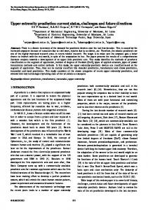
have one or more degrees of freedom. The UBot modules described in this paper integrate all the aspects mentioned above. Each UBot module is cubic structure based on universal joint and has two rotation joints and four connecting surfaces, as shown in fig.1. The module is composed of two parts P10 and P00, which can rotate from -90°to 90°around independent joints J10 and J00 respectively. All possible joint states of the module are shown in fig.2.
directions.
a) Active module b) Passive module Fig.3. UBot modules
Fig. 1. Concept of the UBot module a) Active connecting mechanism b) Passive connecting mechanism Fig.4. Connecting mechanism
The connecting mechanism has the function of self-lock and energy-saving and can connect to or detach from the adjacent modules quickly and reliably. The mutually opposite polarity of the permanent magnets located on the surface of each connecting surface provides pre-position for the connecting. The connecting mechanism and the module substrate have been connected with full contact connection, so the maintenance of the modules is more convenient. The battery is embedded inside the module, and the wires go through the center of the right angle shaft between two parts to solve the problem of the cable wound, so the module is compact. The details of the mechanism design and performance have been described in [18]. Fig. 2. Joint states of the module for self-reconfiguration process
Fig.3 and tableI have introduced the real UBot modules and the performance parameters. There are two types of the UBot modules: active module and passive module. TABLEI SPECIFICATION FOR UBOT MODULES
Dimension (mm×mm×mm) Active module Weight (g) Passive module Load weight ratio Connecting / Detach time (s) Maxium communation radius (m)
80×80×80 350 280 4 0.5 250
Fig. 5. UBot system
Connections can only happen between the active module and passive module. The active and passive hook-type connecting systems have been proposed and embedded in the active and passive modules respectively, as shown in fig.3. There are four radially placed slots on both the active and passive connection surfaces. The active connection surface also has four connecting hooks, while the passive one has nothing. The rotational symmetry of the connecting mechanism allows the surface to connect to each other in four
The UBot system is composed of a host computer, a relay unit and UBot modules, as shown in fig.5. The system can simulate and control the modular robots complete multimode locomotion and self-reconfiguration. III. MULTI-MODE LOCOMOTION One of the key features for the UBot robots is feasible enough to support many different locomotion modes on a wide range of terrain types, because a robot may travel
1021
through terrains that may not be fully characterized ahead of time to accomplish a large variety of tasks, such as transportation, assembly, inspection and exploration. For example, a robot must be small and flexible in the inspection, must “climb” in going up a slope, must “run” if it is escaping the chase, and must “creep” in going through a hole. The UBot modules can compose different motion configurations to satisfy different terrains. In next subsections, several representative locomotion modes will be introduced in detail. A. Snake-type mode The snake-type configuration is very popular in the SR system research area. This configuration is easily extended to an arbitrary number of modules without complicated control. Because each UBot module has two rotational joints: horizontal to the ground and vertical to the ground, the joints of the snake-type configuration has been divided into two groups: horizontal joints to control the direction, vertical joints to generate the forward locomotion. The motion type of the chain-type configuration is multiple. Fig.6 shows the forward worming gait, which is achieved by propagating a waveform traveling down the length of the chain. The waveform can be various, we used here is a joint-space sinusoid waveform.
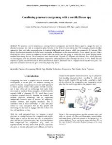
constrained terrains. Besides, it can also go through the narrow crack or tube. B. Quadruped-walker mode In many cases, terrain to be traversed is highly irregular and has many obstacles that are of size comparable to that of the robot itself. At this time, the snake-type configuration becomes impossible, and then limbed morphology has to be used to allow for “walking”, “climbing” and similar gaits. The limbed-type configuration has lots of advantages, and should be an important configuration of our UBot system. In this paper, we emphasize on the quadruped configuration. The quadruped configuration we studied has 13 modules. It is composed of three modules for each legs and a single module representing the torso as seen in fig.8. The four modules which are adjacent to the torso module connect with the other modules vertically; therefore, each leg has one freedom to change its orientation from -90° to 90°. The configuration is entirely symmetry. We marked the legs as LF, RF, RB, LB for convenience.
Fig. 8. Quadruped configuration in locomotion mode
Fig. 6. Worming gait
The worming gait mentioned above only uses each module’s vertical rotational freedom. The configuration can move along a circular arc for tuning left or right by adjusting the horizontal joints to an fixed angle.
Each leg has six rotational freedoms, so it is flexible enough to lift forward or lateral. That makes the quadruped configuration have the ability to travel across the rough terrains. More importantly, this quadruped configuration can use one of its leg as the operating arm when the other three legs supporting the whole body. Take leg RB as the example, it can hold up and reach the top of the construction to pick up tools or manipulate. Fig.9 shows the configuration in operating station.
Fig. 9. Quadruped robot in operating mode Fig. 7. Wriggling gait
In the snake-like wriggling gait, two sinusoid waveforms have been used to control the vertical and the horizontal joints respectively. As fig.7 shows, the gait is like a serpentine snake, which verifies the flexibility of the configuration. This snake-type configuration can make use of its low height property to stabilize it on the slope and other highly
A group of locomotion experiments using the quadruped configuration have been completed, that is: crawling gait and turning gait. Fig. 11 shows the crawling walking gait, which is much more similar with the real reptiles. The robot bent over on the floor in the beginning. When the motion starts, four legs stand up together to lift up the whole body, the legs then take turns
1022
to stride in the sequence of LB→LF→RB→RF, as shown in fig.10. The bold lines in the picture represent the current state in each step. The four legs move in the loop of A→B→C→D→A, in which A→B, B→C, C→D are attitude adjustment stages, D→A is the walking stage. The configuration moves forward S distance after one period. The robot maintains its balance across the striding process, because in the whole process the projection of the gravity center is in the range of the other three supporting legs. The robot has walked 600mm in 10s steadily.
LF→LB→RB→RF. There are four striding steps and two attitude adjusting steps in one period. The turning gait has been verified through the experiment (as shown in fig.13). In the experiment, we demonstrated the gait intermittent turning around its own center. The robot has turned 180° in 17s steadily.
Fig. 13. Turning motion experiment of quadruped configuration
C. Loop-type mode The loop-type mode rolls like a tread. Just as a wheeled style of motion, this mode tends to be more energy efficient than the other motion modes. This configuration is well suited to move on straight, flat terrain and even climb or roll down some small slope terrain.
Fig. 10. Crawling gait of quadruped robot.
Fig. 14. Distribution of degrees of freedom for loop configuration Fig. 11. Crawling experiment of quadruped configuration
The quadruped configuration is one omni—directional motion structure. The robot can turn in the process of walking, and the anticlockwise turning gait is shown in fig.12.
Loop configuration is composed of several couples of modules (one active module and one passive module), because an active module can only be connected to a passive module in the connection mechanism of the UBot system. Limit to the module’s shape and the rotation angle of the joints, at least 6 modules are needed to compose a loop configuration which has the locomotion ability. In this paper, we emphasized on the loop configuration which consists 12 modules, as shown in fig.14. The motion plan refers to reference [23].
Fig. 15. Model of dynamic rolling
Fig. 12. Turning gait of quadruped configuration
The bold lines in the picture represent the current state in each step. The robot strides in the sequence of 1023
Through changing the loop’s shape, the robot can roll on
the floor. To accelerate the rolling velocity, we could make the center of gravity stand in front of the support range of the configuration in the rolling process that is what we called dynamic rolling gait. We choose the loop shape of the rolling as an American football, as shown in fig.15.
has been proposed. The criterion is: min( naIC , npIC ) ≥ min(naGC , npGC ) ⎫ ⎬ max( naIC , npIC ) ≥ max(naGC , npGC ) ⎭
Where IC represents the original configuration, naIC and npIC represents the quantity of active modules and passive modules in IC respectively; GC means the target configuration, naGC and npGC represents the quantity of active modules and passive modules in GC respectively. The criterion can remove a portion of configuration couples which can’t be deformed to each other, and avoid the meaningless operation of the deformation. The criterion can also be applied to other SR robot system the modules of which are cubic and only have rotational degrees of freedom. For the reconfiguration between the fixed configurations, a deformation planning method that makes the degree of the configuration similarity as the search-driven function has been proposed according to the literature[19~21]: σ s ( IC , GC ) =
Fig. 16. Dynamic rolling process of typical loop configuration
Fig.16 shows the process of the dynamic rolling gait. There are 2 phases in the dynamic rolling process: first, the robot changes the loop’s shape to increase the distance from the center of gravity to the ground, as shown in fig.16(a-c); second, the robot falls like an inverted pendulum which hinged on the support point, as shown in fig.16(d-f). Fig.17 shows the experiment result of the dynamic rolling with 8 modules. The configuration has rolled 1200mm in 6s.
(1)
∑ min(C
R
( IC ), C R (GC ))
(2)
max( IC , GC )
Where σ s ( IC , GC ) represents the similarity degree between IC and GC, IC , GC are the edge number in IC and GC respectively. CR ( IC ), CR (GC ) are the quantities of R-connected modes in IC and GC respectively, of which, R represents any kind of 64 connection ways between the two modules. The method can find a deformation path which needs a relatively less steps within a reasonable time. The method has been used in the deformation from the four-limbed configuration to the snake-like configuration composed of the UBot modules and has been verified through the simulation, as shown in fig.18. There are 3 connection steps, 3 detaching steps and 26 times joint rotations in the whole reconfiguration. Conversely, the snake-type configuration can deform to the four-limbed configuration in the reverse sequence
Fig. 17. Dynamic rolling experiment of loop configuration
a)
b)
c)
d)
e)
f)
IV. SELF-RECONFIGURATION The restrictions in the process of self-reconfiguration of the UBot system have been analyzed. According to the characteristic of the UBot module, a few hypotheses have been proposed: 1. The information of the original configuration and the target configuration is given. 2. The deformation is performed on the level surface without any obstacles. 3. In each step, only one module executes the action, and one module can at most drive two modules to move with it. Therefore, a necessity criterion which can judge whether the configurations can be reconstructed between each other
Fig. 18. Reconfiguration process from four-limbed configuration to snake-type configuration
Furthermore, we performed the self-reconfiguration experiment from three-limbed configuration to snake-type configuration on the real UBot system. The experiment demonstrated the self-reconfigurable ability and wireless communication function, at the same time, verified the flexibility of the connecting mechanism. Fig.19 shows the
1024
self-reconfigurable process. There are four connecting actions and four detaching actions happened in the deformation process.
[7]
[8]
[9]
[10] Fig. 19. Reconfiguration experiment of UBot system [11]
V. CONCLUSION UBot, a new self-reconfigurable modular system has been presented. The design philosophy and the real UBot module based on the universal joint have been simply introduced. The module we invented is compact, smart and flexible. Then this paper mainly describes the two basic applications of the UBot system, multi-mode locomotion and self-reconfiguration through simulation and real hardware experiments. To the best of our knowledge, it is quite difficult for a conventional robot to achieve multi-mode locomotion and deformation. However, the UBot system can accommodate different locomotion modes and self-reconfiguration without increasing the hardware complexity of the robots; therefore, the system can avoid the inescapable tradeoff between the generality for adaptation and the specialty for high-performance for conventional robotic systems. In the future, we plan to add some sensors in the modules; therefore, the system can perceive external environment information in real time and make decision about which motion modes to choose and whether to deform. We also plan to add some assistant modules, such as: grabbing device or other execution modules to assist the system completing more tasks in real application.
[12]
[13] [14]
[15]
[16]
[17]
[18]
[19]
REFERENCES [1]
[2]
[3] [4] [5] [6]
Amit Pamecha, Chih-Jung Chiang, David Stein et al, “Design and Implementation of Metamorphic Robotics,” in Proceedings of 1996 ASME Design Engineering Technical Conference and Computers in Engineering Conference, Irvine California, Aug. 1996, pp: 1-10. E.Yoshida, S. Murata, A. Kamimura et al, “Get Back In Shape! A Hardware Prototype Self-Reconfigurable Modular Microrobot that Uses Shape Memory Alloy,” IEEE Robotics & Automation Magazine, vol. 9, no. 4, pp: 54-60, 2002. Zack Butler, Robert Fitch, Daniela Rus, “Experiments in Distributed Control for Modular Robots,” Experimental Robotics VIII, Vol. 5, pp: 307~316, 2003. K. Kotay, D. Rus, M. Vona et al, “The self-reconfiguring robotic molecule,” in IEEE International Conference on Robotics and Automation, Leuven, Belgium, May 1998, pp: 424-431. Cem Ünsal, Han Kiliççöte, Pradeep K. Khosla, “A Modular Self-Reconfigurable Bipartite Robotic System: Implementation and Motion Planning,” Autonomous Robots, vol. 10, no.1, pp: 23-40, 2001. John W. Suh, Samuel B.Homans, Mark Yim, “Telecubes: Mechanical Design of a Module for Self-Reconfigurable Robotics,” in Proceeding
[20] [21] [22] [23]
1025
of the 2002 IEEE International Conference on Robotics and Automation, Washington, DC. May 2002, pp: 4095-4101. M. Bordignon, K. Stoy, U.P. Schultz, “A Virtual Machine-based Approach for Fast and Flexible Reprogramming of Modular Robots,” in Proceedings of the IEEE International Conference on Robotics and Automation 2009, Kobe, Japan, pp: 3792-3799. V. Zykov, E. Mytilinaios, B. Adamsand et al., “Self-reproducing machines: A set of modular robot cubes accomplish a feat fundamental to biological systems,” Nature, vol. 435, no. 7039, pp: 163-164, May 2005 Alexander Spröwitz, Soha Pouya, Stéphane Bonardi, Jesse van den Kieboom, Rico Möckel, Aude Billard, Pierre Dillenbourg, Auke Jan Ijspeert, “Roombots: Reconfigurable Robots for Adaptive Furniture,” IEEE Computational Intelligence Magazine, vol. 5, no. 3, pp: 20-32, 2010. A. Sproewitz, A. Billard, P. Dillenbourg et al, “Roombots-Mechanical design of Self-Reconfiguring modular robots for adaptive furniture,” in 2009 IEEE International Conference on Robotics and Automation, Kobe, Japan, May 2009, pp: 4259-4264. Fei Yanqiong, Zhang Xin, Xia Zhenxing, “Motion Spaces and Self-morphing Algorithm of Self-reconfigurable Modular Robot,” Journal of mechanical engineering (in Chinese), vol. 45, no. 3, pp: 197-202, March 2009. Rico Moeckel, Cyril Jaquier, Kevin Drapel et al, “Exploring adaptive locomotion with YaMoR, a novel autonomous modular robot with Bluetooth interface,” Industrial Robot, vol. 33, no. 4, pp: 285-290, 2006. M. Yim, D.G. Duff, K.D. Roufas, “PolyBot: a Modular Reconfigurable Robot,” in Proceedings of the 2000 IEEE International Conference on Robotics and Automation, San Francisco, CA, April 2000, pp: 514-520. M. Yim, B. Shirmohammadi, J. Sastra et al., “Towards Robotics Self-reassembly After Explosion,” in Video Proc. of the IEEE/RSJ Intl. Conf. on Intelligent Robots and Systems (IROS), San Diego CA, 2007, pp: 2767 – 2772. H. Kurokawa, K. Tomita, A. Kamimura et al., “Distributed Self-Reconfiguration of M-TRAN III Modular Robotic System,” The International journal of Robotics Research, vol. 27, no. 3-4, pp: 373-386, March 2008. A. Kamimura, S. Murata, E. Yoshida, H. Kuraokawa, K.Tomita, S. Kokaji, "Self-reconfigurable modular robot: experiments on reconfiguration and locomotion,” in Int. Conf. on Intelligent Robots and Systems, Maui, USA, Oct.2001, pp: 606-612., W.M. Shen, M. Krivokon, H. Chiu et al., “Multimode locomotion via SuperBot Robots,” in Proceedings of the 2006 IEEE International Conference on Robotics and Automation, Orlando, Florida, May 2006, pp: 2552-2557. B. Salemi, M. Moll, W.M. Shen., “SUPERBOT: A Deployable, Multi-Functional, and Modular Self-Reconfigurable Robotic System,” in Proceedings of the 2006 IEEE/RSJ International Conference on Intelligent Robots and Systems, Beijing, October 2006, pp: 3636-3641. Shufeng Tang, Yanhe Zhu, Jie Zhao, Xindan Cui, “The UBot Modules for Self-Reconfigurable Robot,” in ASME/IFToMM International Conference on Reconfigurable Mechanisms and Robots, London, 2009, pp: 529-535. X. Jiang, H. Bunke, “Optimal quadratic-time isomorphism of ordered graphs,” Pattern Recognition, vol. 32, no. 7, pp: 273–1283, 1999. John W. Raymond, Eleanor J. Gardiner, Peter Willett, “RASCAL: Calculation of Graph Similarity using Maximum Common Edge Subgraphs,” The Computer Journal, vol. 45, no. 6, pp: 631–644, 2002. M. R. Garey, D. S. Johnson, Computers and Intractability: A Guide to the Theory of NP-Completeness, San Francisco: W. H. Freeman, 1979. J. Sastra, S. Chitta, M. Yim, “Dynamic Rolling for a Modular Loop Robot,” The International Journal of Robotics Research, vol. 28, no. 6, pp: 758–773, June 2009