Int J Interact Des Manuf (2007) 1:175–179 DOI 10.1007/s12008-007-0020-6
SHORT ORIGINAL PAPER
A multi-disciplinary distributed simulation environment for mechatronic system design enabling hardware-in-the-loop simulation based on HLA Satoshi Kanai · Taku Miyashita · Tatsumi Tada
Received: 22 September 2006 / Revised: 10 October 2006 / Accepted: 17 October 2006 / Published online: 23 May 2007 © Springer-Verlag France 2007
Abstract This paper proposes a high-level architecturebased multi-disciplinary distributed simulation environment for designing mechatronic systems. In the system, commercial off-the-shelf simulators can communicate each other via real-time-infrastructure to realize software-in-the-loop simulation. Moreover, hardware prototypes can also participate in a part of the distributed simulation environment which enable us hardware-in-the-loop simulation. Effectiveness was verified by applying the environment to mechatronic system design of an automotive power-window and an omni-directional electric wheel chair. Keywords Mechatronic system design · High-level architecture (HLA) · Hardware-in-the-loop simulation · Multi-disciplinary simulation 1 Introduction Recently many mechatronic systems become wide spread ranging from industrial equipments to home electrical appliances, and there is a strong need for digital prototyping which can predict performances of the systems. However, in general, mechanical, electrical and control software divisions S. Kanai (B) · T. Miyashita Graduate School of Information Science and Technology, Hokkaido University, Kita-14, Nishi-9, Kita-ku, Sapporo 060-0814, Japan e-mail:
[email protected] T. Miyashita e-mail:
[email protected] T. Tada Hokkaido Industrial Research Institute, Kita-19, Nishi-11, Kita-ku, Sapporo 060-0819, Japan e-mail:
[email protected]
separately take charge of the design of the mechatronic systems, and the simulation of the system is still limited to a subsystem level in each of these divisions. To solve the problem, the purpose of this paper is to propose a multi-disciplinary distributed simulation environment for mechatronic system design based on the high-level architecture (HLA) [1]. In the proposed environment, commercial-off-the-shelf simulators of mechanical, electrical and control systems can be communicated with each other using a HLA compliant middleware to realize software-in-the-loop simulation (SILS) [2]. Moreover, to expand the range of supporting designers, we develop a function which allows hardware prototypes to participate in the multi-disciplinary simulation in the same environment to realize hardware-in-the-loop simulation (HILS). We applied the environment to the design of two mechatronic systems including HILS; an electric wheel chair system and an automotive power-window system.
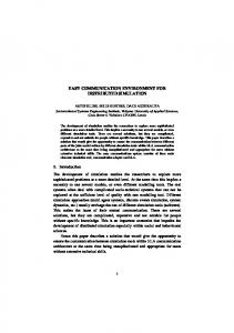
2 Application of HLA to multidisciplinary simulation of mechatronic systems The high-level architecture is the IEEE standard for the framework of distributed simulation [1]. As shown in Fig. 1, in the HLA, a middleware called run time infrastructure (RTI) provides basic communication functions among distributed simulators. Each simulator is called “federate” in the HLA. The data model of information exchanged among federates is pre-defined as a collection of classes and their attributes in Federation Object Model (FOM). However, to make commercial off-the-shelf simulators for mechatronic design HLAcompliant, data model of information exchanged among simulators have to be defined first in a FOM, and the RTI interface (RTI-I/F) has to be coded every time in the simulators in adhoc way depending on each system to be designed. But these
123
176
S. Kanai et al.
Federation
FOM (Federation Object Model) Sensor
Switch-On
•Voltage •Distance
Federate 1
Federate 2
Federate n
Simulation Engine
Simulation Engine
Simulation Engine
API
API
FedCode
FedCode
LRC
Sensor 1 •Voltage •Distance
API
FedCode
LRC
LRC
RTI I/F Code
Switch-On
RTI (Run-time Infrastructure)
Fig. 1 High-level architecture (H L A) framework
works make the lead-time of multi-disciplinary simulation very inefficient. To solve these problems, the following methods are proposed in this research to make simulators for mechatronics system design HLA-compliant. First, we propose a MechaFOM (mechatronics FOM) which standardizes a data model of SILS for mechatronic system design. Second, we also develop a hardware interface federate (HIF) which is a specialpurpose federate acting as an interface between the hardware prototype and the existing federates for enabling HILS.
3 FOM design specialized for mechatronic system simulation Mecha-FOM is our proposed FOM which is a collection of classes specialized for data of multi-disciplinary simulation an for mechatronic system design. In the design of Mecha-FOM, we considered following two requirements. First, the model should consist of notions usually shared among mechanical, electrical and control software simulation models. For this requirement, we define class structures in the Mecha-FOM based on notions of sensors and actuators. Second, the model should express the model of sensors and actuators in different level of detail which can be used both at initial and detailed design stages. For this requirement, we included both “Abstract FOM” and “Detailed FOM” in the Mecha-FOM specification. The Abstract FOM mainly consists of two classes which directly represents a continuous and discrete state variable. These variables are directly exchanged between federates in simulations at early design stage. On the other hand, Fig. 2 shows a class structure of the Detailed FOM. The model mainly consists of class hierarchies of sensors and actuators.
123
Figure 2a shows a class hierarchy of sensors. The children classes are classified based on physical quantities measured in the sensor such as length, angle, velocity, revolution, current and voltage, etc. The measured quantity is described in the attributes of each children class. Figure 2b shows a class hierarchy of actuators. The children classes are classified based on bond graph concept. In the bond graph [3], an actuator is modelled as a “power transformer” where one kind of power is converted into the mechanical power, and a power can be expressed as a product of a flow variable and effort variables. Therefore, flow (velocity or angular velocity) and effort (force and torque) variables of output mechanical power are described in attributes of the first-level subclasses. And flow (current, flow rate, etc.) and effort (voltage, pressure, etc.) variables of input powers are described in attributes of the second-level subclasses. We have already implemented functions of RTI-I/F corresponding to mechanical sensor classes, and linear and revolution actuator classes of the Mecha-FOM in a 3D-CAD system (CATIA) and a control simulator (Matlab). Concrete sensors and actuators used in a mechatronic system are defined as instances of these classes.
4 Hardware interface federate for HILS With progress of the system development, hardware prototypes of mechanical, electrical or control systems may be produced. More realistic simulation results could be obtained if these hardware prototypes join in multidisciplinary simulation and realize a HILS. For this purpose, we develop a hardware interface federate (HIF). The HIF is an interface federate between hardware prototypes and existing federates. It enables designers to smoothly make a transition from SILS to HILS. Figure 3 shows the structure of the HIF. It bridges between objects defined in the Mecha-FOM and hardware interface device such as A/D and D/A converters and digital input/ output boards. Functions of the HIF are defined by three models; hardware interface model, federation object meta-model and mapping rule model. The hardware interface model describes signal specifications of the interface device such as number of channels, sampling rate, range of signal and signal resolutions. The federation object meta-model describes objects (instances) of the Mecha-FOM used in the simulation. The mapping rule model describes a set of mapping rule from a signal of the hardware interface device to an attribute of objects of the Mecha-FOM. The contents of the three models are defined in an external XML file, and the HIF software reads it before running. Therefore, if the specification of the hardware interface device changes, we only have to rewrite data in the XML file, and code of the HIF software remain unchanged.
A multi-disciplinary distributed simulation environment for mechatronic system design
177
Fig. 2 Structures of Detailed FOM (UML class-diagram)
5 Application of HLA-based SILS and HILS to design of a wheel chair’s motion control system
Fig. 3 Structure of hardware interface federate (H I F)
The multi-disciplinary simulation environment was applied to both SILS and HILS of the motion control system design of an omni-directional electric wheel chair. The chair has four mechanum wheels [4], and driving different velocities to the four wheels enables omni-directional movement of the chair. Three D.O.F. joystick displacement signals from a passenger have to be converted into four motor signals controlling angular velocities of each wheel in the motion control system. Figure 4 shows a multidisciplinary simulation environment developed for this design. One SILS and two HILS were progressively executed shown in the figure. First, as the SILS of Fig. 4a, we combined a control system simulator (Simulink) with a mechanical system simulator (VRML-viewer) by using a commercial RTI (MAK-RTI) [5]. An initial directional control algorithm of the control system was verified, and an optimum dead zone for a joystick signal
123
178
S. Kanai et al.
Control system simulator (Matlab)
Mechanical system simulator (VRML viewer)
(a)SILS (a)SILS MechaFOM RTI-I/F RTI-I/F
RTI-I/F RTI-I/F
RTI (MAK(MAK-RTI) HIF HIF
Joystick
HIF HIF
(c)HILS (c)HILS
(b)HILS (b)HILS Mechanum wheels Micro-controller (ADuc 7026)
Wheel chairmechanism
Fig. 4 Multi-disciplinary SILS and HILS for wheel chair’s motion control design
Fig. 5 Multi-disciplinary SILS using detailed FOM for power window control design
123
A multi-disciplinary distributed simulation environment for mechatronic system design
could be iteratively found to avoid chattering using the SILS. Second, as the HILS of Fig. 4b, we exchanged the mechanical system simulator for a real wheel chair by installing a HIF running on the portable computer on the chair. Acceleration and deceleration are subjectively evaluated by a passenger to provide maximum riding comfort. Finally, as another HILS of Fig. 4c, we exchanged the control system simulator for a microcontroller (ADuc7026) by installing a HIF in which a manually-programmed control code made from the simulation model was embedded. The correctness of the embedded code was verified in the HILS. The latency of communication on HLA was several milliseconds, and did not affect the performance of HILS in this case study. As a result, ergonomic and safety design of the control system for this wheel chair was streamlined.
6 Application of HLA-based SILS to design of a automotive power window control system As another example, safety design of automotive power window control system was done using two kinds of the SILS. The objectives of the design are to verity correctness of state-transition discrete control logic for opening and closing windows, especially of the special fail-safe logic to avoid pinching accidental in the window. For the SILS, we combined a control system simulator (Simulink/Stateflow) which simulates discrete control logic of the window drive with a 3D kinematic simulator (CATIA) of window mechanism. In the initial SILS, an abstract FOM was used to define data exchanged between the control system simulator and the kinematic simulator. On the other hand, in the final SILS, as shown in Fig. 5, a motor attached
179
to a joint of the link mechanism of the window and a rotational sensor attached to a link are modelled in a detailed FOM. The voltage of the motor and the detected angle of the rotational sensor were exchanged. In this SILS, the fail-safe control logic was easily verified by placing a 3D model of the obstacle in the window and by observing motion of the glass.
7 Conclusions A multi-disciplinary distributed simulation function for mechatronic system design based on the HLA was developed. It allows designers of mechatronic systems to evaluate not only the virtual prototype of the system but the physical prototypes by combining SILS and HILS on a uniform software environment. Experimental studies indicated a sufficient potential of an application of HLA to ergonomic and safety mechatronic system design and simulation.
References 1. IEEE (ed.): Standard for Modeling and Simulation (M and S) High Level Architecture (HLA). 1516 (2000) 2. Kanai, S., Tada, T.: Multi-disciplinary distributed simulation for designing it devices by integrating off-the-shelf cax systems based on hla. In: Proceedings of Fall 2004 Simulation Interoperability Workshop, pp. 315–325 (2004) 3. Gawthrop, P., Smith, L.: Metamodelling: Bond Graphs and Dynamic Systems. Prentice-Hall, Englewood Cliffs (1995) 4. Wada, M.: Omni-directional control of a four-wheel drive mobile base for wheelchairs. In: Proceedings of IEEE Workshop of Advanced Robotics and its Social Impacts, pp. 195–201 (2005) 5. Mak hla/dis toolbox for matlab and simulink. http://www.mak.com/ toolbox.php
123