In this paper we introduce Farm, a distributed simulation environment ... Air Force Research Laboratory Air Force Materiel Command, USAF, under ...... determine their individual performance metrics by computing a common benchmark.
The Farm Distributed Simulation Environment Bryan Horling, Roger Mailler, Victor Lesser Multi-Agent Systems Lab University of Massachusetts Amherst, MA 01003-9264 bhorling,mailler,lesser�@cs.umass.edu
Abstract. In this paper we introduce Farm, a distributed simulation environment for simulating large-scale multi-agent systems. Farm uses a component-based architecture, allowing the researcher to easily modify and augment the simulation, as well as distribute the various pieces to spread the computational load and improve running time. Technical details of Farm’s architecture are described, along with discussion of the rationale behind this design. Performance graphs are provided, along with a brief discussion of the environments currently being modeled with Farm.
1 Introduction A tension exists in simulation frameworks which trades off the inherent richness of the provided environment, and the flexibility and ease with which that same environment can be used to analyze a particular aspect of a larger solution. On one hand, robust simulation environments can offer many enabling technologies that both increase the fidelity of the simulation, and provide a range of services that the participants may use to their advantage. These same features, however, can be an obstacle if the goal is to evaluate a particular technology in the absence of complicating factors. Our prior work in the area of multi-agent simulation environments [19] resides in the former category; it provides a wide range of services in an attempt to create a realistic environment in which agents can perform and be evaluated. While using this approach is an important step in agent development, our experience has shown that it may also be helpful to extract key technologies from such an environment, and rigorously test them under conditions that have fewer distractions. For example, we will discuss a resource allocation technique that was more easily tested without many of the unrelated domain complexities. Performing these more focused tests has the dual advantages of reducing Effort sponsored in part by the Defense Advanced Research Projects Agency (DARPA) and Air Force Research Laboratory Air Force Materiel Command, USAF, under agreements number F30602-99-2-0525 and DOD DABT63-99-1-0004. The U.S. Government is authorized to reproduce and distribute reprints for Governmental purposes notwithstanding any copyright annotation thereon. This material is also based upon work supported by the National Science Foundation under Grant No. IIS-9812755. The views and conclusions contained herein are those of the authors and should not be interpreted as necessarily representing the official policies or endorsements, either expressed or implied, of the Defense Advanced Research Projects Agency (DARPA), Air Force Research Laboratory or the U.S. Government.
possible artifacts from unrelated events, and improving the time needed for analysis by reducing the simulation overhead. Our recent work addressing negotiation-based resource allocation [12] is a good example of this tension. The full-scale solution was developed by implementing finegrained, sophisticated agents in JAF [19] using a detailed domain-specific simulation tool called Radsim [10]. Test scenarios were quite realistic, where agents were required to manage all aspects of a tracking multiple targets using a distributed network of sensors. This necessitated solutions for a range of issues, such as organizational design, dealing with noisy or uncertain data, managing agent loads, handling unreliable communication, disambiguating targets, etc [10]. Although each of these are important in their own right, and some have important effects on negotiation, many are orthogonal to the original resource allocation problem. We found that operating under such conditions not only distracted from this original goal, but also failed to illuminate potential flaws in the negotiation scheme. Negotiation errors were sometimes mis-attributed to related subsystems and we were unable to scale the collection of fine-grained agents using a reasonable number of processors. In this paper we will present Farm, a distributed simulation environment designed to facilitate the analysis of the quantitative aspects of large-scale, real-time multi-agent systems. In particular, Farm provides essential base functionality needed to drive a multi-agent system, in such a way that elements such as the scalability, real-time convergence rate and dynamics of a particular system can readily be evaluated and compared. Farm has, in some sense, taken a step back by moving to a lighter weight implementation to provide an environment where multi-agent subsystems may be quickly developed and evaluated. Similar to [4], we are also interested in scaling up the size of scenarios, while reducing the time needed to run time. Farm is a component-based, distributed simulation environment written in Java. Individual components have responsibility for particular encapsulated aspects of the simulation. For example, they may consist of agent clusters, visualization or analysis tools, environmental or scenario drivers, or provide some other utility or autonomous functionality. These components or agent clusters may be distributed across multiple servers to exploit parallelism, avoid memory bottlenecks, or use local resources. In addition, the set of components used in a particular scenario is not fixed - a limited set might be instantiated initially to reduce the simulation overhead, and components may also be dynamically added or removed at runtime as needed. The agents operating in the system are the true subjects of the simulation. These are typically (but not necessarily) light-weight, partially autonomous entities that have a defined goal or role to fulfill within a larger domain context. Agents may be heterogeneous, either by instantiating the same type of agent with different parameters, or by using different classes of agent. Each exists as a thread, with its own local memory and control flow. To distribute the load incurred by the agent population, Farm organizes them into clusters, where each cluster exists under the control of a parent agent managing component that provides access to the rest of the simulation environment. The agents themselves run in pseudo real-time, where individual agents are each allocated a specific amount of real CPU time in which to run. This aspect allows the systems to exhibit a fair amount of temporal realism, where the efficiency of an agent’s
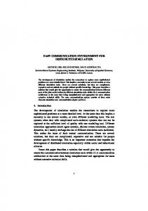
Utility Differences by Target Speed 40
Negotiate
35
Random
30
Utility
25 20 15 10 5 0 0
2
4
6
8
10
12
14
Target Speed
Fig. 1. The effect of increasing target speed on the utility obtained by two different sensor allocation schemes.
activities can have quantifiable effects on performance in domains where the passage of time matters. For example, in the distributed sensor network domain we describe later, a sensor allocation scheme requires a certain amount of time to decide on an allocation. The amount of time available depends in part on the speed at which the target is moving. Because this time is accounted for in Farm, the target of the sensing has the chance to move away from the sensor while the allocation is being generated, producing lower utility despite having an otherwise valid allocation. This effect can be seen in Figure 1. In that figure we compare the utility obtained by two allocation schemes as the target speeds are increased. The negotiate scheme requires time in which to compare allocations and communicate, while the random scheme simply picks sensors and ignores potential conflicts. Given enough time, the former produces a better result, while the latter gets a higher utility when time is scarce. A detailed discussion of these particular results is tangential here, we provide them as a motivating example of a situation where the temporal constraints of a situation are important, and can be captured by the environment provided by Farm. Communication actions are similarly modeled and monitored in such a way that message delivery times appropriate for the domain can be simulated. Farm has been used to model four different domains, including a variety of agents implementing different types of solutions for these domains. Scenarios consisting of 5000 autonomous agents have been run using 10 desktop-class Linux boxes. These environments will be discussed in more detail later in this paper. In the following section, we will provide a brief overview of the Farm simulator, followed by a discussion of how Farm relates to other MAS simulation environments. A more detailed look at Farm’s architecture is provided in section 3, along with a more in-depth examination of some of those features. We will conclude with examples of the environments that Farm has been used to create, and how Farm’s capabilities were used in their design.
Analyses • State / trend analysis
Driver • Non-agent activity
Farm Core
Meta-Agent
Meta-Agent
• Thread scheduling • Communication • State access / cache Agent Agent Agent
• Thread scheduling • Communication • State access / cache Agent Agent Agent
…
GUIs
• Plug-in management • State maintenance • Control flow
…
• State visualization
…
Meta-Agent • Thread scheduling • Communication • State access / cache Agent Agent Agent
…
Fig. 2. An example of Farm’s component architecture.
2 Overview As mentioned earlier, Farm is a distributed, component-based simulation environment. By distributed, we mean that discrete parts of the environment may reside on physically separate computing systems. In general, no assumptions are made about the type of system a part is run on, with respect to its operating system, memory or disk architecture. In particular, all that is required is a Java interpreter, and a means for that part to communicate with other parts of the environment (e.g. some sort of network connection). Each part, or component, in this simulation environment is responsible for some aspect of the simulation. Figure 2 shows how a typical set of components in the simulation are related. The hub of activity is the Farm core, which serves as a connection point for components, and also drives the control flow in the system as a whole. The connected components then fall into two categories: those which directly manage the agents running in the system, and those which exist to support those agents or the scenario as a whole. These agent managers are called meta-agents, as each acts as an interface to and for a cluster of one or more agents. This organization is solely for efficiency purposes, it has no effect on the outcome of the simulation, and the individual agents do not know what meta-agent they are controlled by. Agents are implemented are threads, although this is only for performance purposes - from an agent’s perspective they are completely segregated, and are not aware of or share memory with other agents which happen to also be resident at the same meta-agent. At runtime, agents are provided time in which to run, and other components (such as the drivers, analyses, and GUIs from figure 2) are given the opportunity to perform, analyze, or modify the simulation at well-determined times. The run cycle is partitioned such that tasks such as state maintenance or analysis may be performed without adversely affecting the simulation results, even if they require indeterminate time. This is covered in more detail in section 3.1. Such tasks are facilitated by the ability to store and retrieve global state information, which allows any given component to interact
160
Farm
140
Optimal
Time (min)
120 100 80 60 40 20 0 1
1.5
2
2.5
3
3.5
4
4.5
5
5.5
Metagents
Fig. 3. The effect of increasing the number of meta-agents on simulation duration.
with a snapshot of the system’s current state. The design of this data storage is covered in section 3.2.
3 Architecture As mentioned earlier, a simulation environment built using Farm is comprised of a number of components. Central to this arrangement is the Farm core, which handles component, control and state management. The meta-agents, specialized components which manage clusters of actual agents, implement much of the architectural-level functionality supporting those agents. More generally, component plugins provide the remainder of the system’s non-agent capabilities, typically including both domain-independent and domain-specific elements which create, manage and analyze the environmental state. An arbitrary set of components may be used for a given simulation scenario. For example, one might choose to reduce simulation overhead by running without visualization, or with it to get a clearer picture of the system’s state. Multiple, different analysis components could be used to capture different aspects of the system. Different environmental drivers could be used, depending on what type of scenario is desired. Some additional discussion of the plugin types we have used can be found in section 4. Whereas the types of the selected plugins are important in providing the capabilities and character of the simulation, it is just the total number of meta-agents which we are concerned about. The meta-agents are usually identical in functionality, and the size of the meta-agent set dictates how the load incurred by the agent population is distributed. Intuitively, in an environment with 100 agents, 5 meta-agents managing 20 agents each will run faster than a single meta-agent with all 100 agents. Experimental results looking at the effects of increasing the number of meta-agents can be seen in Figure 3, which shows its effect on total simulation time. The experimental setup consisted of a scenario containing 100 agents over a period of 60 seconds, using between one and five meta-agents. Recall that our goal is to provide each agent with an equal share of time, independent of what tasks the agents are actually performing. Ignoring the fact that an
individual agent will in reality map to a single meta-agent, an optimal system’s duration would then exactly distribute the total runtime across all available meta-agents:
���
�� ��� �� � � � � ���� �� ���� ��� �� �� ��� ���
...or 100 minutes with a single meta-agent. This duration would decrease at a rate inversely proportional to the number of additional meta-agents until they reach a 1:1 ratio with the agent population. Farm closely models the behavior of an optimal system, with differences between the two largely attributable to Farm’s environmental modeling and component communication. The number of meta-agents can be increased arbitrarily, although it generally does not make sense to allocate more than one per processor. Closely related to the total number of meta-agents is the load placed on each of them. Up to this point, we have assumed that agents allocated some duration of time will always require and use all that time. In practice, especially when agents can interact and may rely on one another for data, agents may have a considerable amount of idle time where they are awaiting a notification of one form or another. Farm allows agents to signal that they have no further actions to perform, so that they may preemptively release the time they have been allocated. In this way, they can reduce the actual runtime required, without changing the conceptual amount of time they have consumed in the simulation. If this capability is used, then the uniformity of agent load we have assumed so far may be incorrect, since some agents will be consuming different amounts of real processing time despite the fact that they all have identical simulated processing time. If there are different classes of agents, which may exhibit these different runtime characteristics, then this distribution should also be reflected in the allocation to avoid the need to estimate their actual computational requirements a priori. For example, if we have 5 meta-agents, 80 agents of type � and 20 of type � , a good allocation would place � and � on each meta-agent because the load assigned to each meta-agent would be most evenly balanced This scenario assumes no additional knowledge about the agents. If more details are available a more efficient allocation could be found, by reducing inter-meta-agent communication, for example. This will only affect the runtime characteristics of the simulation, and not affect the behavior of the agents themselves. The environmental driver is responsible for this allocation; it is provided with the number of meta-agents, which it uses with it’s internal characterization of the desired scenario to decide upon an allocation of agents.
��
�
3.1 Control Flow As the system starts up, the core acts as a registry for components, which contact the core as they are invoked. Components start by performing an initialization sequence, after which they wait for direction from the core. Control in the simulation is concerned with the passage of time. Our ultimate goal in this is to ensure that each agent in the system is provided the same amount of physical CPU time, to evaluate how those agents would perform in a continuous-time environment. In a perfect simulation, all agents would be able to operate asynchronously in parallel. However, competition for the local processor by agents resident at the same
meta-agent precludes this option if we wish to ensure fairness among them, and having one processor per agent is clearly infeasible for large numbers of agents. Thus, we approximate this behavior by sequentially assigning individual agents a slice of time in which to run. In between such opportunities an agent thread is paused, so the currently running agent has exclusive access to the CPU, as much as this is possible in a multitasking system. The simulation thus approximates how the agent population as a whole would act under real-time conditions, by breaking the timeline into a series of slices and providing each agent the appropriate amount of time to run for each slice. This process is separated into two different components of the simulator: the core and meta-agents. The core starts a pulse by notifying all meta-agents in parallel that their agents may run for some duration of time. Each meta-agent then sequentially wakes their local agents, and indicates the specified amount of time which they have available to them. We refer to this process as the agents receiving a pulse of time in which to run. Ideally, the meta-agent would externally recognize when this time had expired, and halt the agent’s thread preemptively. However, this technique can lead to deadlocks and other undesirable, nondeterministic behaviors that affect the real-time performance of other agents in the simulation, especially if the agent is interacting with a remote third party at the time of the preemption. To address this, agents are provided with a simple time-checking function which should be called periodically, that internally tracks how much time has been utilized. When their allotment has elapsed, this function blocks and notifies the meta-agent of completion. At the beginning the next pulse, the thread is restarted from this same location, so only a minor intrusion into the agent’s code is required. Just before and after this pulse is sent to the meta-agents, all components in the simulation are allowed an indeterminate amount of time in which to run. For example, before the agents are pulsed, a driver might update environmental data (e.g. a moving target’s position). After a pulse, analysis tools might take time to update statistics or visualizations. Because the agents are halted during this time, and the duration of these activities will not affect the results of the simulation, the designer is free to perform any number of activities during this period (at the expense, of course, of possibly increasing how long the simulation takes to run). The process of providing time before, during, and after each pulse is repeated by the simulation core until the simulation is completed. Because of this style of control flow, interactions do not take place between agents within a single time pulse - the effects of one agent will not be observable by another until that pulse has ended. This can lead to a certain amount of data, communication or behavioral incoherence in the system, the duration of which is bounded by the length of the time slice. For example, messages cannot be delivered faster than the pulse duration. In another situation, the effect of one agent’s action will not be observable by another immediately, but must wait until the following pulse when the result of that action can be shared. Mechanisms for addressing this issue are covered in more detail in section 3.5. The pseudo real-time nature of this control implies a certain amount of non-determinism to otherwise identical scenarios, as external events may effect the actual amount of processing time an agent receives during a window of real time. If determinism is required, Farm also supports a fixed notion of pulse time, which tracks the agent’s execution
progress, rather than just elapsed time. For example, instead of allocating 100ms per pulse, agents could be allocated a single pass through their main event loop. Thus, for each pulse, each agent’s pulse method would be called once, and (assuming the agents themselves are deterministic) the scenario as a whole will be deterministic because the same sequence of activities will be performed for each run. This allows repeatability, but prevents one from drawing strong conclusions about how the agents behave in real time. 3.2 Data Flow The Farm provides the components in the simulation with a data storage facility with characteristics similar to distributed shared memory. This is not inter-agent shared memory (agents are still assumed to interact via messaging), but instead provides an indirect means of interaction between the simulation components and a way to deliver environmental information to the agents. Using this scheme, components may store and retrieve data (properties) from a functionally common repository, enabling the data produced by one part of the simulation to be used by another. For example, an environmental driver might be responsible for updating the Target1:Location property. Agents needing to know that target’s location can then simply access this property. Similarly, each agent could store some notion of it’s current state in, for instance, the property Agent1:State. An analysis component could then find all properties *:State to capture a snapshot of all the agents in the system. Distributed data storage is accomplished in Farm through the use of a token system. Each globally-accessible property is associated with a token, which may be resident in the simulator core or at any one of the plugins. The owner of the token for a particular property is responsible for its storage; all reads and writes to that value are performed by or through it. The Farm core itself is responsible for keeping track of who owns the token for each property, somewhat like a specialized directory service. When a property is to be read for the first time by an entity, it optimistically assumes that it is stored at the core, and makes a request to the simulator for it. If it is being stored there, the property’s data will be delivered and the process continued uninterrupted. If a different plugin is the owner of that property, the core instead provides the requester with the name of that plugin. This can be used to contact the appropriate plugin and retrieve the data. This property-plugin mapping is then cached so future requests can be made directly to the owner plugin. Because plugins may leave, have their tokens removed, or otherwise lose control of a property, such future requests may fail. In this case the requester will again revert to the default assumption that the core itself is storing the property, since the core will either return the data or redirect the reader as needed. Property writes occur in a similar manner. If the writing entity has a cached propertyplugin mapping, then it will contact the appropriate plugin with the new data to be written. If no such mapping exists, or if the property is controlled by the core, then the simulator itself is contacted. As with reading, the simulator may store the data itself, or redirect the writer to the appropriate owner plugin. Because property owners may change over time, writers will again fall back to the default assumption that the property may be controlled by the core if the local knowledge is out of date. We will assume from here on that the plugins fulfill all of the storage responsibilities; simulation
core storage is generally only used as a fail-safe mechanism in case a plugin fails or is otherwise unavailable. An additional mechanism also exists which allows plugins to be automatically updated with a property’s data when it is updated. A list of recipients is attached to the owner’s token, so when the property is changed the new value can be automatically pushed to each member of the list. This pushed data is flagged as being cached, so the recipient knows it can safely read from the data, but writes must still be propagated back to the owner. The owner is responsible for ensuring that this remotely cached data is kept up to date. This token-based scheme is really just a support structure; the more interesting problem is determining which plugin should be assigned to manage a particular property, and what other plugins should be included in that property’s recipient list. The difference between the duration of local and remote writes and reads can be as much as two orders of magnitude 1, caused by the messaging duration and the time needed to encode and decode the information. As the number of data accesses grows, this overhead has the potential to add a noticeable amount of time to the duration of the simulation. Because the time needed to perform remote accesses can be a significant overhead cost in this framework our objective is to minimize the number of messages needed to support each property, under the assumption that this will similarly minimize the overall time cost associated with that property. The total size of the data being transferred is typically uniformly small enough that it can be ignored. We have explored several different strategies to address this cost. If we view a particular allocation as being constant for the duration of a simulation, this cost � � can be estimated with the following function for a particular plugin � accessing property �:
��
�
� �� ��
� ��
� �� � � ��
(1)
otherwise
� is the set of available plugins, � � is the designated owner of the property, and � � is the list of recipients to which the property will be automatically pushed. � �� and ��� are the number of reads and writes of � by �, respectively. The total cost for property �, including strategy overhead, is then: ��
�
¾�
��
��
�
¾�
�� �
��� � � � � �����
(2)
In addition to the remote access and push costs, � � also includes the overhead needed to set up and (eventually) tear down the owner relationship, in addition to the overhead needed to initiate pushing. This equation assumes an owner is assigned and that �� and �� do not change. If � � is allowed to change over time, the last term will then be Æ ��� � , where Æ is the number of times ownership is assigned. If Æ � and the assignment is allowed to vary, then equation 2 is only an approximation; a more
� � �
1
�
Testing the average duration of 100,000 sequential, unloaded accesses showed that on average, local reads/writes of a 10 character string took 0.0005/0.0044ms each, respectively. Remote reads/writes took 0.7986/0.8081ms each.
precise computation of � � must take into account the costs incurred under each assignment episode, rather than an overall aggregate. Note that in this revised formulation Æ may also be zero, indicating no remote owner is assigned and the simulation core is the de facto owner. Strategies. Our objective is to find an optimal policy for choosing � � and �� so that we can minimize �� . Because there are varied access patterns to particular pieces of data, and can be near-continuous access to a single property by different plugins (for example, an agent’s state being maintained by one and analyzed by another), it is not clear that a single strategy will be best for all properties. In the extreme, if there is no pattern to the accesses then an equally random assignment of ownership will be as good as any other on average. Fortunately, since particular plugins have specified roles and associated property needs there should be a definite pattern to the accesses. We will evaluate several strategies to see which is appropriate for the types of simulations and plugins we currently use. Our baseline strategy (C) employs a simple but inefficient centralized assignment. All properties are stored at the simulator core, so all accesses will be made remotely. In �� �� . We will then evaluate the last writer (LW) strategy, this case, �� � �� where the plugin which makes the last write access will be assigned ownership of the property. In this case, the owner will change over time. Two analogous techniques are evaluated where the first reader (FR) or writer (FW) is assigned ownership, which does not change over the remainder of the simulation. In other tests, the last writer, first reader and first writer strategies will be augmented with an aggressive push mechanism (LWP, FRP, FWP), where all remote reads will result in the reading plugin being added to the automatic push list for that property. A first-access, pushed strategy was also evaluated, but dropped from these experiments because it was in all cases nearly identical to FWP, since the vast majority of properties are written before a read is attempted. Another strategy will add a so-called ”adjustable” push to the first reader and writer strategies (FRAP, FWAP) using an exponential, recency-weighted usage estimation as a form of online learning. This is done in constant space for each property using the formula:
�
���·½
�� � ���� ·½ � �� � �
�
�
(3)
��� represents the overhead-inducing activity associated with property � by plugin � at time �. This value, reset to zero at the beginning of each time step, is incremented by 1 each time � is read, and decremented by � each time it is pushed to �. A nonnegative � indicates that � is being read locally at least as much as it is being pushed to the agent (a desirable condition). � is the step-size parameter ( � � � �), which controls how much the historical values affect the estimate. In these experiments � � . Then, ���·½ is the estimated amount of activity at time � � �, with which � can determine if it should change its membership status on �’s push list. If that estimate shows that a push mechanism would reduce or exceed remote accesses and overhead, then a push is requested or rejected respectively. In practice, a change is made only when � ���·½ � � to avoid thrashing. This strategy is similar to the PoP (push-or-pull) strategy described in [2], although we use a somewhat simpler switching heuristic.
Comparison of Different Token Assignment Strategies
Comparison of Different Token Assignment Strategies 350
Overhead
80
Remote Get
70
Remote Set
340
60
Time (sec)
Messages (1000s)
90
50 40 30
330 320 310
20 300
10 0
290
C
LW
FR
FW
LWP
FRP
FWP
S
FRAP FWAP SAP
C
LW
FR
FW
LWP
FRP
Type
Type
(a)
(b)
FWP
S
FRAP FWAP SAP
Fig. 4. Comparison of message activity and time between different property ownership strategies in the DSN domain.
We will look at a technique which post-processes the access pattern (S), in an attempt to learn what the most appropriate static assignment should be. In this case, the owner and push lists are calculated as follows to minimize the total number of remote accesses per property:
�� �� � ���� �
� �¾�
��� �
�� � � ����� � ����
���
(4) (5)
Equation 4 specifies push targets as those which have a greater number reads than the total number of writes, which equals the number of pushes they would receive. Equation 5 selects the plugin which has the greatest cost, taking into account the benefits of pushing which have just been calculated. After selecting � � , it is removed from � � if necessary. Because this information is known a priori, we can avoid the overhead needed to set up individual push requests. This information is instead bundled along with the ownership message, resulting in fewer messages and a time cost, at the expense of making a single message somewhat larger. We will also examine the effects of using this learned policy to prime the initial state of the adjustable technique described earlier (SAP). Results. The strategies were evaluated using a distributed sensor allocation simulation, consisting of nine plugins with varying access patterns. Each strategy was tested in 50 different random scenarios, and the total cost in terms of remote accesses and overhead messages determined. Roughly 100 properties, accessed a total of 75,000 times, were managed by the system. Remote accesses include any reads or writes to non-local data, while overhead is the collection of messages needed to support the various schemes, such as ownership notification, push requests and pushed data. The results are shown in Figure 4. The most obvious conclusion that can be drawn from these results is the reduction in message activity permitted by the push-based technique. All six strategies which employed it produced nearly half the messages of the best technique which did not, and
Comparison of Different Token Assignment Strategies
Comparison of Different Token Assignment Strategies
Overhead
280
Remote Get
260
Remote Set
240
80
Time (sec)
Messages (1000s)
100
60 40
220 200 180 160 140
20
120
0
100
C
LW
FR
FW
LWP
FRP
FWP
S
FRAP FWAP SAP
C
LW
FR
FW
LWP
FRP
Type
Type
(a)
(b)
FWP
S
FRAP FWAP SAP
Fig. 5. Comparison of message activity and time between different property ownership strategies in the graph coloring domain.
close to four times fewer messages than the simple centralized solution. This was caused by the fact that there were some components, such as the analysis and graphing plugins, which read from properties on every time pulse which were changed less frequently. For example, if a particular property were updated only every other pulse, then the push technique cuts the number of messages in half compared to one which remotely read the value on every pulse. Also apparent from Figure 4b was the fact that lowering the total level of messaging does not strictly correspond to a reduction in time, even where computational overheads are similar at first glance. The differences lie in the manner remote accesses have been apportioned over the timeline. For example, the learned technique (S), although it has at most an equal number of total messages and minimal runtime computational requirements, takes longer to complete than its counterparts which more aggressively pushed data (e.g. LWP, FRP, FWP). In some cases, an additional measure of parallelism is created, when a group of plugins set or push data to a plugin which would otherwise need to retrieve that data serially. Other differences are observed because of the cumulative effects of minor duration variances between strategies. In these tests, the allocations generated by the S and FRP strategies produced a set of variables which were owned by one of two plugins. One was a reader, the other a writer, so one of the two would be forced to make a remote access for each property at each time pulse. In this particular instance, it was observed that remote sets were approximately 1 ms slower than remote gets for the same data. These small delays accumulated to produce a significant portion of the overall duration differences between these two strategies. A Student’s t-test was performed across all pairs of strategies. This showed that the FRP and FRAP strategies took significantly less time than other strategies in this ), while they were indistinguishable from each other. In fact, none domain (� � � of the adjustable strategies FRAP, FWAP, SAP took significantly less time (� � � ) than their static counterparts. This is a result of the relatively fixed access patterns that take place for each property. We have also tested these strategies in two other domains with different load patterns. The first is a graph coloring scenario consisting of 12 plugins and 80 agents, which attempt to solve a similarly sized 3-coloring graph using a distributed constraint
�
�
Comparison of Different Token Assignment Strategies 1400
Remote Get
1200
Messages (1000s)
Comparison of Different Token Assignment Strategies 1050
Overhead
950
Remote Set
Time (sec)
1000 800 600 400
850 750 650 550
200 0
450
C
LW
FR
FW
LWP
FRP
FWP
S
FRAP FWAP SAP
C
LW
FR
FW
LWP
FRP
Type
Type
(a)
(b)
FWP
S
FRAP FWAP SAP
Fig. 6. Comparison of message activity and time between different property ownership strategies in the learning domain. Domain LW DSN � � GC ��� � L �� �
FR �� �� � � �
FW � � ��� � �
LWP FRP FWP S �� �� �� �� �� � � � �� � � � �� � �� � �� �
FRAP FWAP SAP �� �� �� �� �� � � � � � �� � ��
Fig. 7. Percentage reduction in simulation duration versus centralized, observed under each strategy in the distributed sensor network, graph coloring and learning domains.
satisfaction algorithm. This managed approximately 350 properties accessed 100,000 times over 100 pulses. We again see the FRP strategy doing well here, as does the S strategy. In this case, the access patterns were such that the post-process analysis produced an assignment which naturally exploited parallelism, by having the analysis component own many of the properties it required. This meant the agent plugins frequently had to remotely set their data, but the bulk gets performed by the analysis component were local, resulting in a net savings in time. The learned (S) strategy which produces ), followed by FRP which also assigned ownthis allocation does best here (� � � ership of these properties to the analysis component. The second is a learning domain consisting of 14 plugins and 500 agents, which are each learning an appropriate policy for a simple, individually random -armed bandit problem. This managed 1000 properties, accessed over 1 million times over 1000 pulses, but with a simpler usage pattern. Specifically, the use of mobile analysis code allows the bulk of these properties (97%) to be used by just a single plugin. From Figure 6, one can see how dramatically property relocation can reduce the amount of messaging needed to support it, with corresponding decreases in total running time. The peculiar fact that no components read from those properties leads to little differentiation from strategies that push data, and poor performance of techniques where ownership is based on reading. In the latter case the absence of readers means the properties stay resident in the simulation core, so those accesses are all remote. In this case, the previously good FRP strategy is no better than centralizing the data. The quantitative reductions in time observed under each strategy are shown in Figure 7. Based on these tests, the learned (S) strategy, seems to offer the most consistent
�
performance in our typical scenarios, with time reductions of around 5%, 29% and 44% across the three domains when compared to the default centralized strategy. However, it does not it does uniformly produce the best results, it requires the user to generate data needed to perform the analysis, and it will not adapt well to cases where the correct allocations vary widely from one episode to the next. The first reader push (FRP) strategy offers similar or better performance in two out of the three domains with a 7% and 22% reduction in time in DSN and graph coloring respectively, and one might argue that the conditions in the learning domain are atypical. In our opinion, this strategy is the suitable choice for most domains, although there is clearly a need for an alternative under some conditions. The first writer push (FWP) exhibits lower performance in two of the domains, and also suffers from an worst case analogous to that seen in FRP (an absence of writers). This also holds for the writer (LWP) strategy, with the additional caveat that thrashing may occur in domains where two separate writers coexist. Although not seen in these tests, we suspect that in domains where the usage pattern for properties change over time that the adjustable reader strategy (FRAP) may prove best, because it can adapt to changing conditions. However, this is not the case in our existing domains, and the additional overhead usually causes a slight reduction in performance. Both this and the learned technique would benefit from a richer representation of the potential benefits of parallelism and more accurate message delivery costs, which could address some of the deficiencies noted above.
Other Strategies. There are other techniques that have been developed for content distribution networks and large scale storage systems which in theory are applicable to this environment, but in practice we suspect that the cost-benefit ratio would not be favorable. For instance, hierarchical distribution frameworks [16] are an effective way of disseminating information. The facilities needed to support such a technique would not be difficult to implement in the existing framework as an extension of the push mechanism. However, we feel that given the typically small number of plugins which need to access a particular property that the reduction in load provided by such a hierarchy would be minimal. Multicast notification would be a useful way to reduce the cost of pushed information if it were supported by the underlying network, but relying on this limits where Farm can be used. A potential solution to this is applicationlayer multicast [1], but because the underlying protocols are usually still unicast and the distribution target pool is small, the benefits would seemingly be minimal. Consistency relaxation [17], another mechanism which can be used to reduce traffic, is touched on in section 3.5. As alluded to above, Farm also uses Java’s RMI and serialization services to support mobile code, for cases where data retrieval bottlenecks are otherwise unavoidable. With this technique, instead of remotely retrieving and locally processing a potentially large amount of data, a specialized function is delivered to and run by directly by property owners. This function can be written to use only local data, with the intention of returning a more concise view to the originator. This is particularly useful for analysis components, which frequently need to access data that scales in number with the agent population. For example, the analysis component used in the learning domain computes averages of two properties set by each agent. Because the analysis and meta-
TCP From Meta-Agents
TCP To Meta-Agents
Meta-Agent • Communication is performed outside of simulation core • Agents send and receive messages through meta-agents • Meta-agent then routes messages to destination Incoming Messages
Outgoing Messages
Agent
Incoming Messages
Outgoing Messages
Agent
Incoming Messages
Outgoing Messages
Agent
Fig. 8. Farm communication flow.
agent components are distinct, when running with a population of 500 agents, this will immediately result in 1000 remote property gets or sets regardless of the strategy being employed. We use mobile functions to avoid this by first computing local averages at each plugin, and then transferring only these values. The dominating costs of this technique scale with the number of plugins, resulting in substantial savings in bandwidth and time. 3.3 Communication To improve scalability, communication takes place entirely outside of the core. Instead, communication occurs between meta-agents, and individual agents send and receive messages via their managing meta-agent, as shown in Figure 8. When a new metaagent registers with the core, all existing meta-agents are told about the addition, and the new meta-agent is given a list of all other members - thus a fully-connected graph of meta-agents is maintained. When an agent sends a message, it is added to a per-agent outgoing queue. The meta-agent selects ready messages from these queues and checks its address table to determine the recipient’s owning meta-agent. If the meta-agent is found, the message is delivered. If it is not found, it uses the list of known meta-agents to find the appropriate one, and that mapping is then recorded in the address table. Thus each meta-agent will learn a mapping for only necessary destination agents. As messages are received by a meta-agent, they are added to a per-agent incoming message queue, which is polled by the agent as necessary. We wish to have a relatively realistic network model, so care is taken when sending messages. A potential race condition also exists for message delivery, as one agent’s message may reach another agent before it has technically been sent in the global time line. As messages are added to an agent’s outgoing queue, they are marked with a delivery time. The delivery time of a message will be that of the prior message in the queue, plus a bounded random transit duration which can be weighted by the length of the message. A message loss rate probability may also be set. At the end of a pulse, each meta-agent searches the outgoing message queues of its local agents, and sends messages if permitted by the assigned delivery times. These messages are queued for delivery at the destination meta-agent. At the beginning of the next pulse, those received
80 70
Time (min)
60 50 40 30 20 10 0 100
300
500
700
900
1100
Agents
Fig. 9. The effect of increasing the number of agents on simulation duration.
messages are delivered to the appropriate incoming queue for each agent. The agent is then responsible for monitoring its queue and handling new messages. We are investigating other potential communication paradigms, such as a defined routing network or a distance-limited broadcast scheme, to provide additional communications scenarios for agents to explore. While this decentralized communication mechanism scales very well, it prevents other components from directly observing or analyzing message traffic. Gross statistics, such as total incoming and outgoing messages, are currently computed and stored as global properties by individual meta-agents. Other statistics can be computed in a similar manner to compensate for this design decision. The exact messaging protocol is left intentionally unspecified and abstract. Agents simply send Message objects, which can be extended as needed. The destination agent then receives Message objects in its incoming queue. Parsing of the object is performed automatically. 3.4 Scalability Some discussion of the scalability of Farm has been mentioned earlier. The component architecture of Farm, and specifically its ability to segregate the agent population into groups under the control of distributed meta-agents, leads the environment to large scale scenarios. Because the agents effectively run in parallel because of this distribution, the primary constraint is having available computing power to run such simulations in a reasonable amount of time. Figure 9 shows a sample of Farm’s scalability characteristics, from the results of a series of repeated trials with a scenario length of 60 seconds. The number of metaagents was fixed at five, and the number of agents gradually increased from 100 to 1000, with a 1:4 ratio of targets to sensors. The distributed resource allocation domain from section 4.1 was used, because the movement of targets provides a need for continual re-evaluation and activity. The agents in this domain do actual problem solving, and
use communication to negotiate over areas of contention. The initial results seen in this graph are promising. In comparing the 100 agent point from Figure 9 with the 5 meta-agent point in 3, one might also note a significant difference in simulation duration. For example, the 100 agent case here took only 6 minutes, as compared to 124 minutes previously. Both experiments used the same machines, domain and agent population, but the trials from Figure 9 allowed the agents to signal their meta-agent if they have no additional work to do, using the technique mentioned earlier in section 3. This allows the agent’s pulse cycle to be ended prematurely, with potentially large savings in actual running time without loss of precision in the simulation results. In our scenario, if there are more agents in an environment of constant size, there is a higher probability that additional computation will be needed to resolve the correspondingly larger number of conflicts. This is seen in non-linearity of the data in Figure 9, where disproportionately more time is used in larger populations. In this way, the system avoids expending effort simulating agents’ “idle” time, which gives Farm some of the benefit that a strictly event-based simulation environment would posses. Perhaps more interesting than “how large can it get?” is the question “what prevents it from getting large?”. No design is perfect, and parts of Farm’s architecture can inhibit scale in order to permit other features. Typically, the most constraining feature is the remote access of data, as outlined in section 3.2. This is necessary to facilitate state analysis, but excessive usage can accumulate a large time penalty. In general, such scenarios will just take longer to process than if the data storage were completely distributed. If an appropriate allocation strategy is used, then in many cases data caching and mobile code can ensure agents are not unduly penalized for the time required to update remote data. Another constraint, related to data flow, is environmental maintenance. The task of creating and maintaining the simulation environment (e.g. placing sensors, moving targets, etc.) is typically the responsibility of a single component. Like any other, this component may be distributed for load balancing purposes, but it is still a single process limited to the resources present at its local processor. Like the agents, it also accesses state data, but since it has the responsibility of maintaining the entire state, the potential burden is much more concentrated. Extremely large, complex or dynamic environments might therefore benefit from separating the environmental maintenance into separate components, much as the agents themselves are separated. Thus, one might have a target component, a sensor component, and the like, each with a specific, tractable responsibility. 3.5 Coherency Whenever an environment is distributed, the problem of coherency arises because entities on one processor may have data inconsistent with that on another. One must try to make sure that interactions between processors are as faithfully represented as those occurring on the same processor. The data consistency problem in Farm manifests itself in the time between when one agent changes a value to when that change can be observed by another. In between those events, the system can lose some measure of coherence. Because Farm is
attempting to replicate the behavior of a centralized simulation, data storage should exhibit strong coherence, and components always use the most up-to-date property when possible. One could envision a system where a weaker form of coherence might be acceptable to some components (e.g. visualization) in order to reduce overheads. In this case, techniques used to minimize the cost associated with maintaining such a heterogeneous population could be employed, as shown in [17]. However, due to the relatively small population of plugins in a typical scenario, the costs associated with maintaining such special cases may outweigh the potential benefits. We have previously outlined Farm’s data dissemination technique in section 3.2. In the absence of cached information, coherence is maintained by the single owner for each property, which handles all read and write accesses for the property. These accesses are serialized by the owner, ensuring that consistency is maintained. In the case where data has been pushed to and cached by remote components, the owner is also responsible for immediately updating those components with the new information. Owner coherence is maintained by locking the property for the duration of the update, while remote coherence is limited by the network and processing delay incurred by the update. Communication coherency is also important. Farm must ensure that a message is delivered when appropriate, and from the recipient’s perspective, not before it was actually sent. As outlined in section 3.3, this is accomplished in a manner similar to the data flow. Messages from the agents are queued for delivery during the pulse, and only sent after the pulse has completed. The receiving meta-agent queues incoming messages, which are delivered to their final recipient when the specified delivery time has been reached. A more insidious form of inconsistency occurs when the meta-agents are distributed across a heterogeneous set of machines. Because the agent’s computational effort is measured in seconds, one group of agents may effectively be allocated more time simply because the processor they happen to reside on can perform more computations in the same amount of time. A few strategies can be employed to compensate for this problem. One could compute a processor-to-real time ratio for all machines in the pool, and use that to scale the actual time allocated by individual meta-agents. In Farm, this is accomplished by first determining a baseline performance standard, either by prespecifying it or by having the simulation core to dynamically compute one from the computer it resides on. This baseline value is then provided to the meta-agents, who dynamically determine their individual performance metrics by computing a common benchmark. We use the Linpack benchmark [3] to produce these performance measures. The ratio of the baseline value to a meta-agent’s individual performance metric is used to weight the execution time it allocates to the agents under its control. Another strategy to address the issue of heterogeneity is to statistically remove the problem through repeated trials where the agent population is shuffled between hosts. A third option (clearly requiring less effort) is to simply ensure your server pool is sufficiently homogeneous, or accept the performance differences as a byproduct of working in a realistic environment. For the results presented in this paper, the experiments were performed using a group of similarly configured workstations.
Fig. 10. The distributed sensor network domain implemented in Farm.
4 Environments Several computational environments have been implemented using Farm, each taking about two days to implement the environment itself, and the agents taking from a day to a week depending on their complexity and the availability of source code. Each environment generally consists of a driver, which instantiates and maintains the environment, and analysis components, which generates statistics at runtime, and a set of one or more types of agents. In addition, several generic components have been developed which may be used across all environments. These include a graphing component, property log, and time driver. 4.1 Distributed Resource Allocation The distributed resource allocation environment is an abstraction of the distributed sensor network (DSN) problem [10]. A complete solution would reason about a range of issues, from role assignment to low level task scheduling to multi-target data association. The underlying problem, however, is much more straightforward. The environment consists of a number of sensors and mobile targets, and the high level objective is to use the sensors to track them. Each sensor has limitations on its range and usage. This then reduces to a resource allocation problem, where the attention of the sensors must be allocated so that all the targets are tracked.
Several plugins were created for this domain. The first was a driver, which is responsible for assigning sensor and target agents to meta-agents, and for creating and maintaining the sensor environment. This includes determining locations for the simulated sensor nodes, updating target locations as they move, and maintaining sensortarget observability lists. These lists were stored as properties, so that they can easily be accessed by the individual agents. This and other data was also used by an analysis plugin, which determined the possible and current utility produced over time, tracked message totals, and sensor allocation conflicts, among other things. Much of the data it uses are produced by individual agents, which are then stored as global properties. One can see that as the system scales, this data transfer can become significant, which motivates the property storage discussion presented earlier in section 3.2. Farm’s generic graphing plugin, seen at the bottom of Figure 10, was used to visualize some of this data. The analysis component works by aggregating the data and producing some sort of summary statistic at each time pulse. This statistic is also stored as a property, the name of which can be provided to the graphing plugin at launch time so it can find and graph the values over time. Another domain-specific visualization component, shown at the top of Figure 10, displays the current sensor field, along with target allocations, conflicts and negotiation patterns. This works in a manner similar to the analysis component, aggregating data produced by individual agents with location data from the driver to produce its image. The same data collection costs mentioned above also motivate the need for a component-based system such as Farm employs that allows one to run both with and without potentially expensive components like these visualizers. Our comprehensive solution to this problem is implemented as a homogeneous collection of sophisticated JAF agents, which run in real time in both the Radsim simulator and hardware. In the Farm environment there are two types of simpler agents: sensor agents, each of which controls a single sensor, and tracking agents, each of which is responsible for tracking a single target. The driver provides the track managers with a list of candidate sensors, i.e. those which are in range of its target, and the track manager must determine which sensors it wants to use. The track managers must then coordinate to resolve conflicts so all targets are tracked. The SPAM negotiation protocol [12] was implemented to solve this problem. This domain was the incentive behind Farm’s creation, and has shown itself to be particularly useful in debugging and evaluating SPAM. Because Farm scales to much greater numbers, and also eliminates most of the complicating, but ultimately tangential factors (relative to resource allocation), development and evaluation of the protocol was much easier in this environment than in the original detailed simulator. We were also able to directly use almost all the code from the original JAF-based implementation, so improvements made in the Farm environment were easily mapped back the more realistic Radsim and hardware environments. 4.2 Graph Coloring The well-known graph coloring domain was implemented as a means of both testing the generality of SPAM in a new domain, and also to compare its performance against reference protocols known to work on graph coloring. The driver in this domain was simpler than for DSN, as it only needs to create the nodes and edges of the graph. A
Fig. 11. The graph coloring domain implemented in Farm.
domain visualizer was also written, which was used to produce the image in Figure 11. We use the layout procedure described in [20] to produce satisfiable graphs of arbitrary size using a defined number of colors. Currently the resulting graph is static, although we intend to add an additional dynamic component to it in the future. A separate analysis component evaluates the possible and actual number of coloring constraints, which is then visualized using the graphing component. Three agents have been implemented in this domain, using protocols derived from descriptions in [20]. The results of these tests can be found in [11]. 4.3 SAT The boolean satisfiability problem, or n-SAT, is another well-studied domain. Our driver for this environment constructs random SAT problems with a specified number of variables, clauses and clause length. It can also read and instantiate CNF formula encoded in the DIMACS format, allowing researchers to make use of the large collections of SAT benchmark materials available online. Individual agents correspond to the variables from the formula, which must then interact and exchange information in some way to find a satisfying solution if one exists. As with other domains, an analysis component was written which can monitor the progress of the search over time. 4.4 Learning Evaluation The learning domain we developed is different than the others, in that was not intended to produce an environment where a number of agents can work together addressing a
Fig. 12. The learning domain implemented in Farm. This shows the average results of two learning techniques being run concurrently, each with a learning population of 500 agents.
common environment. Instead, a number of individual agents learn in parallel on separate problems. Specifically, we have implemented a simple -armed bandit problem [18], along with several agent types instantiating different reinforcement learning techniques. The purpose of this was to create an environment where a number of tests can be run concurrently, to provide more immediate, comparative feedback as visualized by Farm’s graphing plugin in Figure 12. In this figure we compare how the percentage of agents performing the optimal action changes over time between two different techniques, where each measurement for each technique is the average over the behavior of 500 concurrently running agents. The driver for this domain was responsible for determining what types of learning agents to create. As with the DSN domain, this is a potentially heterogeneous collection agents, so allocation was performed by distributing a smaller, representative sample of this collection to each meta-agent. As mentioned earlier in section 3.2, the learning domain also employed a more complex analysis component, which used mobile code to first generate aggregate statistics at each component, and only transfer a summary back to the analysis component. These individual summary statistics were then combined to produce the global statistic. This resulted in a dramatic savings in time and message traffic, at the expense of a more complex implementation. This particular domain is also differentiated by its use of the deterministic notion of pulse time. Agent behavior is controlled so that instead of running for a certain number of milliseconds, they are allowed only a fixed number of passes (1) through their control loop per pulse. This allows us to ignore the computational costs of the learning techniques (which might vary by implementation), and instead focus on their theoretical convergence rates. This control style may be turned off to obtain real time performance as well.
5 Related Work Attempts have been made [13, 8] to define the set of features and characteristics that a multi-agent simulator should posses. The topics described in these efforts are important, in that they can help guide designers towards a comprehensive, robust solution.
Farm, however, is not intended to provide a complete simulation solution - instead it tries to provide a relatively simple environment where agents possess only the most germane functionality. Much of the complexity of a real environment can be either abstracted away, or approximated through the use of black-box style components which provide agents with necessary information, when the actual process of obtaining that information is unimportant. Thus, much of the underlying modeling structures which make other simulators unique is absent in Farm.
5.1 MACE3J MACE3J [6], like Farm, is primarily intended to simulate large numbers of largegrained agents. It includes mechanisms for different styles of event and messaging control, data collection, and a lightweight agent definition model. It is also scalable, but does so under a multiprocessor-based scheme, taking advantage of the capabilities inherent in lower level system software to manage many of the inter-processes and inter-thread issues which arise in simulation. While this method is undoubtedly more efficient than the distributed approach we have selected, it also requires additional physical overhead in the form of an actual multi-processor machine, or a cluster of machines tied together with appropriate software. In this sense, Farm is more closely related to the original MACE [5], which also employed a distributed architecture. Farm places more emphasis on the real-time aspects of agent behavior, as progress in a scenario is driven by the passage of time, not events or messages, and the effectiveness of an agent is affected by the duration of its computations. In contract, MACE3J’s event driven control with synchronization points allows for more deterministic results. In other ways the two environments are similar: Farm also supports repeatability, varied communication models, transitionable agent models and data collection and display tools. MACE3J’s support for randomized event sequences is a feature we intend to add to Farm in the future.
5.2 SPADES The SPADES (System for Parallel Agent Discrete Event Simulator) environment is similar to Farm in many respects [15]. Like Farm, SPADES has a distributed architecture where multiple agents may share one physical processor, and the actual execution time used by individual agents is tracked. Unlike Farm, SPADES uses an event-based scheme to monitor progress, which allows scenarios to be more easily repeatable than in Farm’s continuous-time approach. Although Farm does offer a deterministic mode, as outlined in Section 3.1, SPADES’ event-based approach can potentially offer a better tradeoff between simulation granularity and the overhead incurred maintaining synchronization across agents. The drawback of this design is the need for centralized control. Since the engine must maintain a global view of the actions taking place in the system, this component’s load will grow proportionally with the number of agents in the system. Conversely, we feel that Farm’s more modular architecture and distributed state mechanism avoids this bottleneck, while offering greater flexibility to the simulation designer.
5.3 Swarm Like Farm, the Swarm [14] simulation environment is a modular domain-independent framework. It offers the ability to probe agents’ state and beliefs, and graphically display them, similar to the logging and graphing tools provided with Farm. Fundamentally, the two differ in their representation of time passing. Swarm uses a discrete event system, where a point in time in not reached or seen until some event has been scheduled to take place then. Farm uses a real time approach where time passes regardless of what events are taking place. Both techniques are valid, but serve different purposes. In addition, Swarm agents have a different character to them, as they are generally modeled as a set of rules, or responses to stimuli. Conversely, Farm agents are built more like a conventional program, where the designer develops classes and routines to exhibit agent behavior. Again, both approaches have their merits depending on the problem to be addressed. 5.4 CoABS Grid The CoABS Grid (CG) [9] is a middleware system designed to integrate a collection of architecturally heterogeneous agents into a single consistent environment. It has many of the characteristics of a simulation environment, although it is more robust in that the environment and the effects of agent activities need not necessarily be simulated. CG has some features that directly provide domain services to the agents, such as capability registration and search, secure communications, and directory services, which in a Farm simulation would traditionally be considered part of the agent solution. However, in the spirit of avoiding unnecessary complexity that we have espoused, one could envision, for example, a Farm directory service plugin in much the same way drivers are used to relieve the agents of other burdens. Like Farm, CG strives to be a scalable solution, has support for optional visualization and logging tools, mobile code, and fully distributed point-to-point communication. Farm differs from CG in its tighter control of time, specifically in that agents are allocated a particular amount of time in which to run by the Farm core. Because CoABS agents may be legacy systems or non-native wrapped agents this level of timing control and accountability is difficult to achieve in that framework. 5.5 MASS Our earlier simulation environment, the Multi-Agent System Simulator [19], is quite different than Farm. It provides a richer, quantitative view of the world, where agent activities and their interactions are modeled using a hierarchical task decomposition language, consumable and non-consumable resources have constraints which can affect behavior, and an agent’s beliefs may differ from objective fact. As with the earlier example, agents are built using JAF, which itself has a fair amount of complexity. All of these features are desirable for evaluating sophisticated agents in context, but at the same time they can be distracting when only a subset of behaviors need analysis. In addition, the environmental models and communication mechanisms are centralized, and the agents, while distributed, run as separate processes, so the environment as a whole
does not scale well past 40 agents or so. The DECAF [7] agent framework also has a similar character and purpose to JAF/MASS, although it does not have a centralized simulation environment, and it offers built-in brokering and name services which JAF lacks. In most other respects, DECAF compares to Farm in much the same way as JAF. 5.6 Radsim Unlike most of the other environments mentioned here, Radsim is not a general simulation framework. Instead it is a real-time, domain-specific simulator designed to accurately model a collection of radar platforms as they attempt to track targets moving through space[10]. We mention it here because it represents an extreme case in the spectrum of simulators, where the actors in the system must recognize and handle virtually every aspect of a problem with a high level of realism. This complexity is critical for testing comprehensive solutions, particularly if the actual environment the solution will run in is otherwise physically or practically unavailable. However, this same complexity can prevent the environment from scaling, and hinder development of critical subsystems. We feel this argues for a heterogeneous approach, where targeted, scalable simulation results, such as Farm can provide, coupled with the type of detailed experiments that can be done in a complex environment such as Radsim, will in the end produce a higher quality solution. 5.7 VMT The Vehicle Monitoring Testbed (VMT) was one of the first distributed simulation environments designed to support distributed intelligent processing [4]. It is interesting to note that the same capabilities which we currently address in Farm, such as the desire to scale, overcoming resource bottlenecks, and facilitating distributed control, were the same motivating issues in a system designed 20 years ago. Although the VMT environment has a more specialized purpose, it still shares several features with Farm, including a similar messaging scheme, a notion of global time and a synchronization mechanism ensuring distributed processes receive equal amounts of time.
6 Summary Farm is a multi-agent simulation environment designed to handle large scale simulations and custom designed analysis, visualization and content while tracking agent activity in simulated real time. The main simulation entity acts as a hub, by accepting and managing connections from distributed plugins, providing execution prompts to those plugins, and maintaining a common, globally accessible data repository. Agents in the system are implemented as threads, but are autonomous in character, require communication to interact, and do not share memory. These agents are organized in groups on distributed processors, where their real-time CPU usage is monitored and rationed in accordance with the simulated environment’s design. By distributing both the agents and analysis tools in this fashion, Farm is able to exploit available computing power
to handle very large environments, while retaining the ability to effectively model real world performance. Issues relating to scale and coherency are closely tied to the distributed nature of the system. On one hand, poor data and computational distribution can lead to communication and processing bottlenecks. On the other, because agents are distributed across processors, care must be take to ensure temporal, data and communication consistency. Different strategies for managing these issues were covered. The environment so far has been used to create scenarios containing more than 5000 individual agents. Several domains have also been implemented, including a distributed sensor network, graph coloring and SAT. Further information on Farm can be found at: http://mas.cs.umass.edu/research/farm
References 1. S. Banerjee, B. Bhattacharjee, and C. Kommareddy. Scalable application layer multicast. In Proceedings of the 2002 conference on Applications, technologies, architectures, and protocols for computer communications, pages 205–217. ACM Press, 2002. 2. P. Deolasee, A. Katkar, A. Panchbudhe, K. Ramamritham, and P. J. Shenoy. Adaptive pushpull: disseminating dynamic web data. In World Wide Web, pages 265–274, 2001. 3. J. J. Dongarra, C. B. Moler, J. R. Bunch, and G. W. Stewart. LINPACK Users’ Guide. Society for Industrial and Applied Mathematics, Philadelphia, PA, USA, 1979. 4. E. Durfee, D. Corkill, and V. Lesser. Distributing a Distributed Problem Solving Network Simulator. In Proceedings of the Fifth Real-time Systems Symposium, pages 237–246, December 1984. 5. L. Gasser, C. Braganza, and N. Herman. MACE: a flexible testbed for distributed ai research. In Distributed Artificial Intelligence, M.N. Huhns, ed. Pitman/Morgan-Kaufmann, 1987. 6. L. Gasser and K. Kakugawa. MACE3J: fast flexible distributed simulation of large, largegrain multi-agent systems. In Proceedings of the first international joint conference on Autonomous agents and multiagent systems, pages 745–752. ACM Press, 2002. 7. J. R. Graham, K. S. Decker, and M. Mersic. DECAF - a flexible multi agent system architecture. Autonomous Agents and Multi-Agent Systems, 2003. 8. S. Hanks, M. E. Pollack, and P. R. Cohen. Benchmarks, test beds, controlled experimentation, and the design of agent architectures. AI Magazine, 14(4):17–42, Winter 1993. 9. M. L. Kahn and C. D. T. Cicalese. CoABS grid scalability experiments. In Proceedings of the Second International Workshop on Infrastructure for Scalable Multi-Agent Systems at Autonomous Agents, May 2001. 10. V. Lesser, C. Ortiz, and M. Tambe. Distributed Sensor Networks: A multiagent perspective. Kluwer Publishers, 2003. 11. R. Mailler and V. Lesser. A Mediation Based Protocol for Distributed Constraint Satisfaction. The Fourth International Workshop on Distributed Constraint Reasoning, pages 49–58, August 2003. 12. R. Mailler, R. Vincent, V. Lesser, J. Shen, and T. Middlekoop. Soft real-time, cooperative negotiation for distributed resource allocation. In Procceedings of the 2001 AAAI Fall Symposium on Negotiation, 2001. 13. M. G. Marietto, N. David, J. S. Sichman, and H. Coelho. Requirements analysis of multiagent-based simulation platforms: State of the art and new prospects, 2002. 14. N. Minar, R. Burkhart, C. Langton, and M. Askenazi. The swarm simulation system: A toolkit for building multi-agent simulations. Technical report, Sante Fe Institute, 1996.
15. P. Riley and G. Riley. SPADES — a distributed agent simulation environment with softwarein-the-loop execution. In S. Chick, P. J. S´anchez, D. Ferrin, and D. J. Morrice, editors, Proceedings of the 2003 Winter Simulation Conference, December 2003. 16. P. Rodriguez, C. Spanner, and E. W. Biersack. Web caching architectures: Hierarchical and distributed caching. In Proceedings of the 4th International Web Caching Workshop, 1999. 17. S. Shah, A. Bernard, V. Sharma, K. Ramamritham, and P. Shenoy. Maintaining temporal coherency of cooperating dynamic data repositories. Computer Science Technical Report TR01-52, University of Massachusetts at Amherst, November 2001. 18. R. S. Sutton and A. G. Barto. Reinforcement Learning: An Introduction. MIT Press, Cambridge, MA, 1998. A Bradford Book. 19. R. Vincent, B. Horling, and V. Lesser. An Agent Infrastructure to Build and Evaluate MultiAgent Systems: The Java Agent Framework and Multi-Agent System Simulator. Lecture Notes in Artificial Intelligence: Infrastructure for Agents, Multi-Agent Systems, and Scalable Multi-Agent Systems., 1887, January 2001. 20. M. Yokoo. Distributed Constraint Satisfaction. Springer Series on Agent Technology. Springer, 1998.