Keywordsâ computer networks, formal models, multilayer networks. ... Presentation Layer;. 7. ... based on OSI RM â layers 5 through 7 are collapsed into the.
International Journal of Computer Trends and Technology (IJCTT) – Volume 26 Number 1 – August 2015
A Multilayer Model of Computer Networks Andrey A. Shchurov Department of Telecommunications Engineering, Faculty of Electrical Engineering Czech Technical University in Prague, Czech Republic
Abstract— The fundamental concept of applying the system methodology to network analysis declares that network architecture should take into account services and applications which this network provides and supports. This work introduces a formal model of computer networks on the basis of the hierarchical multilayer networks. In turn, individual layers are represented as multiplex networks. The concept of layered networks provides conditions of top-down consistency of the model. Next, we determined the necessary set of layers for network architecture representation with regard to applying the system methodology to network analysis. Keywords— computer networks, formal models, multilayer networks. I. INTRODUCTION Applying a system methodology to network analysis [1] is a relatively new approach, particularly in the Internet Protocol (IP) world. The fundamental concept is that network architecture should take into account services and applications which this network provides and supports. It is important to note that this concept is completely supported by the most recent practical approaches such as Business-Driven Design [2] and Application Centric Design [3]. On the other hand, one of the major goals of modern physics is providing proper and suitable representations of systems with many interdependent components, which, in turn, might interact through many different channels. As a result, interdisciplinary efforts of the last fifteen years have leaded to the birth of complex networks theory [4] which uses graphs as powerful mathematical tools for modelling pairwise relationships among sets of objects/entities. Traditionally graphs capture only a single form of relationships between objects [5]. However, complex networks rely on different forms of such relationships, which can be naturally represented by multilayer networks [6]. Assuming that all layers are informative, they can provide complementary information. Thus, we can expect that a proper combination of the information contained in the different graph layers leads to a formal network representation (a formal model) which will be appropriate for applying the system methodology to network analysis. The rest of this paper is structured as follows. Section 2 introduces the related work. Section 3 presents the formal model of computer networks based on the concept of multilayer networks. In turn, Section 4 focuses on the set of
ISSN: 2231-2803
layers for network architecture representation. Finally, conclusion remarks are given in Section 5. II. RELATED WORK The multilayer approach for the modelling of computer networks can be roughly classified into two categories: • multilayer networks (network architecture representation); • reference models (layers definition). A. Multilayer networks Recent surveys in the domain of multilayer networks provided by Kivela et al. [7] and Boccaletti et al. [8] give a comprehensive overview of the existing technical literature and summarize the properties of various multilayer structures. However, it is important to note that the terminology referring to systems with multiple different relations has not yet reached a consensus – different papers from various areas represent similar terminologies to refer to different models, or distinct names for the same model. B. Reference models The ISO/OSI Reference Model (OSI RM) [9] was developed years ago for application developers, equipment manufacturers and network protocol vendors as an open standard for constructing network devices and applications/services that can work together. The model partitions computing systems into seven abstraction layers: 1. Physical Layer; 2. Data Link Layer; 3. Network Layer; 4. Transport Layer; 5. Session Layer; 6. Presentation Layer; 7. Application Layer. However, this conceptual model has never been implemented in practice. Instead of it, increasing popularity of TCP/IP based networking has led developers to use the TCP/IP Protocol Suit [10] [11] [12] which five layers are based on OSI RM – layers 5 through 7 are collapsed into the Application Layer. In turn, IETF standards RFC 1122 [13] and RFC 1123 [14] define the TCP/IP Reference Model. This model is compatible with OSI RM and TCP/IP Protocol Suit but it partitions computing systems into four abstraction layers – layer 1 (Physical Layer) is removed from the model.
http://www.ijcttjournal.org
Page 12
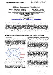
International Journal of Computer Trends and Technology (IJCTT) – Volume 26 Number 1 – August 2015 III.MULTILAYER MODEL A type of multilayer network of particular relevance for computer networks is a hierarchical multilayer network [7], in which the bottom layer constitutes a physical network and the remaining layers are virtual layers that operate on top of the physical layer. On the other hand, the concept of layered networks [15] provides the condition of top-down consistency based on the facts: • for each node on a given layer there is a corresponding node (or nodes) on the layer below; • for each logical path between two nodes on a given layer there is a path (or paths) between the corresponding nodes on the layer below. Thus, the formal basic definitions of multilayer networks [8] (adapted to the hierarchical top-down approach) can be used as a starting point. In this case: Fig. 1 Multilayer model of computer networks.
Definition 1: Let the graph 𝑀𝑀 = (𝑉𝑉, 𝐸𝐸) denote the computer network as a hierarchical multilayer network: 𝑀𝑀 = (𝑉𝑉, 𝐸𝐸)
where 𝑀𝑀 is a multi-layered 3D graph (see Fig. 1); 𝑉𝑉(𝑀𝑀) is a finite, non-empty set of components (hardware or software); and 𝐸𝐸(𝑀𝑀) is a finite, non-empty set of component-tocomponent interconnections (information links). In turn: 𝑁𝑁
and
𝑁𝑁
𝑉𝑉 = � 𝑉𝑉𝛼𝛼 𝛼𝛼=1
𝑁𝑁
𝐸𝐸 = �� 𝐸𝐸𝛼𝛼 � � �� 𝐸𝐸𝛼𝛼,(𝛼𝛼−1) � 𝛼𝛼=1
𝛼𝛼=2
where 𝑉𝑉𝛼𝛼 is a finite, non-empty set of components on layer 𝛼𝛼; 𝐸𝐸𝛼𝛼 is a finite, non-empty set of intralayer component-tocomponent interconnection on layer 𝛼𝛼 ; 𝐸𝐸𝛼𝛼,(𝛼𝛼−1) is a finite, non-empty set of interlayer relations (projections) between components of a given layer 𝛼𝛼 and the layer below (𝛼𝛼 − 1); and 𝑁𝑁 is the number of layers.
On the other hand, two main elements of multilayer networks are [7]: • intra-layer graphs; • inter-layer graphs. In this case:
Definition 2: Let the subgraph 𝐺𝐺𝛼𝛼 denote a layer of the computer network: 𝐺𝐺𝛼𝛼 = (𝑉𝑉𝛼𝛼 , 𝐸𝐸𝛼𝛼 )
Definition 3: Let the subgraph 𝐺𝐺𝛼𝛼(𝛼𝛼−1) denote a cross-layer of the computer network: 𝐺𝐺𝛼𝛼(𝛼𝛼−1) = (𝑉𝑉𝛼𝛼 , 𝑉𝑉(𝛼𝛼−1) , 𝐸𝐸𝛼𝛼,(𝛼𝛼−1) )
where 𝐺𝐺𝛼𝛼,(𝛼𝛼−1) is an interlayer bipartite subgraph of 𝑀𝑀; 𝑉𝑉𝛼𝛼 is a finite, non-empty set of components on layer 𝛼𝛼, 𝑉𝑉(𝛼𝛼−1) is a finite, non-empty set of components on layer (𝛼𝛼 − 1) ; 𝐸𝐸𝛼𝛼,(𝛼𝛼−1) ⊆ 𝑉𝑉𝛼𝛼 × 𝑉𝑉(𝛼𝛼−1) is a finite, non-empty set of interlayer relations (projections) between components of a given layer 𝛼𝛼 and the layer below (𝛼𝛼 − 1). As mentioned above, the concept of layered networks [15] strictly relies on the fact that a node in a given layer depends on a corresponding node in the layer below, i.e. each individual component viα ∈ Vα has at least one corresponding (α−1) (α−1) neighbour vj ∈ V(α−1) where vj must satisfy the (α−1)
� ∈ Eα,(α−1) , i.e. |Vα | ≤ |Eα,(α−1) |. condition �viα , vj It is important to note that the degree (or valency) of vertices of Gα,(α−1) represents the technological solutions which were used to build the system [16]: • d(viα ) > 1; viα ∈ Vα – clustering technology representation; (α−1) (α−1) • d�vj � > 1; vj ∈ V(α−1) – virtualization and replication technologies representation; (α−1) • d(viα ) = d�vj � = 1 – a special case of dedicated components. Based on Definitions 2 and 3, computer networks can be represented as:
where 𝐺𝐺𝛼𝛼 is an intralayer subgraph of 𝑀𝑀; 𝑉𝑉𝛼𝛼 is a finite, nonempty set of components on layer 𝛼𝛼; and 𝐸𝐸𝛼𝛼 ⊆ 𝑉𝑉𝛼𝛼 × 𝑉𝑉𝛼𝛼 is a finite, non-empty set of intralayer component-to-component interconnections on layer 𝛼𝛼.
ISSN: 2231-2803
http://www.ijcttjournal.org
𝑁𝑁
𝑁𝑁
𝛼𝛼=1
𝛼𝛼=2
𝑀𝑀 = �� 𝐺𝐺𝛼𝛼 � � �� 𝐺𝐺𝛼𝛼,(𝛼𝛼−1) �
Page 13
International Journal of Computer Trends and Technology (IJCTT) – Volume 26 Number 1 – August 2015 From the perspective of system methodology, intralayer subgraphs 𝐺𝐺𝛼𝛼 are the main source of initial data for the network analysis processes; and interlayer subgraphs 𝐺𝐺𝛼𝛼,(𝛼𝛼−1) make these processes consistent on all layers of the formal model. In practice, intralayer subgraphs 𝐺𝐺𝛼𝛼 are not monolithic structures: a set of protocols is predefined for each (physical or virtual) layer. For example, a wireless access point (AP) must support at least two different protocols: (1) one for wired and (2) one for wireless communications. Moreover, these protocols can support different topologies. As a consequence, each intralayer subgraph 𝐺𝐺𝛼𝛼 consists of a fixed set of components connected by different types of information links. A type of multilayer network of particular relevance for this case are multiplex [6] [17] or multidimensional [18] networks, in which different layers represent different types of component-to-component interconnections. Hence, we should rewrite Definition 2 as follow: Definition 2*: Let the subgraph 𝐺𝐺𝛼𝛼 = (𝑉𝑉𝛼𝛼 , 𝐸𝐸𝛼𝛼 , 𝑆𝑆𝛼𝛼 , 𝑃𝑃𝛼𝛼 ) denote a layer of the computer network, where 𝐺𝐺𝛼𝛼 is a labeled intralayer subgraph of 𝑀𝑀 ; 𝑉𝑉𝛼𝛼 is a finite, non-empty set of components on layer 𝛼𝛼 ; 𝐸𝐸𝛼𝛼 is a finite, non-empty set of intralayer component-to-component interconnections on layer 𝛼𝛼 ; 𝑆𝑆𝛼𝛼 is a vertices label set; and 𝑃𝑃𝛼𝛼 is a set of predefined protocols for layer 𝛼𝛼. In this case:
Fig. 2 Intralayer subgraph representation as a multiplex network.
𝑆𝑆𝛼𝛼 = � 𝑆𝑆𝑖𝑖𝛼𝛼 𝑣𝑣𝑖𝑖𝛼𝛼 ∈𝑉𝑉𝛼𝛼
IV. LAYERS DEFINITION As mentioned above, the ISO/OSI Reference Model has is a finite non-empty totally ordered set of where never been implemented in practice. Thus, the TCP/IP component specifications (at least the set of supported Protocol Suit can be used as a starting point. On the other 𝛼𝛼 communication protocols) or the label of the vertex 𝑣𝑣𝑖𝑖 of 𝐺𝐺𝛼𝛼 . hand, network architecture representation should be as clean In turn, 𝐺𝐺𝛼𝛼 is represented as a multiplex network (see Fig. 2): and simple to understand as it can be. As a consequence (in contrast to the developer community) the business community |𝑃𝑃𝛼𝛼 | (end-users) faces the following challenges [16]: 𝐺𝐺𝛼𝛼 = � 𝐺𝐺𝛽𝛽𝛼𝛼 • Physical Layer and Data Link Layer cannot be divided 𝛽𝛽=1 in the case of commercial off-the-shelf (COTS) network equipment; where 𝐺𝐺𝛽𝛽𝛼𝛼 = �𝑉𝑉𝛼𝛼 , 𝐸𝐸𝛽𝛽𝛼𝛼 � is a sub-subgraph which is defined by • Transport Layer and Application Layer cannot be the communication protocol 𝑝𝑝𝛽𝛽𝛼𝛼 ∈ 𝑃𝑃𝛼𝛼 ; and 𝐸𝐸𝛽𝛽𝛼𝛼 ⊆ 𝐸𝐸𝛼𝛼 is a finite, divided in the case of COTS software. Moreover, end-users do not need services and applications non-empty set of intralayer component-to-component interconnections on sub-layer 𝛽𝛽 of layer 𝛼𝛼 . An edge themselves – they need tools to solve their business problems. �𝑣𝑣𝑖𝑖𝛼𝛼 , 𝑣𝑣𝑗𝑗𝛼𝛼 � ∈ 𝐸𝐸𝛼𝛼 belongs to 𝐺𝐺𝛽𝛽𝛼𝛼 iff both components 𝑣𝑣𝑖𝑖𝛼𝛼 and 𝑣𝑣𝑗𝑗𝛼𝛼 However, neither OSI RM not TCP/IP Protocol Suit provides support this protocol, i.e. 𝑝𝑝𝛽𝛽𝛼𝛼 ∈ 𝑆𝑆𝑖𝑖𝛼𝛼 and 𝑝𝑝𝛽𝛽𝛼𝛼 ∈ 𝑆𝑆𝑗𝑗𝛼𝛼 (each pair of a layer to represent the enlarged viewpoint of end-users (business goals). As a consequence, a common joke is that components 𝑣𝑣𝑖𝑖𝛼𝛼 and 𝑣𝑣𝑗𝑗𝛼𝛼 can be connected by at most |𝑃𝑃𝛼𝛼 | OSI RM should have three additional layers [19]: possible edges). 8. User Layer; 9. Financial Layer; Based on Definitions 2* and 3, computer networks can be 10. Political Layer. finally represented as: In practice computer network focus on solving problems at |𝑃𝑃𝛼𝛼 | layer 10 (but they are usually limited by layer 9). 𝑁𝑁 𝑁𝑁 Hence, we should define the additional layer which can 𝛼𝛼 𝑀𝑀 = �� �� 𝐺𝐺𝛽𝛽 �� � �� 𝐺𝐺𝛼𝛼,(𝛼𝛼−1) � represent the enlarged system functionality or business goals. 𝑆𝑆𝑖𝑖𝛼𝛼
𝛼𝛼=1
𝛽𝛽=1
ISSN: 2231-2803
𝛼𝛼=2
http://www.ijcttjournal.org
Page 14
International Journal of Computer Trends and Technology (IJCTT) – Volume 26 Number 1 – August 2015
Fig. 3 Basic multilayer reference model.
As a consequence, this layer is based on functional models [1] (end-user requirements representation). The basic multilayer reference model is shown in Fig. 3. From the viewpoint of the hierarchical multilayer network, the physical layer constitutes a physical network and the logical, service and functional layers are virtual layers that operate on top of the physical layer. Unfortunately, the basic model does not take into account the environment impact. The problem can be solved by two additional layers [20] (see Fig. 4): • The engineering environment layer. This layer defines external engineering systems (power supply systems, climate control systems, physical security systems, etc.) that are vital for normal operation of computer networks. It is based on topological models [1], where engineering systems and computer networks are represented as individual components. • The social environment layer (or layer 8 of OSI RM [19]). This layer defines organization infrastructures or human networks. It represents persons or groups of persons and their working relationships based on electronic communications. It is important to note that all these additional layers lie beyond the ISO/OSI RM and the TCP/IP Protocol Suit but they provide a necessary complement to it with regard to applying the system methodology to network analysis. V. CONCLUSIONS The fundamental concept of applying the system methodology to network analysis is that network architecture should take into account services and applications which this network provides and supports.
ISSN: 2231-2803
Fig. 4 Extended multilayer reference model.
In this work we determined a formal model of computer networks on the basis of the hierarchical multilayer networks in which the bottom layer constitutes a physical network and the remaining layers are virtual layers that operate on top of the physical layer. In turn, the representation of individual layers is based on the concept of multiplex networks in which different sub-layers represent different types of component-tocomponent interconnections for a fixed set of components (hardware or software). On the other hand, the concept of layered networks provides the condition of top-down consistency of the model. Next, we determined the necessary set of layers for network architecture representation with regard to applying the system methodology to network analysis. This set covers: • hardware-based aspects (components and their interconnections) of computer networks; • software-based aspects; • network environments (external engineering systems and organization infrastructures); • network business goals based on end-user requirements Using this model and the graph theoretical metrics, both static and dynamic system analysis can be performed: • The static analysis determined the characteristics of each layer based on the layer structure (or topology) [21] [22]. • The dynamic analysis (or fault injection simulation) provides a means for understanding how distributed systems behave in the presence of faults [23] [24].
http://www.ijcttjournal.org
Page 15
International Journal of Computer Trends and Technology (IJCTT) – Volume 26 Number 1 – August 2015 In turn, the approaches of automated transformation of network specifications and end-user requirements into abstract formal models are beyond the scope of this paper. This problem requires a separate analysis – in the case of complex or non-standard computer networks, it may not be a routine exercise in practice. ACKNOWLEDGMENT This article has originated within the framework of research and development activities at the Department of Telecommunication Engineering (Czech Technical University in Prague, Faculty of Electrical Engineering). REFERENCES [1] J. D. McCabe, Network Analysis, Architecture, and Design, 3rd ed., Morgan Kaufmann Publishers, 2007. [2] R. White and D. Donohue, The Art of Network Architecture: BusinessDriven Design, 1st ed., Cisco Press, 2014.
[10] A. S. Tanenbaum and D. J. Wetherall, Computer Networks, 5th ed., Prentice Hall Press, 2011. [11] J. F. Kurose and K. W. Ross, Computer Networking: A Top-Down Approach, 6th ed., Pearson, 2012. [12] D. E. Comer, Internetworking With TCP/IP Volume I: Principles, Protocol, And Architecture, 6th ed., Pearson, 2015. [13] IETF RFC 1122 Requirements for Internet Hosts - Communication Layers, 1989. [14] IETF RFC 1123 Requirements for Internet Hosts - Application and Support, 1989. [15] M. Kurant and P. Thiran, "Layered Complex Networks," Phys. Rev. Lett., vol. 96, no. 13, April 2006. [16] A. A. Shchurov, "A Formal Model of Distributed Systems For Test Generation Missions," International Journal of Computer Trends and Technology, vol. 15, no. 6, pp. 128-133, 2014. [17] L. Sola, M. Romance, R. Criado, J. Flores, A. García del Amo and S. Boccaletti, "Eigenvector centrality of nodes in multiplex networks," Chaos, vol. 23, no. 2, p. 033131, 2013.
[3] S. Hummel, Cisco Design Fundamentals: Multilayered Design Approach For Network Engineers, 1st ed., Cisco Press, 2015.
[18] M. Berlingerio, M. Coscia, F. Giannotti, A. Monreale and D. Pedreschi, "Foundations of Multidimensional Network Analysis," in Advances in Social Networks Analysis and Mining (ASONAM), 2011 International Conference on, 2011.
[4] M. Newman, "The Structure and Function of Complex Networks," SIAM Review, vol. 45, no. 2, pp. 167-256, 2003.
[19] T. A. Limoncelli, C. J. Hogan and S. R. Chalup, The Practice of System and Network Administration, 2nd ed., Addison Wesley, 2007.
[5] M. v. Steen, Graph Theory and Complex Networks: An Introduction, 1st ed., Maarten van Steen, 2010.
[20] V. A. Khlevnoy and A. A. Shchurov, "A Formal Approach to Distributed System Security Test Generation," International Journal of Computer Trends and Technology, vol. 16, no. 3, pp. 121-127, 2014.
[6] M. De Domenico, A. Sole-Ribalta, E. Cozzo, M. Kivela, Y. Moreno, M. Porter, S. Gomez and A. Arenas, "Mathematical Formulation of Multilayer Networks," Phys. Rev. X, vol. 3, no. 4, p. 041022, December 2013.
[21] A. A. Shchurov and R. Marik, "A Formal Approach to Distributed System Tests Design," International Journal of Computer and Information Technology, vol. 3, no. 4, pp. 696-705, July 2014.
[7] M. Kivela, A. Arenas, M. Barthelemy, J. Gleeson, Y. Moreno and M. Porter, "Multilayer networks," Journal of Complex Networks, vol. 2, no. 3, pp. 203-271, 2014.
[22] A. A. Shchurov and R. Marik, "Dependability Tests Selection Based on the Concept of Layered Networks," International Journal of Scientific & Engineering Research, vol. 6, no. 1, pp. 1165-1174, January 2015.
[8] S. Boccaletti, G. Bianconi, R. Criado, C. del Genio, J. Gomez-Gardenes, M. Romance, I. Sendina-Nadal, Z. Wang and M. Zanin, "The structure and dynamics of multilayer networks," Physics Reports, vol. 544, no. 1, pp. 1-122, 2014.
[23] M. Kurant, P. Thiran and P. Hagmann, "Error and Attack Tolerance of Layered Complex Networks," Phys. Rev. E, vol. 76, no. 2, August 2007.
[9] ISO/IEC Std 7498:1994 Information technology - Open Systems Interconnection - Basic Reference Model, 1994.
ISSN: 2231-2803
[24] S. Buldyrev, R. Parshani, G. Paul, E. Stanley and S. Havlin, "Catastrophic cascade of failures in interdependent networks," Nature, vol. 464, pp. 1025-1028, 2010.
http://www.ijcttjournal.org
Page 16