Dr.K.Sri Rama Krishna et al. / International Journal of Computer Science & Engineering Technology (IJCSET)
A Neural Network Inverse Modeling Approach for the Design of Spiral Inductor Dr.K.Sri Rama Krishna1 J.Lakshmi Narayana2 Dr.L.Pratap Reddy3 1
Professor & Head of ECE, V.R Siddhartha Engineering College, Vijayawada, A.P Email:
[email protected]
2
Professor & Head of ECE, Andhra Loyola Institute of Engineering and Technology Vijayawada, A.P E-mail:
[email protected] 3
Professor & Head of ECE, Jawaharlal Nehru Technological University, Hyderabad, A.P. E-mail:
[email protected]
Abstract— Artificial Neural networks (ANN’s) have now a days become efficient alternatives to conventional methods such as numerical modeling methods which could be computationally expensive, or analytical methods which could be difficult to obtain for new devices, or empirical models whose range and accuracy could be limited. ANN’s have also been used for solving a wide variety of RF and Microwave Computer Aided Design (CAD) problems. Analysis and design of a spiral inductor has been presented in this paper using ANN forward and inverse models. For the analysis a simple ANN forward model is used where the inputs are geometrical parameters and the outputs are electrical parameters and for the design, an Inverse model is used where the inputs are electrical parameters and the outputs are geometrical parameters. Direct Inverse model can be obtained by swapping the input and output data used to train the forward model. Training of neural network using inverse model may become difficult due to the non uniqueness of the input and output relationship in the model. A neural network inverse modeling approach is used to solve such a problem is by detecting multi valued solutions in the training data. The data containing multivalued solutions are divided into groups according to derivative information using a neural network forward model such that individual groups do not have the problem of multivalued solutions. Multiple inverse and forward models are built based on the divided data and are then combined to form a complete model. This Paper also presents a comparison of Direct inverse model and the indirect Inverse model. Keywords— Spiral Inductor, ANNs, Training Algorithms, forward and inverse models.
I. INTRODUCTION Nowadays, as the demand for wireless communication continues to expand, the need for high quality (Q) inductors for high-level integration of RF circuit, in order to reduce cost, has become more important. Of late, many research activities have been focused on the design, model and optimization of spiral inductors on silicon substrate. However, most of the reported Q of spiral inductors is limited to below 10 at giga hertz range [1]. Previously, inductors were not considered as standard components such as transistors, resistors or capacitors where models are included in the standard technology library. However, the demands for inductor models are increasing, as RF circuits on Si with acceptable performance are now feasible. Models that can predict the behavior of inductor over a broad range of frequency are important for circuit simulation and layout optimization. Thus has arisen the need to develop a generic procedure to produce good inductor models for RFIC applications [2]. Artificial Neural Networks (ANNs) are information processing systems with their design inspired by the studies of the ability of the human brain to learn from observations and to generalize by abstraction [3, 4]. The fact that neural networks can be trained to learn any arbitrary nonlinear input–output relationships from corresponding data has resulted in their use in a number of areas such as pattern recognition, speech processing, control, biomedical engineering etc. ANNs can also be applied to RF and microwave Computer-Aided Design (CAD) problems as well. A neural network model for microwave device/circuit can be developed from measured/simulated microwave data, through a process called training after ANN architecture is set up. Once the ANN model is fully developed, the computation time is usually negligible and much faster than any single full-wave EM simulator. Though a considerable effort is required in developing an ANN model, it is worthy doing so if repeated design analysis and optimization is required. Neural Network techniques have been used for modeling wide variety of microwave applications such as embedded passives [5], transmission-line components [6]–[8], vias [9], bends [10], coplanar waveguide (CPW) components [11], spiral inductors [12], FETs [13, 14], amplifiers [15], [16], etc. An increased number of RF/microwave engineers and researchers have started taking serious interest in this emerging technology. This paper presents the design and analysis of circular spiral inductor at a frequency of 10GHz with Alumina (εr=3.9) as the material and also proposes an Artificial Neural Network model to determine the Quality factor of
ISSN : 2229-3345
Vol. 2 No. 3
54
Dr.K.Sri Rama Krishna et al. / International Journal of Computer Science & Engineering Technology (IJCSET)
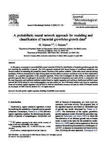
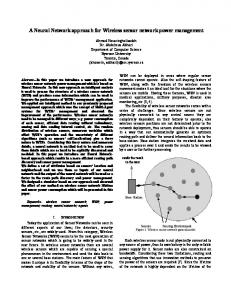
the spiral inductor for various diameters. Performance of the proposed model is evaluated in terms of average and maximum estimated errors using different Neural Network Training Algorithms. Comparison of the results of the proposed model with that of EM simulated results has also been presented. The remainder of the paper is organized as follows: Section 2 focuses on Design of Spiral Inductor and Section 3 discusses the ANN model for the analysis of spiral inductor. Section 4 explains the design of spiral inductor using direct inverse model. Finally, section 5 summarizes the presented research work. II. DESIGN OF SPIRAL INDUCTOR The Geometry of Circular Spiral Inductor is shown in Figure1
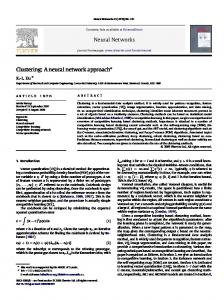
Figure 1. Spiral Inductor Geometry The design specifications are as follows: W – width of Trace =10m S- space between Trace =2m N- Number of Turns=1.5 f-Frequency=10GHz Din-Inner Diameter=50m -250m =Material Conductivity=5.6*107 t= Metal Thickness=1m r =Dielectric constant=3.9 T-Oxide Thickness=7m The outer diameter is given by (1) Dout = Din+N*2(W+S) The trace Length is given by (2) l= 4*Dout*N-4*(N-1)*(W+S) The value of Inductance is given by L= (9.375* 0*N2*Davg2) / (11*Dout – 7*Davg) (3) Where Davg = (Dout+Din)/2 III. ANN MODEL FOR THE ANALYSIS OF SPIRAL INDUCTOR (FORWARD MODEL) ANN represents a promising modeling technique, especially for data sets having non-linear relationships that are frequently encountered in engineering [17-23]. In the course of developing an ANN model, the architecture of ANN and the learning algorithm are the two most important factors [24]. ANNs have many structures and architectures [25].The class of ANN and/or architecture selected for a particular model implementation depends on the problem to be solved. In this paper, the multilayered perceptron (MLP) neural network architecture is used in calculating the Quality Factor of Sprial Inductor. MLPs have a simple layer structure in which successive layers of neurons are fully interconnected, with connection weights controlling the strength of the connections. The MLP comprises an input layer, an output layer, and a number of hidden layers one can be trained using many different learning algorithms. A simple and accurate neural model is proposed for calculating the quality Factor of a Spiral Inductor as shown in figure 2. ANN models are a kind of black box models, whose accuracy depends on the data presented to it during training. A good collection of the training data, i.e., data which is well-distributed, sufficient, and accurately
ISSN : 2229-3345
Vol. 2 No. 3
55
Dr.K.Sri Rama Krishna et al. / International Journal of Computer Science & Engineering Technology (IJCSET)
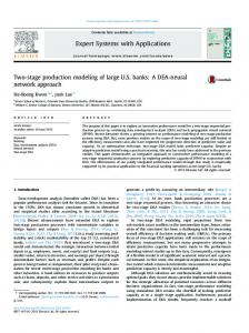
simulated, is the basic requirement to obtain an accurate model. For microwave applications, there are two types of data generators, namely measurement and simulation. The data sets used in this paper were obtained from the simulation and contain 1350 samples. The training data sets used here are software simulated and contain 950 samples and are trained with a learning rate of 0.1 for 1000 epochs. The aim of the training process is to minimize the training error between the target output and the actual output of the ANN. Selection of training parameters and the entire training process mostly depend on experience besides the type of problem at hand. After several trials, it was found in this paper that three layered network achieved the task in high accuracy. The most suitable network configuration found was 1: 5 : 1 for the analysis of Spiral Inductor. The model is trained with nine learning algorithms namely, Back Propagation (BP), Sparse Training (ST) , Conjugate Gradient (CG), Adaptive Back Propagation (ABP), Quasi-Newton MLP (QN-MLP), Quasi-Newton(QN), Huber-Quasi-Newton (HQN), Auto Pilot (MLP3) and Simplex Method (SM) [24,25]. For validation, the neural models results have been compared with the EM simulated results. The training and test results obtained from the forward neural models are given in Table 1 from which it is clear that the results of the neural models trained by the Quasi Newton and Simplex method algorithms are better than those of the neural models trained by other algorithms for the forward model .In order to validate the neural model for the analysis of Spiral Inductor, comprehensive comparisons have been made. In these comparisons, the results obtained from the neural model trained by Quasi Newton algorithm for the forward model were compared with EM Simulated results and presented graphically(Fig: 3).
Figure 2. Neural model for Calculating Quality factor of a Spiral Inductor (Forward Model)
Figure 3. Comparison of Diameter Vs Qualtity factor obtained using the simulated results, with that of the neural model (forward) of a spiral Inductor.
ISSN : 2229-3345
Vol. 2 No. 3
56
Dr.K.Sri Rama Krishna et al. / International Journal of Computer Science & Engineering Technology (IJCSET)
Table 1: Training and test results for Quality factor of a Spiral Inductor of Neural Forward model.
Learning Algorithms BP (MLP3) ST CG ABP QN (MLP) QN HQN Auto Pilot (MLP3) SM
Training Error 7.83564*10-4 4.88842*10-3 7.76555*10-4 7.77857*10-4 3.292135*10-5 3.30162*10-5 3.29849*10-5 3.298313*10-5 3.29169*10-5
Testing Learning Algorithms
Avg. Error
BP (MLP3)
0.07786
Worst Case Error
Correlation Coefficient
0.4338
0.99999994
ST
0.07786
0.4338
0.99999994
CG
0.07736
0.4141
0.99999994
ABP
0.07755
0.4134
0.99999994
QN (MLP)
0.00323
0.0172
0.99999999
QN
0.00324
0.0171
0.99999999
HQN
0.00324
0.0171
0.99999999
Auto Pilot
0.00324
0.0171
0.99999999
SM
0.00325
0.0169
0.99999999
IV. ANN MODEL FOR THE DESIGN OF SPIRAL INDUCTOR (DIRECT INVERSE) The neural model shown in figure 4 computes the Diameter for a given Quality factor and this model is known as Direct Inverse model where the inputs are electrical parameters and the outputs are geometrical parameters. Direct Inverse model can be obtained by swapping the input and output data used in the forward model. The most suitable network configuration found was 1: 5 : 1 for the Design of Spiral Inductor. The neural model for the design of spiral inductor using direct inverse model is trained with nine learning algorithms namely, Back Propagation (BP), Sparse Training (ST) , Conjugate Gradient (CG), Adaptive Back Propagation (ABP), Quasi-Newton MLP (QN-MLP), Quasi-Newton(QN), Huber-Quasi-Newton (HQN), Auto Pilot (MLP3) and Simplex Method (SM) [24-27]. For validation, the neural models results have been compared with the EM simulated results. The training and test results obtained from the neural model are given in Table 2 from which it is clear that the results of the neural model trained by the Huber Quasi Newton and Autopilot algorithms are found to be better for the direct Inverse model. In order to validate the neural model for the design of Spiral Inductor, comprehensive comparisons have been made. In these comparisons, the results obtained from the neural models trained by HQN for direct reverse model are compared with EM simulated results and presented graphically(Fig:5).
ISSN : 2229-3345
Vol. 2 No. 3
57
Dr.K.Sri Rama Krishna et al. / International Journal of Computer Science & Engineering Technology (IJCSET)
Figure 4. Neural model for Calculating Diameter of a Spiral Inductor (Direct Inverse Model)
Table 2: Training and test results for Diameter of a Spiral Inductor of Neural Direct Inverse Model
Learning Algorithms BP (MLP3) ST CG ABP QN (MLP) QN HQN Auto Pilot (MLP3) SM
Learning Algorithms
ISSN : 2229-3345
Training Error 0.1914855 0.198594 0.191939 0.192044 0.1919584 0.191958 0.175102 0.17510146 0.191619 Testing
Avg. Error
Worst Case Error
BP (MLP3)
19.1808
68.1229
Correl ation Coeffi cient 0.9562
ST
19.0692
70.0508
0.9559
CG
19.2219
68.4568
0.9561
ABP
19.2219
68.4568
0.9561
QN (MLP)
19.2236
68.4445
0.9561
QN
19.2236
68.4445
0.9561
HQN
17.7679
84.7967
0.9487
Auto Pilot
17.7679
84.7967
0.9487
SM
19.1930
68.6352
0.9561
Vol. 2 No. 3
58
Dr.K.Sri Rama Krishna et al. / International Journal of Computer Science & Engineering Technology (IJCSET)
Figure 5. Comparison of Quality factor Vs Diameter obtained using the simulated results, with that of the neural model (Direct Inverse) of a spiral Inductor.
V. ANN MODEL FOR THE DESIGN OF SPIRAL INDUCTOR (INDIRECT INVERSE) As shown in figure 5 the graph obtained by direct inverse model is not same as that of the simulated results. When the original forward IO relationship is not monotonic, the non uniqueness becomes an inherent problem in the inverse model. In order to solve this problem, we start by addressing multivalued solutions in training data. If two different input values in the forward model lead to the same value of output, then a contradiction arises in the training data of the inverse model because the single input value in the inverse model has two different output values. Since we cannot train the neural network inverse model to match two different output values simultaneously, the training error cannot be reduced to a small value. As a result, the trained inverse model will not be accurate. For this reason, it is important to detect the existence of multivalued solutions, which creates contradictions in training data. Detection of multivalued solutions would have been straight forward if the training data were generated by deliberately choosing different geometrical dimensions such that they lead to the same electrical value. However, in practice, the training data are not sampled at exactly those locations. Therefore, we need to develop numerical criteria to detect the existence of multivalued solutions. If the overall problem is simple, the methodology will end with a simple inverse model directly trained with all data. In complicated cases, the methodology uses a derivative division and sub-model combining method to increase model accuracy. This approach increases the overall efficiency of modeling. The overall methodology is summarized in the following steps: [28] Step 1) Define the inputs and outputs of the model. Generate data using EM simulator or measurement. Swap the input and output data to obtain data for training inverse model. Train and test the inverse model. If the model accuracy is satisfied, then stop. Results obtained here is the direct inverse model.
ISSN : 2229-3345
Vol. 2 No. 3
59
Dr.K.Sri Rama Krishna et al. / International Journal of Computer Science & Engineering Technology (IJCSET)
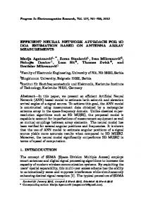
Step 2) Segment the training data into smaller sections. If there have been several consecutive iterations between Steps 2) and 5), then go to Step 6). Step 3) Train and test models individually with segmented data. Step 4) If the accuracy of all the segmented models in Step 3) is satisfied, stop. Else for the segments that have not reached accuracy requirements, proceed to the next steps. Step5) Check for multivalued solutions in model’s training data. If none are found, then perform further segmentation by going to Step 2). Step 6) Train a neural network forward model. Step 7) Using the adjoint neural network of the forward model, divide the training data according to derivative criteria. Step 8) With the divided data, train necessary sub-models,for example, two inverse sub-models. Optionally obtain two competitively trained inverse sub-models and two forward sub-models. Step 9) Combine all the sub-models that have been trained in Step 8).Test the combined inverse submodels. If the test accuracy is achieved, then stop. Else go to Step 7). For further division of data according to derivative information in different dimensions, or if all the dimensions are exhausted, go to Step 2). The algorithm increases efficiency by choosing the right techniques in the right order. For simple problems, the algorithm stops immediately after the direct inverse modeling technique. Figure 6 shows the indirect inverse model of a spiral Inductor. By using the above model and following the steps mentioned the input and output values are represented graphically as shown in figure 7.
Figure. 6. Diagram of indirect inverse model
ISSN : 2229-3345
Vol. 2 No. 3
60
Dr.K.Sri Rama Krishna et al. / International Journal of Computer Science & Engineering Technology (IJCSET)
Figure 7. Comparison of Quality factor Vs Diameter obtained using the simulated results , with that of the neural model (Direct Inverse) of a spiral Inductor.
VI. CONCLUSION Accurate and simple neural models are presented to compute the Quality factor and Diameter of circular spiral Inductor using Forward, Direct Inverse and Indirect Inverse Models. It is shown that Quasi Newton algorithm and Simplex Method are found to be providing better accuracy and suitable for modeling of a spiral Inductor for forward Model and Huber Quasi Newton Algorithm is giving better results for direct inverse Model. It has been observed from figures 5 and 7 that the Indirect Inverse Model is giving better result when compared with the direct inverse model. ACKNOWLEDGMENT We sincerely thank Prof Q J Zhang for his valuable guidance, suggestions and encouragement. REFERENCES [1] [2] [3]
wws2.uncc.edu/tpw/papers/spiral.pdf eprints.utm.my/6147/3/SeeGuanHueiMFKE 2004THP.pdf Q.J. Zhang , K. C. Gupta and Vijay K Devabhaktuni,“Artificial Neural Networks for RF and Microwave Design-from theory to Practice” IEEE Trans. Microwave Theory Tech., vol. 51, pp. 1339-1350, April 2003. [4] Haykin, S., Neural Networks: A Comprehensive Foundation, Macmillan College Publishing Comp., New York, USA, 1994 [5] V. K. Devabhaktuni, M. Yagoub, and Q. J. Zhang, “A robust algorithm for automatic development of neural network models for microwave applications,” IEEE Trans. Microwave Theory Tech., vol. 49, pp.2282–2291, Dec.2001. [6] V. K. Devabhaktuni, C. Xi, F. Wang, and Q.J.Zhang, “Robust training of microwave neural models,” Int. J.RF Microwave Computer-Aided Eng., vol.12, pp. 109–124, 2002. [7] J.Lakshmi Narayana, Dr.K.Sri Rama Krishna and Dr.L.Pratap Reddy, “ Design of Microstrip Antennas using Artificial Neural Networks”, International Conference on Computational Intelligence and Multimedia Applications, SivaKasi,pp:332-334, Dec2007 [8] J.Lakshmi Narayana, Dr.K.Sri Rama Krishna and Dr.L.Pratap Reddy, “ ANN Modles for coplanar strip line analysis and synthesis” , International Journal of Computer Science and Network security, Korea,Vol.8No.10, pp:200-204,Oct 2008. [9] P. M. Watson and K. C. Gupta, “EM-ANN models for microstrip vias and interconnects in dataset circuits,” IEEE Trans. Microwave Theory Tech., vol. 44, pp. 2495–2503, Dec. 1996. [10] J. W. Bandler, M. A. Ismail, J. E. Rayas- Sanchez, and Q. J. Zhang, “Neuromodeling of microwave circuits exploiting space-mapping technology, ”IEEE Trans. Microwave Theory Tech., vol. 47, pp. 2417–2427,Dec. 1999.
ISSN : 2229-3345
Vol. 2 No. 3
61
Dr.K.Sri Rama Krishna et al. / International Journal of Computer Science & Engineering Technology (IJCSET)
[11] P. M. Watson and K. C. Gupta, “Design and optimization of CPW circuits using EM-ANN models for CPW components,” IEEE Trans.Microwave Theory Tech., vol. 45, pp. 2515–2523, Dec. 1997. [12] G. L. Creech, B. J. Paul, C. D. Lesniak, T. J.Jenkins, and M. C. Calcatera, “Artificial neural networks for fast and accurate EM-CAD of microwave circuits,” IEEE Trans. Microwave Theory Tech., vol. 45, pp. 794–802, May1997. [13] A. H. Zaabab, Q. J. Zhang, and M. S. Nakhla, “A neural network modeling approach to circuit optimization and statistical design,” IEEETrans. Microwave Theory Tech., vol. 43, pp. 1349–1358, June 1995. [14] J.Lakshmi Narayana, Dr.K.Sri Rama Krishna and Dr.L.Pratap Reddy “ Performance Evaluation of Neural Models for the Analysis of GaAs MESFET”, GITAM Journal of Information Communication Technology, Vizag, Vol.01, 31-41, 2008 [15] Y. Fang, M. Yagoub, F.Wang, and Q. J. Zhang, “A new macro modeling approach for nonlinear microwave circuits based on recurrent neural networks,”IEEE Trans. Microwave Theory Tech., vol. 48, pp. 2335–2344,Dec. 2000. [16] J. Xu, M. Yagoub, R. Ding, and Q. J. Zhang, “Neural-based dynamic modeling of nonlinear microwave circuits,”IEEE Trans. Microwave Theory Tech., vol. 50, pp. 2769–2780, Dec. 2002. [17] Zhang, Q. J. and K. C. Gupta, Neural Networks for RF and Microwave Design, Artech House, 2000. [18] Christodoulou, C. G. and M. Georgiopoulos,Application of Neural Networks in Electromagnetics ,Artech House, MA, 2001. [19] Guney, K., C. Yildiz, S. Kaya, and M.Turkmen, “Artificial neural networks for calculating the characteristic impedance of air suspended trapezoidal and rectangular-shaped micro shield lines,”Journal of Electromagnetic Wave and Applications, Vol. 20, 1161–1174, 2006. [20] Jin, L. C., L. Ruan, and L. Y. Chun, “Design E plane bandpass filter based on EM-ANN model,” Journal of Electromagnetic Wave and Applications, Vol. 20, 1061–1069, 2006. [21] Mohamed, M. D. A., E. A. Soliman, and M. A. El amal, “Optimization and characterization of electromagnetically coupled patch antennas using RBF neural networks,” Journal of Electromagnetic Wave and Applications, Vol. 20, 1101–1114, 2006. [22] Thomas, V., et al., “A novel technique for localizing the scatterer in inverse profiling of two dimensional circularly symmetric dielectric scatterers using degree of symmetry and neural networks,” Journal of Electromagnetic Wave and Applications, Vol. 19, 2113–2121, 2005. [23] J.Lakshmi Narayana, Dr.K.Sri Rama Krishna and B.Vanajakshi, “ Neural Network Models for Non Linear Devices and Circuits”, International Conference on Computer Commn. and Control,Bangalore,21-25, Nov2006 [24] J.Lakshmi Narayana, Dr.K.Sri Rama Krishna and Dr.L.Pratap Reddy,“ Neural Network Training Algorithms for RF and Microwave applications”, International Conference on Advanced Computing and Communication Technologies,Haryana, 496- 501, Nov 2007 [25] J.Lakshmi Narayana, Dr.K.Sri Rama Krishna and Dr.L.Pratap Reddy, “ANN Structures for RF and Microwave Applications”, International Conference on Recent Applications of Soft Computing in Engineering and Technology, Alwar, 91-98,Dec2007. [26] J.Lakshmi Narayana, Dr.K.Sri Rama Krishna and Dr.L.Pratap Reddy,“ Synthesis and Analaysis of Branch Line Coupler Using Artificial Neural Network Models”, International Journal of Electronics and Communication Engineering, Volume 2, Number 3 (2009),pp.179-192 [27] Dr.K.Sri Rama Krishna , J.Lakshmi Narayana,K.Anusha , “ A Neural Network Modeling Approach for the Analysis of Lange Coupler”, International Journal of Electronic Engineering Research, Volume 2, Number 4 (2010),pp.463-478 [28] Humayun Kabir,Ying Wang, Ming Yu, and Qi-Jun Zhang, “ Neural network Inverse Modeling and applications to Microwave Filter Design”, IEEE Trans. Microwave Theory Tech., vol. 56, No.4, April 2008, pp.867–879.
ISSN : 2229-3345
Vol. 2 No. 3
62