transformation, while the second one carries out the pattern recognition. The entire .... Figure 4: Proposed scheme to obtain i; .variance: the neural zoom.
A NEURAL ZOOM FOR PATTERN RECOGNITION. José M. Quero and Leopoldo García Franquelo. Dpto. Ingeniería. Electrónica, de Sistemas y Automática Escuela Superior Ingenieros Industriales Universidad de Sevilla 41012 Sevilla (Spain)
Phone number: 95 423 62 08 Fax number:
95 462 92 05
ABSTRACT
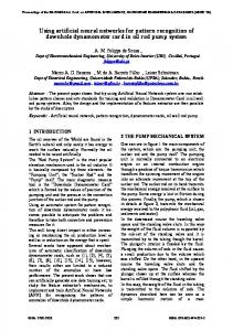
This paper presents the implementation of a space-invariant pattern recognition system based on neural networks. The neural is described as a system composed by two multilayered subnets. The first one performs a space-magnification invariance transformation, while the second one carries out the pattern recognition. The entire system works autonomously using an unsupervised learning scheme. A distributed processor/memory architecture is developed on high-speed, low-cost microprocessors. As a result, an Asynchronous, value-passing connectionist model, easily to be expanded, is obtained. Some simulation experiments applied to the system are described using actual analogical images. The tests show that the system has a high speed of classification, high selectivity and fast self-learning.
Keywords: Invariance Pattern Recognition, Neural Networks, Parallel Processing, Self-Learning Algorithm.
1
INTROD1JCTION
In the area of perception, the human brain is far better than any conventional computer. The present techniques of recognition are highly 'ti::ne-consuming because of the great deal of information involved. However, connectionist models of computation have proven to be promising alternatives to traditional approaches to pattern classification. Motivated by the fact that the power in the brain líes in a high degree of parallelism and concurrency, a great number of connectionist models have been proposed [1 J. They involve a finge number of elemental computations that can be performed in parallel. Although these models are able to learn and recognize patterns, most of them assume that both the learned pattern and the recognized pattern present the same spacial orientation. In this paper a novel scheme to achieve space and magnification invariance pattern recog nition is proposed. A paír oí subnets make up this scheme. Both of them are multilayered nets arrd their design is based upon biologica.l structl1res, characterized by a massively parallel architecture. The first one receives input signa.ls 1'rorn'a matrix oí visual sensors ane! transforms them to obtain a standard representation. 1'his or. ,put is 1'ed into the second subnet which learns 01' recognizes the pattern. The paper is organized as follows. In section 2 the system is described as a pair of in dependent hierarchical neura! networks. First the p.1ttern classificator subnet is introduced. The invariance subnet is also presented as a multilayered network with a control system that ensures the convergen ce 01' the image to its invariance position. Section 3 is devoted to the implementatíon of the system on a multiprocessor architecture, where hardware and software details are given. The next section analyzes the results obtained by training the net with a set of actual images. Learning and recognition time responses and noise rejection ratios are shown. Finally, in section 5 conclusions and suggestions derived from the aboye simulation are outlined.
2
DESCRIPTION OF THE MODEL
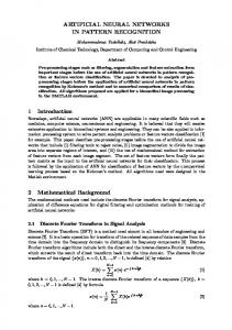
The proposed system is shown in figure l. This sysí;m can be regarded as the association of two independent subnets: the invariance and the pa[¡';~ rn recognition subnets. The first subnet sends its output to the second one whenever it l'eache< an invariant deséription of the object in the image. Below a description of these subnets are;:; :parately given.
2.1
PATTERN RECOGNITION SUBNET
Traditionally, neurons can be described as adaptive filters that sum up their input signals. Each signal is provided with weighing parameters tbat R.da.ptively change according to a learning law. In the proposecl model we apply Hebb's law:if neurOll A repeatec11y contributes to the firing
CONTROL
INVARIANCE SUBNET VISUAL SENSOR
INPUT IMAGE
rATTERN
PA TTERN
RE ,; OGNITION
CLASSIF"ICA TION
'SUBNET INVARIANT IMAGE
Figure 1: Proposed scheme composed by two subr:ets: mvanance and pattern recognition subnets. '1
e
xI
ce "2
cn
Cn / )(,, ~ ~~-~-'-_....../
xn
fn xn--ANV"v----
(o.) Clo.SSiCo.l
neuron
(b) Proposed neuron Moclel
Moclel,
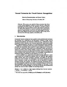
Figure 2: Neuron model used in the ¡:;attern recognition system. The transfer function of the neuron is given by e;¡uation 1
(1)
with
n
r¡
=L
n CiXi
i=l
+ LCiXi
(2)
i::::1
where ciclO, 1] are the weighing parameters, xiE[O,l] are the input signals, Xi and e¡ as the complemented input signals (1 - x;) and their weighing parameters respectively, () is a defined threshold and f is the sigmoid function. The adaptation law of the weighing parameters equation system as follows in (3) . é¡ = ey(C¡ - Xi)
with
el;
i
ls gíven by the first-order clifferentíal
= 1, n
eas the parameter that controls the learning spi;ed.
(3)
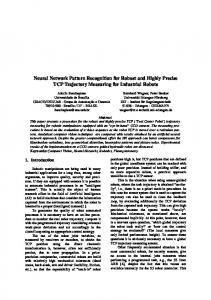
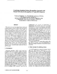
N, nCH'l b er of' nel9 ~borho od s per Io,y er, ni nUMKJ er of neurons per nelghborhoocl, w: nUf'lKJer of conOí?ctlons per ne uron
Lf~
---
-
---.--
......,
--
.--
Re>o.l If'lo.ge L.o,ye r Loco!
1. Feo tures ex tr' oction,
Loyer 2 Gl obol ' ea tures extrac tlo n,
Figure 3: Structure of the pattern reeognition subnet. The pattern recognition subnet has a hierarehical structure consisting of a series of layers of cells [5] as is shown in figure 3. The main differenee between this network and the Fukushima one is that in the latter, neighbouring cells grow 1,0 have input connections of the same spatial distribution than the seed eel! [6]. We propose the :leural zoom to provide space lUvanance reeognition and to prevent the network from learnin¿ redundant information. The object is represented by features that are edraeted in each layer. In the first layer local features are extracted. The degree of loca,lity ; proportionaJ to the relatíve area of the image one neuron analyzes. Global features are ext.rct".: ted in the second layer as an assoeiation of severallocal features. The classification of patterns lS carried out in the deepest layer, where only the neuron with higher output i8 active. Notice that local and global features may be detected in different images, thus preventing the network from learning redundant information. This network works as a pattern classificator with unsupervised learning. Three character istics allow this learning mode:
• Cells in the same layer are grouped in neighborhoods. Neighboring cells receive sig nals from a small area of the previo\1s layer. Each neuron extracts a different local feature. Only the cell yieldíng the maximnm Odtput has its weighíng parameters rein foreed ("winner-takes-·all role") [5] [6]. Therefore this network belongs to the competitive learníng type. • The parameter () that controls the tolerated erre.~ is considered to be the same in all cells of each layer and it increases in the higher one¡" These parameters are chosen according to the rate of noise étnd error acceptable to th r: network. However, on e must take into account that when increasing the tolerated errOl the network presents les s selectivity . • The parameter ~ that controls the learning speed deereases in the deeper layers. In this way we ensure that global features are basee! on stable local ones, thus improving the
down-neuron
)~) up-neur'on Figure 4: Proposed scheme to obtain i; .variance: the neural zoom.
2.2
INVARIANCE SUBNET
A great number oí neural pattern recognition system · onsider the object to be recognized in the same relative position that it had when it was learnt. Fukushima [5] [6 ] proposecl the learning of distorted images so they would be recognized, even if they were deformed. However this solution implies redundancy in the nct, tha{. is, severa) irnages ol' the saIne object are learnt. One method to obtain shift invariance is to use the bidimensional Fast Fourier Transform (B.F.F.T.). The Fourier spectrum is independent from the position of the object in the image. Two objections can be stated: fil'stly F.F.T. has a sel'ious computationaJ burden; secondly F.F,T, does not solve neither the magnifica.tion 1101' the rotation invariance problems . We suggest a more biological1y based system called neural zoom. This system is made up of a hierarchical stl'uctul'e of layers. Each layer receives an image fl'om the pl'evious one (see figure 4), Let k 2 be the value of the magnification pel'formed between each pail' of layers. The number n of layers depends upon the maximum global magniHcation needed.
During the magnification process, four lateral nI !.~TOns control its convergence, Whenever the magnified image reaches the edge, one neuron is 2 ~'tivatecl, Analyzing the possible cases we find that
• None of the lateral neurons is active, therefol'e the magnification pl'ocess continues. • One lateral neuron is active, e.g., one neul'on that detects overflow in the top of the image (up-neuron) . The image is shiftecl to the bottom of the image until the neuron l'esets. The same occurs when the clown, left 01' l'ight neuron activates . • Two non-opposite lateral neurons are activated; horizontal ancl vertical shifts are per formed simultaneous)y. • Opposite neurons a.re simultaneuosly excited. In this case the image has reacheacl its maximum shape. Finishing this process by achieving the equilibl'ium of the pixels.
(x, ,y, /
+ +-j-
r------++--+
tJ±~~+l=~
'------L...L..-..'.J-
Figure 5: Relative areas of the pixels when mapping one layer onto the previous one. pixels that belong to the previous layer. Each weíg 1 ing pararneter can be obtained from the relative are a associated with this connection when rnapping t,he ¡ayer in the previous one, as can be seen in figure 5 Let (Xi, y¡)P be the inclex of the upper leH pixel in the layer p involved by the neuron (Xj, yj)P+l in the layer p+ 1. Without 10ss of generaJity it is assumed that pixels are squares of lateral dimention a. When mapping pixels onto the previous one, they have a size of a/k. The coordinates of the pixel i and the neuron j are (Xi *a, Yi *a)P and (xi*a/ k, Yi*a/ k)p+l. Taking ¡nto account the reJationship between layers, we find ;1:;
t
(4)
y' * a = INT(-'-) + 1 = INT(k * Vi) + 1
(5)
Xj
a/k
[( .Ti -t.1)
-
_
*a
xj=INT( a/k )+l=INT(k*x¡)+l
*a-
Xj
* a/kJU}/i + 1) * a -
Yi
* a/k]
(alA )2 [k*(xi+ 1 )-(INT(k-*x¡)+1)l* [k * (Yi + 1) - (INT(k * !Ji) + 1)] [(Xi
+ 1) * a -
Xj
* a/k][afi~.- (Yi + 1) * a -
(a/k)2 [k * (Xi + 1) - (INT(k * Xi) + 1)] [2 - k * (Yi + 1) + INT(k * yd] 'lUz 1
:::
(6) Yj
* a/k]
*
[2-k*(xi+1)+INT(k*x¡)]* [k * (Yi + 1) ~- (I NT(k * y¡) + 1)]
(7)
(8)
Wn ;:::: [2-k*(x¡+1)+INT(k*x¡)]*
[2 - k * (Yi It can be proved that in the magnification.
Li Lj 'lUij
;::::
+ 1) + 1NT (k * yt) 1
(9)
1, thus providing .'\ normalized value of the pixel obtained
Notice that Wij only depend upon the value ofthe magnificatjon factor k. It has to be calculatecl only once as it remains constant cluríng the magnífication process .
Figure 6: Area analyzed by the lateral control neuron.
5 i
r- I
2
1---+---1
f,
7
-'
I
3 Figure 7: Implementation of the neural network on a multiprocessor architecture. receive input signals from an area of size 1, as shown in figure 6, where
1 = m a - m a/k 2
3
=m a k -
1
2k
(lO)
IMPLEMEl\'TATION
The network presented in section 2 has been implemented on a multiprocessor architecture using an array of 10 transputers [7]. The architecture used is shown in figure 7, Each layer of the network is mapped onto an array of processors. In the host processor the inputs and the outputs of the network are managed. The invariance transformation of the image and the local features extraction are carried out in the processors 1 to 6. In processors 7 and 8 the global
•
1: Input process IT Inv o rionc é Tron s f o rrw tion PR: Po t te r n l:;:' ec o g ni t ¡O n O [Ju tpu t pro c e s s
Figure 8: Parallel processes in c'I,ch micropro cessor. neural network. A diagram of the processes that "0Drk in parallel in each processor can be seen in figure 8. The input process I receives tbe ¡no ming data from the four input links and determines where the information shonlcl be forwardc! l. The processes IT ancl PR carry out the invariance transformation ane! the pattern rccognitl< n respectively. A rou tíng algorithm has been implemented on the output proccss O. This algcrithm decides which link the informatíon should be sent by, according to a table in the memory that has previously been calculated by the shortest path routing algorithm [8J. The set of processors that simultf\.neollsly perform th e Ínvariance transformation and the local feature extra.ction have their pl'ocesses working in an alternative mode. Whenever the Ínvariance transformation converges, it sends its output to the local feature extraction processes . Every layer receives the output signals from the prevÍous one. Because of the aim of this architecture is to provide an asynchronous simulation of the network, processes working as interfaces for the incoming and outgoing data have been used in paraJlel with the neurons. The use of these communication interfaces also avoíd bot t l(onecks and deadlocks in communication.
4
SIMULATIOl\T RESULTS
The network has been tested using real 255x255-pixE ' images. These images have been taken with a video digitizer system. Each pixel is cocled in' a,n S-bit word, yielding 256 gray levels o They have not been pre-processed, although it is assumed that the object is recognizable from the background [9J. Figure 9 represents exampl es of these im ages , becau se of t he quality of the hardcopy, only four gray levels have been usecl Figures 9.a-e illu strate fiv e examples of the objects that have been used. Two of thern are very similar while the others are quite different . The network was consecutively fed with sixteen different images, AH of these images were correctiy learned and recognized. In order to test the network 's performa.nce, sorne noisy images were introduced. These images were obtained by adcling white noise to all pixels with an amplitude randomly ranging from O to 20% of their maximum intensity, and they were correctly recognized . Examples of
(a)
(e)
(b)
(d)
•
(e)
'"
,,
1.
" ,:i' :
.':
:",
. .. .
:
I
(í)
:"t ,: " "
I
~
(g)
-'
..
(h)
Figure 9: Several examples oí the actual in ,ages used to test the network.
nOlse 0%
20;.
[0%
0%
10%
/:/ /;(
30%
(h
/:
;(/
:/
:/~ /%%>/
40% 50%
// / /~X / . / //1 /
60/; - 70 :


![[PDF]EPUB Neural Networks for Pattern Recognition READ ONLINE ...](https://m.moam.info/img/260x300/pdfepub-neural-networks-for-pattern-recognition-re_647859cf097c4744708cbbaf.jpg)