Jurnal Teknologi
Full paper
A New Improved Walsh Function Algorithm for Active and Reactive Power Measurement Garba Aliyua*, Saifulnizam Abd. Khalida, Jafaru Usmana, Ahmad Fuad A. Aziza, Hussein Shareefb aDepartment bFaculty
of Electrical Power System, Faculty of Electrical Engineering, Universiti Teknologi Malaysia, 81310 UTM Johor Bahru, Johor, Malaysia of Electrical Engineering and Build Environment, Universiti Kebangsaan Malaysia, 43600 Bangi, Selangor, Malaysia
*Corresponding author:
[email protected]
Article history
Abstract
Received :23 October 2013 Received in revised form : 14 December 2013 Accepted :10 January 2014
1
This paper present improved Walsh function (IWF) algorithm as an alternative approach for active and reactive power measurement in linear and nonlinear, balanced and unbalanced sinusoidal three phase load system. It takes advantage of Walsh function unified approach and its intrinsic high level accuracy as a result of coefficient characteristics and energy behaviour representation. The developed algorithm was modeled on the Matlab Simulink software; different types of load, linear and nonlinear were also modeled based on practical voltage and current waveforms and tested with the proposed improved Walsh algorithm. The IEEE standard 1459-2000 which is based on fast Fourier transform FFT approach was used as benchmark for the linear load system while a laboratory experiment using Fluke 435 power quality analyzer PQA which complies with IEC/EN61010-1-2001standards was used to validate the improved algorithm for nonlinear load measurement. The results showed that the algorithm has the potential to effectively measure three phase power components under different load conditions.
0
Keywords: Walsh function; reactive power; nonlinear load; measurement; fast Fourier transform
-1
Abstrak
Graphical abstract 3 Qsin(4t) Wal(7,t)
Current(A)
2
-2
-3
0
0.002 0.004 0.006 0.008 0.01 0.012 0.014 0.016 0.018 0.02 Time(s)
Kertas ini membentangkan algoritma fungsi Walsh tertingkatkan sebagai pendekatan alternatif bagi pengukuran kuasa aktif dan reaktif dalam sistem beban sinus tiga fasa yang dan tak lelurus serta seimbang dan tidak seimbang. Kelebihan pendekatan fungsi Walsh adalah bersepadu dan ketepatannya bertahap tinggi yang hakiki yang disebabkan oleh ciri-ciri pekali dan perwakilan sifat tenaga. Algoritma yang dibina ini dimodelkan di perisian Matlab Simulink; jenis beban yang berlainan, linear dan tak linear juga dimodelkan berdasarkan gelombang voltan dan arus praktikal serta diuji dengan menggunakan algoritma Walsh tertingkatkan seperti yang dicadangkan. Standard IEEE 1459-2000 berasaskan pendekatan gubahan Fourier pantas FFT digunakan sebagai penanda aras bagi sistem beban lelurus manakala satu ujikaji makmal menggunakan Fluke 435 penganalisi kualiti kuasa PQA yang menepati standard IEC/EN61010-1-2001 telah digunakan untuk mengesahkan algoritma tertingkatkan ini bagi pengukuran beban tak lelurus. Hasil kajian menunjukkan bahawa algoritma ini mempunyai potensi untuk mengukur komponen kuasa tiga fasa bg keadaan beban berbeza secara berkesan. Kata kunci: Fungsi Walsh; kuasa reaktif; tak lelurus; pengukuran; jelmaan Fourier pantas © 2014 Penerbit UTM Press. All rights reserved
1.0 INTRODUCTION As the awareness of the problems associated with nonlinear devices and their influence on power components measurement increases, the use of these power electronics equipment and appliances with microprocessors have been proved to considerably contribute to the distortion of the waveform of the supply system at the distribution end.1 These distortions increase the reactive power of the system and lower the power factor which invariably has negative effect on the power quality of the supply system. Accurate measurement and evaluation of energy
consumption is of utmost importance for effective planning, billing, monitoring, maintenance and further development of the power supply system. The deregulation of the power sector and the increasing cost of fossil fuel have led electricity operators to seek for ways to make the best use of the supply systems. Proper evaluation of the energy consumption is one of the important tasks in electric power industries, especially in electric bill and the electrical energy quality estimation and control.2,3 Several companies are into design and manufacture of energy meter to meet the increasing demand of smart metering.4 In the pricing of electric bill based on the value of the integral of the load active
67:3 (2014) 1–8 | www.jurnalteknologi.utm.my | eISSN 2180–3722 |
Garba Aliyu et al. / Jurnal Teknologi (Sciences & Engineering) 67:3 (2014), 1–8
power measured using kilowatt-hour meter, the electric utility board incurs losses in revenue for energy delivered to current harmonic generating customers and also those that cause current asymmetry.5 Most times, customers that do not generate harmonics but are supplied with distortion / asymmetrical voltages are billed not only for the useful energy but also for the energy which may have caused malfunction of their equipment.6 The IEEE working group on appropriate determination of billing system based on sinusoidal and non-sinusoidal situation defined distortion power in terms of total fundamental and harmonic constituents with less unwieldy theory.7 The conventional or classical method of determining power consumption is to evaluate using measured values of the voltage, current and power factor. The apparent power, active power, and reactive power are defined as in reference.8 This classical way of power evaluation needs accurate measurement of the root mean square (RMS) values of the voltage and current before performing the multiplication operation so as to determine the apparent power. Precise determination of RMS values of voltage and current is complex and poses a serious challenge in electrical measurement.9 For the classical method of power calculation to be effective in a three phase network the following has to be satisfied; (i)
Voltages and current RMS values on all the three phases must be identical. (ii) Phase angles between voltage and current should always be 120o and are time invariant. These conditions may not be attainable in the real practical world due to the nature of the loads most of which are nonlinear.10 This paper proposed improved algorithm as an alternative for power component measurement process using the Walsh function which has the advantage of better accuracy and reliability in energy measurement as it takes into consideration among others, elimination of the effect of harmonic on reactive power measurement. Walsh function transform algorithm has a unique and essentially high level accuracy as a result of coefficient characteristics and energy behaviour representation.11 The method can be used on any type of energy meter testing. The remaining of this paper is organized as follows. Section two, presents Walsh function and its analytical expression, while section three highlights the steps involved in the development of the proposed improved algorithm for measurement using the Walsh function, section four has the modeling and simulation of the improved algorithm, five is the simulation and laboratory experiment results, Lastly, section six is the conclusions.
harmonics to the measurement results which was not accounted for was the main setback of the algorithms.12-14 The attractions to Walsh function based technique for use in energy parameter evaluation are; (i)
The Walsh transforms analyzes signals into rectangular waveform rather than sinusoidal ones and is computed more rapidly when compared with Fourier transform FT. (ii) Walsh function based algorithm contains addition and subtractions only and hence result in considerably simplified hardware implementation of power evaluation. (iii) The IEEE/IEC definition of a phase shift between the voltage and the current signal mainly use for reactive power evaluation is eliminated from signal processing operation when using Walsh function.15 Generalized Walsh functions and transforms was introduced in 1923 by J.L. Walsh but their application to engineering and other fields did not happen until recently16 with some basic and enlightening properties of these function considered. These functions can be applied ‘inter alia’, to develop algorithm that would be applicable to nonlinear load problem analysis. It is a full orthogonal system with unique properties, which include that it has only two values +1 and -1 over specified normalized period T. This greatly influences the effectiveness of signal processing operation as related to measurement of power components and characteristics of power distribution system. Analytically the Walsh function is expressed as; m
( nmk 1 imk ) k
Wal (n, ) (1) k 1 Where;
mth coefficients of the n represented in binary code i.e. n (n0,n1, n2, n3....nm )2 , nm 0,1. With m being the highest-order
WF serial number in the system, is the argument of WF that defines the coefficients of k in binary code (k , k ...k )2 ,
k 0,1 and k 1,2,3...m. From equation (1) the graphical representation of the first fourth order Walsh function is generated as shown in Figure 1. 1 0 -1
Wal(0,t)
ANALYTICAL
The Walsh function method for the analysis and evaluation of nonlinear signals was presented as a mathematical tool to analyze energy parameters output behaviour for in-depth error detection; the method is faster when compared with other techniques like FFT. It does not require the phase shift between voltage and current and it has less computation requirement.8 However, when the load becomes nonlinear the distorted voltage and current waveform produces harmonic which is a multiple of the fundamental frequency of the current and/or voltage. Harmonic current affects the reactive power measurement so another attempt using modified approach for power components measurement in both sinusoidal and non-sinusoidal condition was made, the approach reduced computational demand, though the influence of
(Amp)
(WF)
(Amp)
FUNCTION
(Amp)
0
2.0 WALSH EXPRESSION
(1)
n is the order of the function form n 1,2,3...nm which is the
(Amp)
2
0.002 0.004 0.006 0.008
0.01 0.012 0.014 0.016 0.018 Time(s)
1 0 -1
0.02
Wal(1,t) 0
0.002 0.004 0.006 0.008
0.01 0.012 0.014 0.016 0.018 Time(s)
0.02
0
0.002 0.004 0.006 0.008
0.01 0.012 0.014 0.016 0.018 Time(s)
0.02
2 0 -2
Wal(2,t)
2 0 -2
Wal(3,t) 0
0.002 0.004 0.006 0.008
0.01 0.012 0.014 0.016 0.018 Time(s)
0.02
Figure 1 Graphical representation of first fourth order WF
3
Garba Aliyu et al. / Jurnal Teknologi (Sciences & Engineering) 67:3 (2014), 1–8
3.0 WALSH FUNCTION ALGORITHM
Qc
The IEEE standard 1459-2000 for the instantaneous voltages ( va ,
vb , vc ) and currents ( ia , ib , ic ) in a three phase distribution network with linear balanced or unbalanced loads is given as;17 Instantaneous three phase sinusoidal voltages. va 2Va sin(t ) vb 2Vb sin(t 120)
(2)
vc 2Vc sin(t 120)
Instantaneous three phase currents
T
2T
[ pcWal (3, t )dt Pc 3] 0
The algorithm for real or active powers in the three phase a, b and c is determined by multiplying equations (5) by the zero order Walsh function i.e. Wal (0, t ) and integrate over the period T. In Walsh algorithm the zero order function Wal (0, t ) 1 , over the period of T as can be seen from Fig.1 so all the integral terms at the right hand side of equations (5) that involve product of Wal (0, t ) with the cos(2t ) and sin(2t ) approach to zero thus giving equations (7) as; T
T
T
T
1 1 [ paWal (0, t )dt ] [ Wal (0, t ) Pa dt T 0 T 0
ia 2I a sin(t a ) ib 2I b sin(t b 120)
(3)
ic 2I c sin(t c 120)
1 1 [ pbWal (0, t )dt ] [ Wal (0, t ) Pbdt T 0 T 0 T
Where; Va , Vb , Vc and I a , I b , I c are the RMS values of the line to neutral voltages and currents for the phases a, b and c respectively. a , b and c are the phase angles between the respective voltage and current. 2 f , f = Frequency Hz, t = 1/f. The instantaneous powers for the three phases represented with say pa , pb and pc are given by;
(7)
T
1 1 [ pcWal (0, t )dt ] [ Wal (0, t ) Pc dt T 0 T 0 Solving the equations further active powers Pa , Pb and Pc are obtain for three phase power system as shown in equations (8). T
Pa
1 Wal (0, t ) pa dt T 0
(4)
Pb
1 Wal (0, t ) pb dt T 0
Substituting for ( va , vb , vc ) and ( ia , ib , ic ) in the above expressions and solve trigonometrically the instantaneous powers for phase a, b, and c of the three phase linear balanced and unbalanced load network are derived as in equations (5).
Pc
1 Wal (0, t ) pc dt T 0
T
pa va ia , pb vb ib and pc vc ic
pa Pa [ Pa cos(2t ) Qa sin(2t )] pb Pb ( Pb 3Qb )cos(2t ) ( Pb 3 Qb )sin(2t )
(5)
pc Pc ( Pc Qc 3)cos(2t ) (Qc Pc 3)sin(2t )
Where; Pa Va I a cosa , Pb Vb Ib cosb , Pc Vc I c cosc
Qa Va I a sina , Qb Vb Ib sinb and Qc Vc I c sinc respectively. The algorithm for measuring the reactive powers on these three-phase system says, Qa , Qb and Qc using the Walsh function is obtained by multiplying both sides of equations (5) by the third order Walsh function Wal (3, t ) and integrating over the period T of power system frequency to obtain equations (6). The integral of the third order WF with a constant and a multiply of cos(2t ) is equal to zero. cos(2t ) is orthogonal with the Walsh function so the result is as shown in equations (6).
Qa Qb
T
2T
2T
[ paWal (3, t )dt ] 0
T
[ pbWal (3, t )dt Pb 3] 0
(6)
(8)
T
The modeling and simulation of equations (6) and (8) has been implemented earlier in12 and it shows that current harmonic affects the reading of the simulation results. The algorithm has to be further improved as to be able to measure the power components in both linear and non-linear sinusoidal nonsinusoidal load conditions. It is worthy to note at this juncture, that in AC network source voltages are relatively pure sinusoidal waveforms. It is at the distribution that harmonic are introduced due to the increasing use of nonlinear load like computers, fluorescent lamps, adjustable speed drive motors, arc furnaces, arc welding machines, electronic control and power converters among others. Harmonic current causes overloading of neutral conductors, overheating of transformers, tripping of circuit breakers, power factor correction capacitors over stress and skin effects.18 Also other research have shown that the effect of odd harmonic is more significant in power distribution system while that of even harmonic is negligible.19-22 3.1 Improved IWF Algorithm for Measurement Harmonic in the power system does not have much effect on the active power measurement but has a great deal of influence on the reactive power which invariably affect the power factor and hence the quality of the supply system. To derive the improved Walsh function IWF algorithm for measurement we assume that the load current is contaminated with say, third order current harmonic denoted as ia 3 , ib 3 and ic 3 with a 3 , b 3 and c 3 being the phase angle between the fundamental voltages and the third order current harmonic waveforms of the phases. I a 3 , I b 3 and I c 3 are
4
Garba Aliyu et al. / Jurnal Teknologi (Sciences & Engineering) 67:3 (2014), 1–8
the RMS values of the third order current harmonic as given below;
ia3 I a3 sin(3t a3 )
Qc
The instantaneous powers pa3 , pb3 and pc3 for the three phases a, b and c under this condition are derived as shown in equations (10);
pa3 Pa (Pa3 Pa )cos(2t ) (Qa3 Qa )sin(2t ) Pa3 cos(4t ) Qa3 sin(4t ) pb3 Pb ( Pb3 Pb 3Qb )cos(2t )
(Qb3 Pb 3)sin(4t )
(10)
sin(4t) the constant are all equal to zero. Hence equation (11) becomes;
1 T
T
0
T
p Wal (3, t )dt P c
2T
3 Qc 3
c
0
terms,
i.e. Qa3 sin(4t ) ,
(Qb3 Pb 3)sin(4t )
and
3 Qsin(4t) Wal(7,t)
Current(A)
0
-1
-2
-3
0
0.002
0.004
0.006
0.008
0.01 0.012 Time(s)
0.014
0.016
0.018
0.02
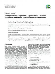
Figure 2 Oscillating frequency of Q sin(4t ) and . To estimate these distortions power terms we multiply both sides of equation (10) by the 7th order WF and then integrate over the period T and simplify to obtain equation (14) T
1 ( Pb 3Qb 3 Qb )sin(2t )Wal (3, t ))dt T 0 T
T
(13)
T 1 paWal (7, t )dt 1 Qa 3 sin(4t )Wal (7, t ))dt T 0 T 0
T
1 Wal (3, t )(Qa 3 Qa )sin(2t )dt T 0
b
3 Qb 3
b
1
Qa3 Va I a3 sina3 , Qb3 Vb Ib3 sinb3 and Qc3 Vc Ic3 sinc3 respectively. To obtain the improved algorithm for reactive power under this harmonic condition we apply the Walsh function by multiplying equations (10) with the third order Walsh function i.e. Wal (3, t ) and integrate over the time T. According to the Walsh functions all the integrals of the right hand side terms of equation (10) that involves the multipliers of cos(2t ) , cos(4t ) ,
p Wal (3, t )dt
b
0
2
Where; Pa3 Va I a3 cosa3 , Pb3 Vb Ib3 cosb3 Pc3 Vc I c3 cosc3 ,
T
p Wal (3, t )dt P
4 which is similar to the oscillating frequency of the 7th order WF, Wal (7, t ) as can be seen in the Figure 2.
(Qc3 Pc 3)sin(4t )
0
a3
Qa 3 , Qb 3 and Qc 3 in equations (13) are the reactive components of the distortion power in the phases, this indicates the influence of the third order current harmonics , and on the reactive power measurement algorithm. The third order Walsh function eliminates the effect of the third order harmonics of the nonlinear load. The final terms of equations (10) are the distortion
( Pc 3 Qc 3 Qc )sin(2t ) ( 3Qc 3 Pc 3 )cos(4t )
1 T
a
0
(Qc3 Pc 3)sin(4t ) they are oscillating with the frequency of
pc3 Pc ( Pc 3 Pc 3Qc )cos(2t )
paWal (3, t )dt
p Wal (3, t )dt Q
T
2T
power
( Pb 3 Qb3 Qb )sin(2t ) ( 3Qb3 Pb3 )cos(4t )
T
(9)
ic3 I c3 sin(3t c3 120)
T
2T
Qb
ib3 Ib3 sin(3t b3 120)
1 T
Qa
1 0 pcWal (3, t )dt T 0 ( Pc 3Qc3 Qc )sin(2t ) Wal (3, t )dt
1 T
T
1 T
T
p Wal (7, t )dt b
0
p Wal (7, t )dt c
0
T
1 (Qb 3 Pb 3)sin(4t )Wal (7, t ))dt T 0 T
1 (Qc 3 Pc 3)sin(4t )Wal (7, t ))dt T 0
(14)
(11) The product of (Qa3 Qa )sin(2t ) ,
the
3rd order WF with the ( Pb 3 Qb3 Qb )sin(2t ) or
( Pc 3 Qc3 Qc )sin(2t ) result in the full wave rectification of the terms. 1 T 1 T
T
1 T
T
T
paWal (3, t )dt 0
pbWal (3, t )dt 0
1 T
T
1 (Qa 3 Qa )sin(2t )dt T 0
T
1 0 pcWal (3, t )dt T 0 ( Pc 3 Qc3 Qc )sin(2t )dt
Solving for Qa , Qb and Qc
T
1
(12)
T
p Wal (7, t )dt T Q a
a3
0
sin(4t )dt
0
T
T
1 ( Pb 3 Qb 3 Qb )sin(2t )dt T 0
The 7th order WF is the odd function with the frequency similar to the frequency of the distortion terms Figure 2. The product of the 7th order WF with the distortion terms results in their rectification. So taking cognizance of these rectifying effects, equations (14) is written as in equation (15).
T
1 1 pbWal (7, t ))dt (Qb 3 Pb 3)sin(4t )dt T 0 T 0 T
T
1 1 pcWal (7, t )dt (Qc 3 Pc 3)sin(4t )dt T 0 T 0
Solving for Qa 3 , Qb 3 and Qc 3 produces equations (16)
(15)
5
Garba Aliyu et al. / Jurnal Teknologi (Sciences & Engineering) 67:3 (2014), 1–8 Qa 3
2T
Qb3
2T
waveform, so these integrals are not equal to zero. This equation is written as in equations (18);
T
p Wal (7, t )dt a
0
T
p Wal (7, t )dt P b
b
(16)
0
T
T 1 1 ( paWal (3;7, t )) dt (Wal(3;7, t ))(Qa 3 Qa )sin 2tdt T 0 T 0
T
p Wal (7, t )dt P 2T
Qc 3
3
c
c
T
1 Wal (3;7, t )Qa 3 sin 2tdt. T 0
3
0
T
Equation (16) is the proposed improved Walsh function algorithm for measuring the distortion power in a three phase system. Substituting in equation (13) gives an algorithm for reactive powers shown in equations (17) Qa
2T
T
T
T
0
0
1 ( pbWal (3;7, t )) dt T 0 T
1 (Wal(3;7, t ))( Pb 3 Qb 3 Qb )sin 2tdt T 0 T
1 (Wal (3;7, t ))(Qb 3 Pb 3)sin 4tdt. T 0
[ paWal (3, t )dt paWal (7, t )dt ] T
T
Qb [ pbWal (3, t )dt pbWal (7, t )dt ] 0
0
T
T
0
0
(18)
(17)
1 ( pcWal (3;7, t )) dt T 0 T
1 (Wal (3;7, t ))( Pc 3 Qc 3 Qc )sin 2tdt T 0
Qc [ pcWal (3, t )dt pcWal (7, t )dt ]
T
This algorithm eliminates the effect of the 3rd and 7th order harmonics on the reactive power measurement and also essentially reduced the effect of the higher order current harmonics. In other to reduce the computation involved, the 3rd and 7th order Walsh are added together which gives a new improved algorithm. The analytical addition of the 3rd and 7th is represented in Figure 3.
(A)
1
Wal(3,t)
0
0
0.002 0.004 0.006 0.008
1
(A)
Solving the right hand side integrals of equations (18) yields the new improved algorithm in equations (19). T Qa paWal (3;7, t ))dt T0
Qb
a
-1
0.01 0.012 0.014 0.016 0.018 Time(s)
0.02
Wal(7,t)
0
b
-1 0
0.002 0.004 0.006 0.008
2
(A)
1 (Wal (3;7, t ))(Qc 3 Pc 3)sin 4tdt. T 0
0.01 0.012 0.014 0.016 0.018 Time(s)
0.02
Wal(3;7,t)
0
c
Qc
T
T
T
p Wal (3;7, t )dt (P b
b
3 Qb3 )
(19)
0
T
p Wal (3;7, t )dt (P c
c
3 Qc 3 )
0
Equations (7) and (19) above are the proposed improved Walsh function algorithms that would be used to measure the active, distortion and reactive power respectively of a network and also eliminate the effect of higher order harmonic in the three phase reactive power measurement system. Suffice it to say that in actual cases only lower order harmonics are present in power system signal.
-2 0
0.002 0.004 0.006 0.008
0.01 0.012 0.014 0.016 0.018 Time(s)
0.02
Figure 3 (a) Wal 3, t (b) Wal 7, t and (c) Wal 3;7, t
From Figure 3 it can be observed that the proposed IWF as a result of the addition of standard 3rd and the 7th order WF is defined as follows; Wal 3;7, t is +1, if t is in the interval [0; T/8], [T/2; 5T/8] 0, if t is in the interval [T/8; 3T/8], [5T/8; 7T/8] -1, if t is in the interval [3T/8; T/2], [7T/8; T] The new improved WF is derived by multiplying equations (10), with Wal 3;7, t and takes the integral over the time T. Now considering the integrals after the equal sign, pa , pb and pc are constants so are equal to zero because IWF is a periodic function, 2nd and 4th integrals are also equal to zero as they include cosine functions that are orthogonal with the IWF. The 3rd and 5th integrals comprise the rectification of the sine functions
4.0 MODELING THE PROPOSED IWF ALGORITHM Equations (7) and (19) are used to create the model for the active and reactive power measurement based on the proposed improved algorithm using the Matlab Simulink software tool. Some of the commonly used nonlinear domestic loads were modeled along and use in the simulation of the proposed improved Walsh function algorithm for active and reactive power measurement examples, compact fluorescent lamps (CFL) and computers, The loads can be resistive R, inductive L, capacitive C or a combination e.g. RL, RC, LC, RLC depending on the type of load being modeled. RL was used to model the loads used in this experiment.
6
Garba Aliyu et al. / Jurnal Teknologi (Sciences & Engineering) 67:3 (2014), 1–8 250
150
Wal(0,t) 1
1 V
Fourier Gain
Phase -KDiscrete V_Fundamental
50 0 -50
Deg->Rad -100 -150
K Ts
1
z-1 Discrete-Time Integrator
Mag
I
P
cos
sin
2
100
1
Voltages
Mag
Va Vb Vc
200
Walsh Code Generator
Gain1
2
-200
Q -250
0
0.02
0.04
0.06
0.08
Out1
Fourier
0.1 T(sec)
0.12
0.14
0.16
0.18
0.2
Figure 6 3-phase sinusoidal voltage waveform
Phase Wal(3;7,t) Discrete I_Fundamental
8 Ia Ib Ic
6
Figure 4 The Subsystem of the proposed model
4
R Current(A)
2 0 -2 -4
C
L
-6 -8
0
0.02
0.04
0.06
0.08
0.1 T(sec)
0.12
0.14
0.16
0.18
0.2
Figure 7 3-phase unbalanced load current waveform
Figure 5 Model of nonlinear load
The RL nonlinear loads were modeled using universal bridge rectifier; the values for the Rs and Cs were determined using the expressions:Rs 2Ts Cs and Cs Pn 1000(2 f )Vn2 Where Pn = nominal power of three phase converter VA
Vn = nominal line AC voltage V rms f = fundamental frequency Hz Ts = Sample time.
The R and L of an RL load is calculated using data recorded on the standard fluke power quality analyzer during the experiment. 5.0 SIMULATION AND EXPERIMENTAL RESULTS For the simulation of the linear loads a synthetic line to neutral voltages (V phases) were chosen as follows;
Va 22000 , Vb 2201200 and Vc 2201200 Load impedances for two different cases of unbalanced three phase system are chosen as shown in case A and B below for the simulation to verify the algorithm. Knowing the supply voltage and the impedance of the loads (Z) the resistance (R) and inductance (L) of each phase load was calculated and the obtained results for R and L was used to configure standard RLC load taken from the Matlab simulink power blocks. Case A: Za 36 j 20; Zb 55 j15; Zc 15 j11 Case B: Za 25 j 20; Zb 17 j 60; Zc 18 j38
Figure 6 and 7 shows the voltage and current waveform for the three phase sinusoidal linear unbalanced load system obtained from simulation with the new improved algorithm. 5.1 Linear Load System For the linear sinusoidal load system, IEEE standard 1459-2000 which is based on FFT approach was used as benchmark for measurement of active and reactive power of case (A) for the three phases and compared with the results using the proposed improved algorithms (7) and (19). The results are displayed in Table 1. Similarly for case (B) is shown in Table 2. From the results using the IEEE standard 1459-2000 which is based on FFT as reference it can be observed that the proposed Walsh function algorithm captured the active and reactive power with a high degree of accuracy. Table 1 The result of case A Active Power FFT Approach P (watts) Phase a 1181.1 Phase b 214.1 Phase c 492.6 Total 1887.8 Proposed IWF Method Phase a 1180.7 Phase b 214.8 Phase c 493.5 Total 1889
Reactive Power Q (var) 944.8 746.5 1039.1 2730.4 944.5 746.7 1040.2 2731.4
Table 2 The result of case B FFT Approach Active Power P (watts) P (watts) Phase a 1027.5 Phase b 819.3 Phase c 2098.6 Total 3945.4 Proposed IWF Method Phase a 1028 Phase b 818.6 Phase c 2099 Total 3945
Reactive Power Q (var) 569.5 223.3 1538.9 2331.7 569.6 223.8 1539 2332.4
7
Garba Aliyu et al. / Jurnal Teknologi (Sciences & Engineering) 67:3 (2014), 1–8
5.2 Nonlinear Harmonic Load The modeling of the nonlinear loads was based on the readings recorded for the various nonlinear loads using the fluke PQA meter that is in compliances with IEC/EN61010-1-2001standards. The computer and CFL lamps were modeled as RL loads and simulated using both FFT approach and the proposed improved Walsh algorithm for the measurement of active and reactive power using the laboratory experimental results as benchmark. The non-linear load currents waveform for the experiment using the Fluke PQA meter and that of the model simulation is recorded as shown in Figure 8 and 9. The result of the simulations and experimental measurement of nonlinear loads are presented in the Table 3. It can be observed that the standard FFT approach recorded significant error which is due to the spectral leakage and picket fence effect phenomenon of the FFT approach when used for measurement in nonlinear harmonic load system. On the other hand the proposed improved Walsh function algorithm for measurement gave a near accurate result as the influence of the harmonic of the nonlinear harmonic load has been address by the proposed improved Walsh algorithm.
Figure 8 Nonlinear current waveform (experiment).
Non linear load current waveform 200
Current(A)
100 0 -100 -200
0
0.02
0.04 0.06 Time(s)
0.08
0.1
Figure 9 Nonlinear current waveform (simulation)
Table 3 Simulation and Experimental results
S/N
Load Type
1 2 3 4
CFL lamps (15.8watts x 45) Desktop computers (60.3watts x 70) Laptop computers (54.6 watts x 8) 2ft. fluorescent lamps (27.8watt x 15)
Fluke 435 PQA meter Readings P Q (watts) (var) 711 364.5 422.1 20.3 436.8 18.5 417 934.5
FFT Approach P (watts) 710.8 421.9 435.7 416.3
6.0 CONCLUSION
References
A new improved Walsh function algorithm for active and reactive power measurement was presented. The IEEE standard 14592000 fast Fourier transform approach was used as benchmark to validate the algorithm when the load system is linear and sinusoidal. The Fluke 435 power quality analyzer PQA meter was used as reference for nonlinear harmonic load system measurement. The results shows that the proposed improved Walsh function has the potentials of accurately measuring power component under different load conditions. If the algorithm is integrated into measuring instrument it would be able to properly record the active and reactive power of consumers for proper billing purposes and maintenance planning. The research is continuing in the development of a model for measuring the distortion component of the power system.
[1]
[2]
[3]
[4]
[5]
[6]
Acknowledgement This research was supported by the Ministry of Higher Education Malaysia through the Universiti Teknologi Malaysia Research Development Centre.
[7]
Q (var) 363.4 19.8 18.3 933.8
Proposed IWF algorithm P Q (watts) (var) 711 364 422 20 437 18 417 934
E. B. Makram, R. B. Haines, and A. A. Girgis. 1992. Effect of Harmonic Distortion in Reactive Power Measurement. IEEE Transactions on Industry Applications. 28(4): 782–787. A. Abiyev. 2010. Measurement of Reactive Power in Unbalanced Threephase Power Systems by Use of Walsh Functions. International Journal of Academic Research. 2(4): 46–56. L. S. Czarnecki. 2006. Instantaneous Reactive Power p-q Theory and Power Properties of Three-phase Systems. IEEE Transactions on Power Delivery. 21(1): 362–367. S. Toral, J. Ouero, and L. Franquelo. 2001. Reactive power and energy measurement in the frequency domain using random pulse arithmetic. IET IEE Proceedings on Science, Measurement and Technology, March. 148(2) p. 63-67. A. Ozdemir, and A. Ferikoglu. 2004. Low Cost Mixed-signal Microcontroller Based Power Measurement Technique. IET IEE Proceedings-Science, Measurement and Technology July 4. 151(4): 253– 258. R. Langella, and A. Testa. 2007. A New Algorithm for Energy Measurement at Positive Sequence of Fundamental Power Frequency, Under Unbalanced Non-Sinusoidal Conditions. IEEE in Power Technology, July 1-5. Lausanne. 1558–1563. A. Brandolini, A. Gandelli, and F. Veroni. 1994. Energy Meter Testing Based on Walsh Transform Algorithms. IEEE Proceedings of 10th Anniversary and Advanced Technologies on Instrumentation and Measurement Technology Conference, IMTC. May 10-12. Hamamatsu: 3. P. 1317–1320.
8 [8]
[9]
[10]
[11]
[12]
[13]
[14]
[15]
Garba Aliyu et al. / Jurnal Teknologi (Sciences & Engineering) 67:3 (2014), 1–8 T. Lin, and A. Domijan Jr. 2006. Recursive Algorithm for Real-time Measurement of Electrical Variables in Power Systems. IEEE Transactions on Power Delivery. 21(1): 15–22. W. M. Lin, and T. C. Ou. 2011. Unbalanced Distribution Network Fault Analysis with Hybrid Compensation. IET Generation, Transmission & Distribution. 5(1): 92–100. W. G. Morsi, M. El-Hawary. 2011. Wavelet-Based Reactive Power and Energy Measurement in the Presence of Power Quality Disturbances. IEEE Transactions on Power Systems. 26(3): 1263–1271. R. H. Abiyev, A. N. Abiyev, and K. Dimililer. 2007. The Walsh Functions Based Method for Reactive Power Measurement. IEEE 33rd Annual Conference of the Industrial Electronics Society, IECON November 5-8. Taipei. 233–2342. M. Maqusi. 1972. On Generalized Walsh functions and transform. Proceedings of IEE Decision and Control 11th Symposium on Adaptive Processes December 13-15. 11: 499–502. A. N. Abiyev. 2008. A New Electronic Reactive Power Meter based on Walsh Transform algorithms. IEEE/PES Conference and Exposition in Transmission and Distribution April 21-24. Chicago IL. 1–7. A. N. Abiyev, and K. Dimililer. 2008. Reactive Power Measurement in Sinusoidal and Non-sinusoidal Conditions by Use of the Walsh Functions. IEEE Proceedings in Instrumentation and Measurement Technology Conference, IMTC. May 12-15. Victoria, BC. 89–94. J. Vicente, R. Pindado, and I. Martinez. 2011. Design Guidelines using Selective Harmonic Elimination Advanced Method for DC-AC PWM with the Walsh transform. 7th International Conference-Workshop in Compatibility and Power Electronics (CPE), June 1-3. Tallinn. 220–225.
[16] E. Moulin, S. d Electricite, and S. Dictionary. 2002. Measuring Reactive Power in Energy Meters. Metering International Journal. 1: 52–54. [17] S. Rechka, E. Ngandui, X. Jianhong and P. Sicard. 2003. Analysis of Harmonic Detection Algorithms and Their Application to Active Power Filter for Harmonics Compensation and Resonance Damping. Canadian Journal of Electrical and Computer Engineering. 28(1): 41–51. [18] V. S. VladimirTerzija, Z. Lazarevic, and M. Popov. 1997. Active and Reactive Power Metering in Non-Sinusoidal Conditions Using Newton Type Algorithm. International Conference on Energies and Power Quality, icrepq.com. 1–5. [19] L. Tao, and A. Domijan, Jr. 2006. Recursive Algorithm for Real-time Measurement of Electrical Variables in Power Systems. IEEE Transactions on Power Delivery. 21(1): 15–22. [20] M. D. Kusljevic. 2010. A Simultaneous Estimation of Frequency, Magnitude, and Active and Reactive Power by Using Decoupled Modules. IEEE Transactions on Instrumentation and Measurement. 59(7): 1866–1873. [21] I. Dzafic, H. Neisius, and S. Henselmeyer. 2011. Real Time Distribution System State Estimation Based On Interior Point Method. 17th Power Systems Computation Conference - August 22-26. Stockholm Sweden. 1–9. [22] M. D. Kusljevic, and P. D. Poljak. 2011. Simultaneous Reactive-Power and Frequency Estimations Using Simple Recursive WLS Algorithm and Adaptive Filtering. IEEE Transactions on Instrumentation and Measurement. 60(12): 3860–3867.