'Comsys Lab., School of Electrical and Computer Engineering. SungKyunKwan ... algorithm between symbol timing recovery and sampling clock adjustment ...
EEE Transactions on Consumer Electronics, Vol. 44, No. 3, AUGUST 1998
1142
A NEW JOINT ALGORITHM OF SYMBOLTIMING RECOVERY AND SAMPLING CLOCK ADJUSTMENT FOR OFDM SYSTEMS Dong Kyu Kim’, Sang Hyun Do2, Hong Bae Cho’, Hyung Jin Choi’ and Ki Bum Kim3 ’Comsys Lab., School of Electrical and Computer Engineering SungKyunKwan University, Suwon, Korea E-mail: donq @commsys3.skku.ac.kr *Communication Terminal Research Lab., LG Information & Communications, Ltd., Seoul, Korea 3Multimedia Lab., Corporate Technical Operations, Samsung Electronics Co., Suwon, Korea
Abstract-This paper discusses the effects of time synchronization errors on OFDM (Orthogonal Frequency Division Multiplexing) digital communications. Time synchronization consists of symbol timing recovery and sampling clock adjustment. In general, symbol timing recovery is carried out before sampling clock adjustment. The main problem with time synchronization errors is that the sample rob/stuff phenomenon due to sampling clock frequency offset leads to adding the symbol timing offset. Thus the a more efficient synchronization algorithm is required. This paper introduces a new joint algorithm between symbol timing recovery and sampling clock adjustment using the difference of phase changes between the pilot carriers. The performance of the proposed algorithm is carried out under AWGN and multipath fading channel.
roblstuff phenomenon [4], which leads to generation of the additional symbol timing offsets. Thus a quicker and more efficient initialization algorithm of the receiver is required. In this paper we introduce a new joint algorithm of symbol timing recovery and sampling clock adjustment which is expected to shorten the initialization time of the receiver. A general OFDM system model is described in Section I1 and the effects of time synch errors are discussed in Section 111. We propose a new joint algorithm and present the simulation results in Section IV and V, respectively. Finally, in Section VI, we make brief conclusions. 11. OFDM SYSTEMMODEL
I. INTRODUCTION
0
I
FDM (Orthogonal Frequency Division Multiplexing) is a kind of orthogonal multicarrier modulation technique. Recently, in accordance with the improvements in digital signal processing and VLSI technology, OFDM technique is being applied extensively to high data rate digital transmission, such as digital audio broadcasting, digital TV broadcasting, and wireless LANs [1],[2],[3]. OFDM is known as an effective means of coping with channel impairments like multipath propagation by using simple digital signal processing methods, and not being sensitive to IS1 (Inter-symbol Interference) by using an appropriate guard interval. However, one problem with OFDM is that it can not recover the received signal without a near perfect synchronization. In general, the synchronization task consists of frequency synch (or carrier recovery) and time synch. Time synch is divided into symbol timing recovery (or FFT window position recovery) and sampling clock adjustment. For initialization, OFDM system perfoms frequency synch, symbol timing recovery and sampling clock adjustment in order. However, until sampling clock adjustment, sampling clock frequency offset generates a periodic sample
Manuscript received June 17, 1998
The basic block diagram of OFDM system is illustrated in Fig. 1. The OFDM baseband signal x,(j) of IFFT output which uses N subcarriers is
where X,(j) is the modulated complex value of the k-th subcarrier in the j-th OFDM symbol, and n is sample time. In general, the OFDM symbol consists of the useful data interval of N samples and the guard interval of G samples which is inserted to avoid ISI. Thus, the transmitted OFDM symbol is
And the received symbol is [ 5 ]
0098 3063198 $10.00
1998 lEEE
n-th sample in the j-th OFDM
Kim et al.: A New Joint Algorithm of Symbol Timing Recovery and Sampling Clock Adjustment for OFDM Systems
1
0
-G
Channtll
...
1 1 1 1 1 1!1 -2
-1
0
1
2
ai
4
1143
...
N-2
N-1
31
4
Rx data
; Optimumsampling timing
: ; ist sampling timing 0fOFDM symbol
Ta ; Symboltimingofket 3 t ; Samplingtimingoffset
Fig. 2. Time synch errors in the OFDM symbol.
l(ZnAm+Oll
Fig. 1. Block diagram of OFDM system.
A. The Effect of Symbol Timing Ofset
where H~ is the transfer function of the channel at the k-th subcarrier, and T d , OKj) , do, and Of are symbol timing offset, sampling timing offset, phase offset, frequency offset in the j-th OFDM symbol, respectively. They are all related to the synch errors. T u , T, and Ts,m are the useful data duration, nominal sampling period and the total OFDM symbol duration, respectively. Tsm is the sum of the useful data duration and the guard interval. After removal of guard interval, the remaining N samples are input to the FFT block. The FFT output for the k-th subcarrier in the ith OFDM symbol is
(4)
where Ik is IC1 (Inter-carrier Interference) due to frequency offset and Nk is noise element for each subcarriers. 111. TIME SYNCH ERRORSOF OFDM SYSTEM
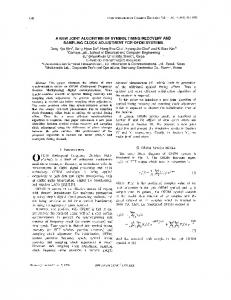
There are frequency offset, phase offset, symbol timing offset and sampling timing offset that constitutes synchronization errors of OFDM system. Among these, symbol timing offset, Td, and sampling timing offset, At(?+), are errors in the time domain, which are illustrated in Fig. 2. The time synch errors normalized by the nominal sampling period, T , can be represented by
Symbol timing recovery in the OFDM system is the function of detecting the symbol start position in the received sample sequences. After this step, demodulation can be carried out by removing the guard interval and input the useful data interval into FFT block. Symbol timing offset is the difference between the correct symbol start position and the estimated symbol start position. It is reflected in the individual phases of the complex value of each subcarriers. The relationship of the phase of the k-th subcarrier to the symbol timing offset Td is given by [6]
We can find that the value of the phase rotation 4k is proportional to subcarrier index k .
B. The Effect of Sampling Timing Offset Sampling clock adjustment is the function of maintaining the optimal sampling timing. To look into the effect of sampling timing offset easily, we may divide sampling timing offset into sampling phase offset and sampling frequency offset, because the effects are different from each other. First, the effect of sampling phase offset is similar to the effect of symbol timing offset. The relationship of the phase of the k-th subcarrier to the sampling phase offset At is given by
(7) We find that the value of the phase rotation $ k is proportional to subcarrier index k ; however, its effect is relatively less than that of symbol timing offset because the range of sampling phase offset spans f 0.5 of sample interval while the range of symbol timing offset is the multiple of sample intervals.
IEEE Transactions on Consumer Electronics, Vol. 44, No. 3, AUGUST 1998
1144
sampling clock adjustment using pilot carriers. First, the phase rotation occurred at the k-th subcarrier of the j-th OFDM symbol due to synch errors [ 5 ] is
+ 4o+ 2ndfT,, dk(A = 271% Td+dt(i) Tu
(9)
symbol timina offset
Fig 3 Phase rotation occurred at each subcarriers due to synch errors
The difference of the phase rotation between k= k, -th and k2-th subcarrier of the j-th symbol is expressed as in (lo), where k l , kz are assumed to be the pilot carrier indices which transmit the known complex signals between the transmitter and the receiver.
Second, the sampling timing is changed at every sample interval due to sampling frequency offset. In addition, the sample roblstuff phenomenon occurs periodically, so that it results in additional symbol timing offset, i.e., the receiver obtains (N+G-1) or (N+G+l) during One OFDM Of (N+G) samples. And due to sample rob/stuff phenomenon, additional phase rotation occurs at each subcarriers [4].
where Ak is frequency spacing between two pilot carriers, k1 and k z , i.e., dk=kZ-k1. We can notice from (10) that the difference of the phase rotation between the two pilots in a symbol is the function of the frequency spacing between pilots, ( kz - k , ) , the normalized symbol timing offset, T,/T,, and the normalized sampling timing offset, At(j ) / T,. Total time synch error, xi), is the sum of symbol timing where 6 is the number of sample rob or stuff, so offset and sampling clock offset; therefore, total time that its value is 1 or - 1. f, and Of, is sampling synch error can be obtained as (1 1). If a large number of pilots are used, we can use the average of frequency and sampling frequency offset, respectively. every phase difference as in (12). Since T d / T , is an integer and Ot(j) T, is a fraction, we can use the C. Phase Rotation Due to Synch Errors round-off function to divide the total time synch error Fig. 3 shows the phase rotation occurred between into an integer part and a fraction part as in (13) and arbitrary two consecutively received OFDM symbols Fig. 4. due to synch errors. We assume there is the symbol timing offset of 1 sample. The 1-st symbol includes the effects of symbol timing offset and phase offset as shown by line (1) and line (2). The magnitude of phase rotation due to symbol timing offset is proportional to subcarrier index, but phase offset shifts the constellation of FFT output by the same angle. In the 2-nd symbol, the effects of frequency offset and sampling timing offset are accumulated in the phase of previous symbol. The %i> = &%)I -r~^r(j)l) effect of frequency offset and sampling timing offset (13) are represented by line (3) and line (4), respectively. = ( integer part) ( fraction part) Thus, we have to estimate the symbol timing offset and sampling timing offset from line (2) or line (4), where 4-1 means the round-off function, and I&'which includes other synch errors. &j)]l L0.5. The value of the integer corresponds to the symbol timing offset and the value of the fraction can be used for correcting the sampling timing offset. IV. PROPOSEDALGORITHM Therefore, we can obtain the two time synch errors The algorithm proposed in this paper utilizes the simultaneously by using this algorithm, so that we can joint operation between symbol timing recovery and decrease the initialization tinie of the system.
+
+{Xi>
+
Kim et al.: A New Joint Algorithm of Symbol Timing Recovery and Sampling Clock Adjustment for OFDM Systems
+
symbol timing offset = 2 sample
\
---
1145
pa
-estimated tau -integer
plus ampling clock offset
x
symbol timing offset deusion area
k (camer index)
Fig. 4. Dividing time synch into symbol timing offset and sampling timing offset by using round-off function.
55 5
15
1
35
1
25
2
15
t
43
0
05
15
1
2
25
0
31, 4
15
5
l i m e sync error [sample]
06 04
g 02 9 C
g
-
"+ Fig. 5. Block diagram of the proposed algorithm.
o
2
gm 4 2
U
-04
Fig. 5 shows the block diagram of the proposed algorithm in which we can use the fraction as input of the phase detector of PLL (Phase Locked Loop) [71.
-0.6 I
- 5 5 -5 -45 -I -3s .J
4 5
.2
-1s
-1 -05
0
05
1
15
2
2.5
1 3s
,
I 4.5
5
l i m e sync ermr [sample]
(b)
Fig. 6. Estimation value vs. time synch errors (a) ? and integer part, and (b) Fraction part.
A. Character istic Curves
*
Fig. 6 (a) and (b) show the characteristic curves of 'data duration, i.e., 2 / N samples. Especially for the estimated symbol timing offset and the estimated reliable performance, the increase of the spacing sampling clock offset, respectively. From these figures, between the two pilots is desired, however, the we can find that symbol timing recovery and sampling estimation range is decreased. clock adjustment are able to operate independently each other. Fig. 7 (a) and (b) show the loop tracking of the C. Additional Mechanism f o r Symbol Timing Recovery proposed algorithm for input SNR of 5dE3, and It is necessary to estimate the symbol start at every normalized frequency offset of 0, 0.2. Initial symbol symbol and to verify whether the receiver keeps the timing offset, TJT,, is 10 samples, initial sampling correct symbol timing. However, when the channel is phase offset, dt(j)/T,, is -0.45 and initial sampling suddenly disrupted for a short time and some of the symbols are severly impaired, the symbol start frequency offset, A f J f , , is 10 ppm. estimated from those symbols may lead to unreliable behavior of the receiver. To avoid this, we need B. Estimation Range additional mechanism for reliable symbol timing The estimation range of the symbol timing recovery control. We modify the error detection method of ATM which uses pilot subcarriers to estimate symbol start is (Asynchronous Transfer Mode) cell header for this changed by the inter-pilot spacing Ak. purpose as illustrated in Fig. 8 [SI. If symbol timing recovery finishes, the value of estimated symbol start N T d < 2Ak becomes 0 and the stable mode is on. If the estimated value is not 0, the system mode changes The maximum r-mge is less than a half of the useful from the stable mode to the correction mode but the
*-
E E E Transactions on Consumer Electronics, Vol. 44, No. 3, AUGUST 1998
1146
T,(j)=T(j-l)&T(j-l)=T(i-Z) coAct symgo~timingd
Correction
Stable
TJj) != 0
Fig. 8. State diagram for symbol timing recovery control 0
5
1
0
1
5
x
i
2
5
3
0
3
5
4
0
4
5
5
0
Tlme [sample]
0
5
10
15
25
20
30
35
40
45
50
l i m e [sample]
(b)
Fig. 7. Tracking performance of proposed algorithm (SNR: 5dB) (a) Symbol timing recovery and (b) Sampling clock adjustment.
symbol timing is not compensated. In the correction mode, there are three states: state 1: if the estimated value of j-th symbol does not equal to that of (i- 1) -th symbol, the correction mode is kept and the symbol timing is not compensated. state 2: if the estimated value of j-th symbol equals to 0, the system mode changes from the correction mode to the stable mode, and the symbol timing is not compensated. state 3: if all estimated values of j , ( j - l ) , and ( j - 2 ) -th symbol are equal to each other, the system mode changes from the correction mode to the stable mode and the symbol timing is compensated. By using the control method explained above, it can deal with the sudden channel impairment.
V. SIMULATION RESULTS We apply the proposed algorithm to a model based on European DVB-T (Digital Video BroadcastingTerrestrial) standard [9] to evaluate the performance. DVB-T defines 2048 (2k mode) and 8192 (8k mode)
as the FFT size and 1/4, l/8, 1/16, 1/32 of the useful data interval as the length of guard interval. In addition, 142 scattered pilots among 2048 subcarriers are used, where the inter-pilot spacing is 12 times of inter-subcarrier spacing in a symbol. The OFDM model selected for simulation in this paper consists of 2048-point FFT, a guard interval of 256 samples, i.e., l/8 of the useh1 data interval, and 16-QAM modulation mapping scheme. We use the 2nd-order DPLL (Digital PLL) to adjust sampling clock, where the normalized loop bandwidth BLT is 0.005, 0.01, and 0.05, and the damping factor 6 is 0.7 171. The transmission channel is AWGN and multipath fading channel with LOS (Line-Of-Sight) and 20 multipaths [9]. Since the proposed algorithm may use the scattered pilots, the spacing between adjacent scattered pilots is 12 inter-subcarrier spacing, therefore, the maximum estimation range becomes k 8 5 samples. But, for reliable performance, we choose 60 inter-subcarrier spacing for the inter-pilot spacing d k in (1 1) and the estimation range becomes i:17. We use the symbol error rate, SER, and the probability that the symbol start estimation error is larger than n sample intervals, PEE( n), as the performance criterion of symbol timing recovery, and the steady state jitter for performance criterion of sampling clock adjustment. A. AWGN Channel
Fig. 9 shows PEE(n) in AWGN channel for input SNR of 0 and 5dB. Even at low SNR, symbol timing recovery of the proposed algorithm estimate the symbol start within 2 5 samples of the true symbol start. Fig. 10 shows SER vs. normalized frequency offset in AWGN channel for input SNR of 5, 15, and 25dB. We find that the proposed algorithms can be used for symbol timing recovery under normalized frequency offset of kO.3. Fig. 11 shows the steady state jitter vs. normalized frequency offset for input SNR of 5 , 15, and 25dB, and the normalized loop bandwidth ( B L T ) of 0.005, 0.01, and 0.05. We also find that the proposed
Kim et al.: A New Joint Algorithm of Symbol Timing Recovery and Sampling Clock Adjustment for OFDM Systems
-
1147
I.E+00
!I
1 E-01 c
8
5 E
1 E-02
9 n
e
1 E-03
w' n 1 E-04
0
1
3
2
5
4
6
8
7
9
10
1
0
2
3
n [sample)
~
_
_
_
~
7
6
8
9
10
~
-1
P
+SNRW~
Fig 9 PEE(n) vs. n
1.E-04
5
n [sample]
_
-B-SNRWB
4
N
R OdB + S N R
5dB + S N R
01
03
lode]
Fig. 12. PEE(n) vs. n.
1
I
0
0.2
01
0.3
0.4
1 E-04
0.5
I
I 0
Normalizedfrequency offset
05
___________
t 2 5 d B
t 5 d B +15dB
-25dB
Fig. 13. SER vs. normalized frequency offset (multipath fading channel).
Fig. 10. SER vs. normalized frequency offset (AWGN)
r-----l
04
Normalizedfrequency offset
__ t 5 d B -15dB
02
___-
lHW
,
-5dBOW5, --tM8001 t-548005 -0 -15480005 4- -15d8001 I
-
-moo1
--t m . 0 05
- -0
15dB,O"
- -x- - 15d8,OOl I - -c- 15dB,Offi
-a- -1568005
+25dBOO05' +.-25d8001
I
I +5dBOM)S
'"
1
- - ~ 25d8,O t 0051
--6-25dB 0 05
+-25dB.001
+25dB.O 05
- __ 0
01
02
03
04
I
Normalizedfrequency OLet
0
B. Multipath Channel
Fig. 12 shows PEE( a ) in multipath fading channel
0.2
0.3
0.4
Normalizedfrequenqofset
Fig. 11. Steady state jitter vs. normalized frequency offset (AWGN).
algorithms can be used for sampling clock adjustment under normalized frequency offset of -t 0.3.
0.1
Fig. 14. Steady state jitter vs. normalized frequency offset (multipath fading channel).
for input SNR of 0, 5, and 15dB. Symbol timing estimates the symbol start within + 4 samples of the true symbol start at SNR of 5dB. Fig. 13 shows SER vs. normalized frequency offset for
recovery
LEEE Transactions on Consumer Electronics, Vol. 44, No. 3, AUGUST 1998
1148
input SNR of 5, 15, and 25dB. Fig. 13 shows FEE at SNR 10dB. Fig. 14 shows the steady state jitter vs. normalized frequency offset for input SNR of 5, 15, and 25dB, and the normalized loop bandwidth of 0.005, 0.01, and 0.05. We find that the proposed algorithms can be used for sampling clock adjustment under normalized frequency offset of t0.2. (E)
VI. CONCLUSIONS In this paper, we discussed the effects of time synchronization errors on OFDM systems. Time synchronization errors are symbol timing offset and sampling timing offset, which have the characteristic that the degree of the phase rotation is proportional to subcarrier index. In general, because the symbol timing offset affects sampling clock adjustment, symbol timing recovery is carried out before sampling clock adjustment. The main problem with time synchronization errors is that until sampling clock adjustment, the sample robhtuff phenomenon due to the sampling clock frequency offset leads to adding the FFT window position offset. We proposed a new joint algorithm for symbol timing recovery and sampling clock adjustment using this characteristic. In addition, this algorithm can obtain two time synch errors simultaneously and can be implemented easily. The performance of the proposed algorithm is carried out by computer simulation under AWGN and multipath fading channels. We found that it works well at relatively low input SNR and under normalized frequency offset of t0.3. REFERENCES J. A. Bingham, "Multicarrier Modulation for Data Transmission: an Idea Whose Time Has Come," IEEE Commun. Mag., pp.5-14, May 1990. L. C. Cimini, Jr., "Analysis and Simulation of a Digital Mobile Channel Using Orthogonal FrequencyDivision Multiplexing," IEEE Trans. on Commun., Vol. COM-33, pp.665-675, July 1995. B. Le Floch, R. Halbert-Lassalle, D. Castelain, "Digital Sound Broadcasting to Mobile Receivers," IEEE Trans. on Consum. Electr., Vo1.35, pp.493-503, August 1989. Thierry Pollet, Paul Spruyt and Marc Moeneclaey, "The BER Performance of OFDM Systems using Non-Synchronized Sampling," Proc. of GLOBECOM, pp.253-257, 1994. Hiroshi Nogami and Toshio Nagashima, "A Frequency and Timing Period Acquisition Technique for OFDM Systems," Proc. of PIMRC, pp.1010-1015, 1995. S. U. Zaman, K. W. Yates, "Multitone Synchronization for Fading Channels," Proc. of ICC, pp.946-949, 1994. H. J. Choi, Synchronous Digital Communications, KyoHakSa, Korea? 1995.
181 Uyless Black, ATM: Foundation for Broadband Networks, Chapter 6, Prentice Hall, 1995. f91 ETSI, ETS 300 744 Digital Broadcasting Systems for Television, Sound and Data Service; Framing Structure, Channel Coding and Modulation for Digital Terrestrial Television, April 1996.
Kim et al.: A New Joint Algorithm of Symbol Timing RecoveIy and Sampling Clock Adjustment for OFDM Systems
BIOGRAPHIES Dong Kyu Kim was born on September 1969. He received the B.S.E.E. and M.S.E.E. degrees in Electronics Engineering from SungKyunKwan University, Suwon, Korea, in 1995 and 1997, respectively. He is currently working toward the Ph.D. degree in Electrical and Computer engineering at SungKyunKwan University, Suwon, Korea. His current research interests are communication systems engineering and digital modulationldemodulation with associated signal processing and synchronization.
Sang Hyun Do received the B.S.E.E. and M.S.E.E. degrees in Electronics Engineering from SungKyunKwan University, Suwon, Korea, in 1996 and 1998, respectively. He is currently working at LG Information & Communications Ltd., Seoul, Korea. His current research interests are communication systems engineering and digital modulatioddemodulation with associated signal processing and synchronization.
Hong Bae Cho received the B.S.E.E. degree in Electronics Engineering from SungKyunKwan University, Suwon, Korea, in 1997. He is currently working toward the M.S.E.E. degree in Electrical and Computer Engineering at SungKyunKwan University, Suwon, Korea. His current research interests are communication systems engineering and digital modulatioddemodulation with associated signal processing and synchronization.
Hyung-Jin Choi was born in Taegu, Korea in August 1952. He received the B.S.E.E. degree from the Seoul National University, Korea, in 1974, the M.S.E.E. degree from the Korea Advanced Institute of Science, Korea, in 1976, and the Ph.D. in degree Electrical Engineering (communications major) from the University of Southern California, Los Angeles, in 1982. From 1976 to 1979 he worked for the Central Research Lab. of the Gold Star Co., Seoul, Korea, as a research engineer. From 1983 to 1989, he worked for the Lincom Corp., Los Angeles, California. Since March 1989, he has been a faculty member with the School of Electrical and Computer Engineering, SungKyunKwan University, Korea
1149
and currently holds the rank of Professor. His main field of interests includes mobile radio engineering, satellite communications, communication systems engineering and digital modulatioddemodulation with associated signal processing and synchronization.
Ki Bum Kim was born on May. 2, 1962 in Ansung, Korea. He received the B.E. degree in Electronic Engineering from HanYang University, Seoul, Korea in 1985. Since 1985, he has been at Signal Processing Lab., Samsung Electronics Co., and has been engaged in the development of Advanced TV System and Ghost Cancellation System. His current research interests includes digital communication and digital HDTV channel coding.