sued by means of both data aided and decision directed solutions. ... This paper is based on âJoint Symbol Timing Recovery and Equal- ization for Short Burst ...
34
JOURNAL OF COMMUNICATIONS, VOL. 3, NO. 4, SEPTEMBER 2008
An Iterative Algorithm for Joint Symbol Timing Recovery and Equalization of Short Bursts Pietro Savazzi, Paolo Gamba, Lorenzo Favalli Department of Electronics, University of Pavia, Pavia, Italy Email: {pietro.savazzi, paolo.gamba, lorenzo.favalli}@unipv.it
Abstract— In this work a joint clock recovery (CR) and equalization scheme for short burst transmissions is presented. The joint optimization performance may be pursued by means of both data aided and decision directed solutions. The novel algorithm is based on an iterative scheme, exploiting a timing error function sampled at symbol rate. The symbol timing adjustment is implemented by an interpolation filter, built according to the Farrow structure. Equalization is obtained by baud spaced zero forcing (ZF) and minimum mean square error (MMSE) linear filtering. Performance is evaluated by simulating a QPSK transceiver and simulations results are compared with the ideal solutions, for both symbol timing recovery and channel equalization, under frequency selective multipath fading channel conditions. Index Terms— clock recovery, expectation maximization, MMSE, ZF, digital interpolation
I. I NTRODUCTION Modern and planned high speed telecommunications systems are based on the idea to share ”on demand” their capacity among users that are allowed to transmit chunks of data according to their needs. High speed receivers need precise timing to correctly understand the symbols and time sharing channel resources requires that tracking algorithms must be able to work on “packets” of data composed by a limited number of symbols. In digital communication receivers, frequency selective fading channel impairments may be counteracted by employing a linear baud spaced equalizer, under the assumption of a perfect symbol timing recovering. In order to mitigate the strong dependance on symbol timing errors, a fractionally spaced equalizer working at least at two samples per symbol can be used [1] [2]. Clock synchronization is usually accomplished through a feedback loop that control the phase of an analog local clock or by a feedforward circuit able to re-build a timing wave from the incoming received symbols [3]. The feedback loop may be controlled by a digital error, which tracks the received symbol timing and usually samples the incoming signal at twice the symbol rate [5]. An all digital implementation can be used if the samples at the output of an analog-to-digital converter (ADC) are not synchronized with the incoming This paper is based on “Joint Symbol Timing Recovery and Equalization for Short Burst Transmissions, by P. Savazzi, P. Gamba, and L. Favalli, which appeared in the Proceedings of the 66th IEEE Vehicular Technology Conference (VTC-2007 Fall), Baltimore, USA, Sept. 30 c 2007 IEEE. Oct. 3, 2007.
© 2008 ACADEMY PUBLISHER
analog signal. This may be realized by using a simple local oscillator (LO) instead of a voltage-controlled oscillator (VCO) to drive the ADC conversion. In this case, digital interpolation techniques may be employed in order to produce the correct sample values, at the modem output, that would occur if the original sampling had been synchronized to the incoming received symbols. In this sense the receiver had to compute the correct fractional delay needed to synchronize the incoming symbols, the interpolation filter coefficients and the regenerated sampling clock. The last action is generally not required if the data symbols ”are consumed at the receiver location” [3], like in burst communications. In [4], simulation results demonstrate that simple digital interpolations may gain the same performance of hybrid digitally controlled analog loops. Digital filter interpolation may be efficiently implemented in hardware by the Farrow structure, in which the only variable parameter is the fractional phase delay [6]. According to this, the re-computation of the filter coefficients are no longer needed. Farrow interpolation filters may be realized as allpass [7] or they can be included in the Nyquist receiver filter [8]. In this works, the main focusing is on open loop solutions, assuming that the synchronization process is done after the acquisition of the entire data-burst. In [9] a polynomial-based maximum-likelihood technique is presented for open loop synchronization in an all digital receiver which uses a Farrow interpolator, while in [10] a similar receiver structure is exploited for designing a very fast digital symbol timing recovery (STR) by using a second order interpolator, obtaining, as a unique drawback, a relatively poor performance due to the low filter order. Following this idea, a data aided STR scheme for burst receiver was presented in [11], based on a second order interpolator for fast estimating the correct receiver fractional delay while a higher 4th or 6th order filter is used for increasing the interpolation accuracy as well as the CR performance. A recent paper revealed that the joint design of both the interpolation filter and a decision feedback equalizer can improve the receiver performance [12], while in [13], it is presented an iterative algorithm for symbol timing recovery of short bursts working at the symbol rate. According to these premises, the basic ideas shown in this paper are to derive a new algorithm for joint STR and equalization of short data packets, in order to better exploit the information contained in the received burst sequence. The new STR burst-by-burst algorithm
JOURNAL OF COMMUNICATIONS, VOL. 3, NO. 4, SEPTEMBER 2008
is built starting form [13] using a timing error function found in [15], adapted to work in a burst receiver. In this sense the scope is to extend the results found in [12] to build an adaptive receiver in which information is iteratively exchanged between the STR interpolator and the equalizer, in a way similar to the one shown in [16]. The algorithm proposed in this paper, instead of attempting to directly estimate the channel delay and the equalizer coefficients, is based on the iterative refiltering of the received burst data. At each iteration the symbol timing phase and equalizer tap values move towards increasing values of likelihood, according to the generalized expectation maximization (EM) framework [17]. This work extends the results of [14] to the MMSE case. II. T HE
PROPOSED SCHEME
r(t) =
d(k)h(t − kT − τ T ) + w(t)
(1)
k=−∞
where d(k) are the transmitted symbols with timing period T , h(t) comprises the channel and all the transmitter and receiver filters and w(t) represents the AWGN (Additive White Gaussian Noise) contribution. Throughout the paper, QPSK will be assumed although the results can be easily extended to M-QAM modulations. The imperfect sampling time is taken into account by the unknown fractional delay parameter τ and the cascade transceiver filters are modeled as a raised cosine frequency response filter. The channel fading is considered to be frequency selective while time selectivity can be assumed to be negligible according to the short burst framework considered. After the analog to digital conversion, the signal is sampled at twice the symbol rate and can be represented by considering separately the two symbol halves: r(2n) =
P∞
k=−∞
r(2n + 1) =
P∞
d(k)h(k − 2n − τ /T ) + w(2n)
k=−∞
d(k)h(k − 2n − 1 − τ /T )+
+w(2n + 1) (2) where r(n) ≡ r(nT ). The first step of the algorithm is the choice of the half symbol sample closest to the right timing. This can be accomplished according to the maximum likelihood principle [1] [5] [9]: hP i N −1 ∗ L0 = ℜ n=0 r (2n)d(n) (3)
L1 = ℜ
hP N −1 n=0
i r∗ (2n + 1)d(n)
L0 and L1 represent the likelihood functions computed for the even and odd samples while d(n) are the preamble known symbol for the data aided (DA) case or the estimated ones at the receiver output for the decision directed © 2008 ACADEMY PUBLISHER
(DD) mode. N is the number of symbols considered in the computation, and may coincide with the burst length for the DD operation mode, while “*” represents the complex conjugate. Symbol rate samples for the subsequent steps are chosen depending on the maximum of the two computed likelihoods: x(n) = r(2n)
if L0 > L1 (4)
x(n) = r(2n + 1) if L1 > L0 A. Symbol timing recovery The samples provided by equations (4) are used to compute the fractional timing delay error by using what in [15] is called the ”type B timing error function”, in an adaptive burst-by-burst manner, following the same approach proposed in [13], [14]: f (τ ) = h(1)
The baseband received signal can be modeled as: ∞ X
35
(5)
where h(1) represents the first trailing echo of the channel impulse response which must be equal to zero in presence of perfect timing sampling. Equation (5) represents the starting point for deriving some linear timing error detectors to be used in analog and digital symbol timing recovery loops. In the work [13], only devoted to timing recovery, has been used the ”type A timing error function” of [15]. In this paper we have adopted the type B error function because it seems from simulation results that the joint equalization and STR performs better in this way. One important step of this work is to exploit the burst nature of modern digital modems, to directly implement the equation above and use it for computing the fractional delay correction to be used in a polynomial interpolator. This can be pursued by means of an iterative algorithm, for which the convergence is assured in the context of the generalized EM paradigm [17]. In this way the timing error computation is done in an adaptive manner at each received burst, using directly the channel impulse response estimation which takes into account the effects of ISI (Inter-Symbol Interference). Following this idea, a channel equalization step, based on the zero forcing (ZF) criteria [1] [5], is incorporated in the algorithm iterations in order to jointly perform both timing recovery and equalization. In order to avoid any matrix inversion, the channel impulse response may be computed by evaluating the cross-correlation: N −1 X ˆh(n) = 1 r(k)d∗ (k − n) N
(6)
k=0
where, as indicated in the equations above, the d(n) belong to the preamble or represent the estimated symbols for the DD operation mode [16]. After estimating the channel impulse response with the previous equation, the fractional delay of the channel, to be used for the polynomial interpolation, can be computed using (5): ˆ µ = τ /T ≃ ℜ(h(1))
(7)
36
JOURNAL OF COMMUNICATIONS, VOL. 3, NO. 4, SEPTEMBER 2008
as reported in [7], which satisfies the following condition: Vc = z
(11)
where: c = [C0 (z) C1 (z) · · · CL (z)]T (12) z = [1 z −1 · · · z −L ]T and V is the Vandermonde matrix: 0 0 01 · · · 10 11 · · · V= . .. .. .. . .
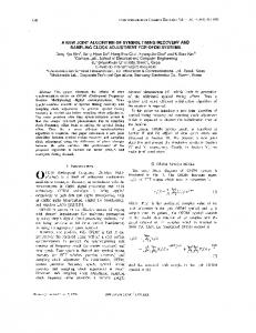
Figure 1. Farrow structure for the interpolation filter.
L0
where the real part is taken according to the facts that the generic complex envelope of the channel impulse response is complex while the used Nyquist shaping function is real [5]. In the next subsection we briefly review the Farrow structure for the digital interpolator which makes use of (7) for correcting the channel symbol timing delay. B. Digital filtering by Interpolation The Farrow structure (see Fig. 1) of the interpolation filter consists of L + 1 parallel FIR branch components with fixed coefficients having transfer functions Cl (z), for l = 0, 1, ..., L, and only one variable parameter µ. The parameter L is the degree of the polynomial while µ represents the fractional delay timing error correction. The impulse response of the interpolator in each sampling time interval Ts = T2 , where T is the symbol time, is: p(t) ≡ p(iT ) = p [(k + µ)Ts ] =
L X
cl (k)µl
(8)
l=0
The output of the Farrow scheme is: M/2−1
y(n) =
X
r(n − k)p [(k + µ)Ts ] =
L X
fl (n)µl
l=0
k=−M/2
(9) where: M/2−1
fl (n) =
X
r(n − k)cl (k);
(10)
k=−M/2
and M , the Farrow branch filter length, is equal to the filter order plus one. The basic idea of this structure is that the outputs y(i) form a polynomial approximation for the continuous-time signal r(t) at time instants iT = (n + µTs ). The obvious advantage, in terms of hardware implementation complexity, is that the filter coefficients are constant and the output time sampling is only controlled by the parameter µ. The design of Farrow interpolators can be done in several ways and traditionally it is based on Lagrange polynomials. In this work we consider the Farrow structure for the Lagrange interpolator polynomials, © 2008 ACADEMY PUBLISHER
L1
0L 1L · · · LL
(13)
The solution of (11) provides a filter structure in which the fractional delay µ ∈ [0, 1] and a constant phase delay with respect to the filter order. A more efficient construction is suggested in [7], with a new parameter range equal to [−0.5, 0.5]. This can be pursued by employing the matrix transformation T: � � n L n−m round( 2 ) for n ≥ m m Tn,m = 0 for n < m (14) where n, m = 0, 1, · · · , L and the new filter is obtained by replacing the solution of (11) with: c = TV−1 z
(15)
C. Generalized EM algorithm for joint STR and equalization The EM algorithm is a very general framework that provides an iterative procedure for computing maximum likelihood estimation (MLE) in situations where some parameters are missing. Let r be the random vector corresponding to the received signal samples. This is the incomplete set, while y = (r, µ, b) represents the complete data set; the receiver must choose the estimated symbol vector which maximizes: p(d|r) = p(d|r, µ, b)f (µ, b)
(16)
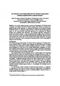
where the fractional timing delay µ and the equalizer coefficients b are the missing parameters and f (µ, b) is their joint probability density function. The EM algorithm proceeds iteratively by replacing the complete data likelihood function by its conditional expectation given r using the current estimate of (µ, b), called (µk , bk ). The maximization of (16) can be done by using the following two-step iterative procedure: 1) E-Step. Calculate Q(µ, b; µk , bk ) = E{p(d|r, µ, b)|rk , µk , bk } 2) M-Step. Choose (µk+1 , bk+1 ) that maximize Q(µ, b; µk , bk ), that is Q(µk+1 , bk+1 ; µk , bk ) ≥ Q(µ, b; µk , bk ). When a closed form solution of the M-Step computation does not exist, it is possible to use the generalized version of the algorithm for which the maximization over all
JOURNAL OF COMMUNICATIONS, VOL. 3, NO. 4, SEPTEMBER 2008
the possibile parameter values is replaced by [17, section 1.5.5, page 28]: Q(µk+1 , bk+1 ; µk , bk ) ≥ Q(µk , bk ; µk , bk )
(17)
That is choosing (µk+1 , bk+1 ) to increase the function over the parameter values (µk , bk ) instead of maximizing it over all the possible outcomes. In our scheme the E-Step corresponds to the interpolation of the matched filter output samples, using the Farrow structure described in (15), followed by the blockby-block equalizer. The M-Step is obtained in the generalized sense by using the type B timing error function, previously introduced and the equalizer coefficients recomputation. D. The complete procedure In fig. 2, the complete processing chain is shown while in the following each step of the iterative algorithm is explained in details. Please note that in the following equations superscript index represents the i-th received burst while subscript m is used for numbering the iterations; N is the burst length while Np is the preamble length or the number of samples used for computing the timing delay and the equalizer filter coefficients in the DD operation mode. In the latter case Np can be set ≤ N . Using the equations discussed in previous sections the detailed algorithm steps for the i-th burst are: 1) the half symbol closest to the right timing sampling is chosen according to (3) in the initialization step and it is kept fixed for all the i-th burst iterations; 2) According to the previous step the signal is downsampled to T and the DD symbols are estimated if needed by the DD mode operation: i xim (n) = rm (2n)
if L0 > L1 (18)
xim (n)
=
i rm (2n
(19)
where the function g(·) is the output of the M-QAM symbol detector; 3) the channel impulse response is estimated using the symbol preambles or the DD ones from (19) [16], for n = 0, 1, · · · , Np − 1: Np −1 X ˆ i (k) = 1 h xim (n)dim (k − n); m Np
(20)
k=0
4) the fractional delay parameter µim is computed, following the timing error function reported in [15] [5], by means of ˆ i (1)); µm ≃ ℜ(h (21) i
m
ˆ i is over5) the estimated channel impulse response h m sampled, by zeros insertion, and filtered by the Farrow branch filters cl , built according to (15): i ym (j) =
L X
M/2−1
X
l=0 k=−M/2
© 2008 ACADEMY PUBLISHER
where j = 2n; 6) The equalizer impulse response is obtained from the previous equation by the application of the zero forcing criterion: i i bim = (Ym (YH )im )−1 yDm
(23)
or the MMSE one: i i bim = (Ym (YH )im + σ 2 I)−1 yDm
(24)
where bim denotes the vector representation for the i equalizer impulse response, Ym is the convolution matrix of the channel impulse response provided i by (22), down-sampled to symbol rate, while yDm i denotes the dth column of Ym , representing the delay of the equalizer chosen in order to obtain a non-casual and symmetric impulse response. I~ is the identity matrix and σ is the noise variance which may be assumed known at the receiver or computed using the DD symbols of the previous iteration. In case of fractionally spaced equalization the rate of i ym (j) is left unchanged; i 7) The received signal rm (n) is filtered by bim (j), overs-ampled by two, where Ne denotes the equalizer filter length: i rm+1 (j) =
Le X
i rm (j − l)bim (j)
(25)
l=0
All the steps from 2) are repeated until convergence. The algorithm can be stopped when it reaches a maximum number of iterations or until NX e −1
|bim+1 (j) − bim (j)| < ǫEQU
(26)
j=0
+ 1) if L1 > L0
dˆim (n) = g[xim (n)]
37
ˆ him (j − k)cl (k)(µim )l , (22)
|µim | < ǫSTR
(27)
where ǫEQU,STR ≃ 0 represent the requested precisions, respectively for the estimated equalizer coefficients and the fractional timing error correction. Relation (27) is due to the fact that during iterations, the estimated fractional delay parameters go to zero as the received signal is refiltered by the interpolator. This is similar to the behavior of a clock recovery loop using the Mueller and M¨uller TED [15]. Down-sampling by two prior to filtering, in steps 5) and 7) can be easily and jointly obtained by means of a polyphase implementation [18]. III. P ERFORMANCE E VALUATION Performance of the new scheme has been evaluated by simulating a QPSK transceiver with raised cosine pulse shaping, affected by frequency selective multipath fading and additive white Gaussian noise. Multipath fading is modeled as a two rays channel with impulse response equal to h = [1 0.5]. The estimated channel impulse response has three tap coefficients while the equalizer
38
JOURNAL OF COMMUNICATIONS, VOL. 3, NO. 4, SEPTEMBER 2008
Figure 2. The proposed scheme
length is set to nine. The order of the interpolation filter is four and it has been obtained by (15). The rolloff factor of the shaping filter is α = 0.35. For the MMSE case, the noise variance is iteratively computed using the DD symbols of the previous iteration.
0.3 DD, N = 256 p
DA, N = 64 p
0.25
0.2
0.15
A. Convergence analysis Fig. 3 shows the convergence speed for the fractional timing correction µim . The length of the transmitted bursts is N = 256 while Np denotes the number of symbols used for the channel impulse response and delay computations. It represents the known preamble length in the DA case or the number of DD symbols used for estimating the unknown parameters during iterations. The channel timing error is set to τ = 0.25T representing the worst case for the clock recovery problem. In the DD case all the burst symbols are used for computation while a preamble length of 64 seems to be a good tradeoff between performance and bandwidth efficiency. Regarding the timing error correction capability, a number of iterations greater than 5-6 seems to be enough. Fig. 4 and 5 show the convergence speed of the equalizer coefficients, computed by (23). As the timing correction goes to zero, the equalizer tap values go to a Dirac unit pulse. This is due to the iterative re-filtering of the signal as explained in the previous section. Obtained results show that a number of iteration greater than 5-6 is sufficient from the point of view of linear ZF equalization purposes. Simulation conditions and parameters are the same of those in Fig. 3. © 2008 ACADEMY PUBLISHER
|µi | m
0.1
0.05
0
−0.05 1
2
3
4
6 5 Number of iterations
7
8
9
10
Figure 3. |µim | versus number of iterations, burst length N = 256.
B. SER performance SER curves have been obtained in the same channel conditions assumed in the previous section, considering the worst case, corresponding to a channel delay τ = 0.25T and the channel estimator operating in the decision directed mode. The iterative algorithm stops when it reaches a maximum number of iterations equal to 10. Simulation results of the new scheme are compared with those obtained assuming ideal clock recovery and zero forcing/MMSE equalization, under an ideal channel impulse response acquisition, considering the same equal-
JOURNAL OF COMMUNICATIONS, VOL. 3, NO. 4, SEPTEMBER 2008
39
0
1.5
10 |b(0)| |b(1)| |b(2)| |b(3)| |b(4)| |b(5)| |b(6)| |b(7)| |b(8)|
1
ZF−STR ideal N=256 N=128 N=512 −1
10
−2
10 |bi | m
SER
0.5
−3
10
0 −4
10
−0.5
−5
1
2
3
4
6 5 Number of iterations m
7
8
10
9
10
7
8
9
11
10
12
13
14
E /N (dB) b
Figure 4. Equalizer coefficients |bim (j)| versus number of iterations, DA case, Np = 64, burst length N = 256.
0
Figure 6. SER versus Eb /N0 , DD case, Np = N = 128, 256, 512.
−1
10
MMSE−STR ideal N=256 N=128 N=512
1.5 |b(0)| |b(1)| |b(2)| |b(3)| |b(4)| |b(5)| |b(6)| |b(7)| |b(8)|
1
−2
10
SER −3
10 |bi | m
0.5
−4
10
0
−5
10
−0.5
7
8
9
11
10
12
13
14
E /N (dB) 1
2
3
4
6 5 Number of iterations m
7
8
9
10
b
0
Figure 7. SER versus Eb /N0 , DD case, Np = N = 128, 256, 512. Figure 5. Equalizer coefficients |bim (j)| versus number of iterations, DD case, Np = 256, burst length N = 256.
izer filter length. In DD mode, all the transmitted burst symbols have been used for channel impulse response and delay computations (Np = N ). IV. C ONCLUSION This work introduces a novel burst-by-burst joint symbol timing recovery and linear equalization scheme, which makes use of an adaptive computation of the timing error function, by exploiting the impulse response channel estimate in an iterative manner. The timing error function output is used directly as fractional delay parameter of an all-pass Farrow polynomial interpolator while the linear equalizer coefficients are computed using the same estimated channel impulse response by the application of the ZF and MMSE criteria. The scheme convergence is assured by the generalized framework of the expectation maximization algorithm [17]. The MMSE performance is better than the ZF one, with only a little increase © 2008 ACADEMY PUBLISHER
in computational complexity due to the noise variance computation. Presented results look promising, especially from the point of view of using this solution jointly with a more sophisticated symbol estimation technique, like decision feedback equalization (DFE) [12], decoding scheme or a combination of both [19]. R EFERENCES [1] J. G. Proakis, Digital communications, 3rd ed. New York: McGraw-Hill, 1998. [2] D. J. Artman, S. Chari, R. P. Gooch, “Joint equalization and timing recovery in a fractionally spaced equalizer”,in Proc. IEEE 26th Asilomar Conf. Sugnals, Systems and Computers, Oct. 1992, pp. 25-29. [3] F. M. Gardner, “Interpolation in digital modems-Part 1: Fundamentals, ”IEEE Trans. Communications, vol. 41, no. 3, March 1993. [4] L. Erup, F. M. Gardner, R.A. Harris, “Interpolation in digital modems-Part 2: Implementation and performance,” IEEE Trans. Communications, vol. 41, no. 6, June 1993. [5] H. Meyr, M. Moeneclaey, S. A. Fechtel, Digital communication receivers, John Wiley & Sons, 1998.
40
[6] C.W. Farrow, “A continuously variable digital delay element,” inProc. IEEE International Symposium on Circuits and Systems (ISCAS’88), Espoo, Finland, pp. 2641-2645, June 7-9, 1988. [7] V. V¨alim¨aki, “A new filter implementation strategy for Lagrange interpolation,” in Proc. IEEE International Symposium on Circuits and Systems (ISCAS’95), Seattle, Washington, USA, pp. 361-364, April 30 - May 3, 1995. [8] J. Vesma, “A frequency-domain approach to polynomialbased interpolation and the Farrow structure,” IEEE Trans. Circuits and Systems II, vol. 47, no. 3, pp. 206-209, March 2000. [9] R. Hamila, J. Vesma and M. Renfors, “Polynomial-based maximum-likelihood technique for synchronization in digital receivers,” IEEE Trans. on Circuit and Systems II Analog and Digital Signal Processing, vol. 49, no. 8, pp. 567-576, August 2002. [10] N.D. Vo, T. Le-Ngoc, “Fast symbol timing recovery techniques for flexible PAM and QAM modems,” in Proc. IEEE Canadian Conference on Electrical and Computer Engineering (CCECE 2003), Montreal, Canada, pp. 19591962,May 4-7, 2003. [11] P. Savazzi, P. Gamba, S. Callegari, “An all-digital clock recovery architecture for the BRAN hiperaccess uplink receiver,” in Proc. IEEE Vehicular Technology Conference (VTC Spring 2006), Melbourne, Australia, pp., May 7-10, 2006. [12] M-H. Cheng, T-S. Kao, “Joint design of interpolation filters and decision feedback equalizers,” IEEE Trans. on Communications, vol. 53, no. 6, pp. 914-918, June 2005. [13] P. Savazzi, P. Gamba, “Iterative Symbol Timing Recovery for Short Burst Transmission Schemes,” accepted for publication on IEEE Trans. on Communications. [14] P. Savazzi, P. Gamba, L. Favalli, “Joint Symbol Timing Recovery and Equalization for Short Burst Transmissions,” in Proc. IEEE Vehicular Technology Conference (VTC fall 2007), Baltimore, MD, USA, September 30 October 3. [15] K.H. Mueller, M. M¨uller, “Timing recovery in digital synchronous data receivers,” IEEE Trans. Commun., vol. 24, pp. 516-531, May 1976. [16] R.R Lopes, J.R. Barry, “Blind Iterative Channel Identification and Equalization,” in Proc. IEEE International Conference on Communications (ICC 2001), Atlanta, GA, USA, pp. 2256-2260, June 11-14, 2001. [17] G.J. McLachlan, T. Krishnan, The EM algorithm and extensions, Wiley Interscience, 1997. [18] J.G. Proakis, D.G. Manolakis, Digital signal processing, 3rd ed. Upper Saddle River, New Jersey: Prentice Hall, 1996. [19] J.R. Barry, A. Kavˇci´c, S.W. McLaughlin, A. Nayak, and W. Zang, “Iterative timing recovery,” IEEE Signal Processing Magazine, vol. 21, no. 1, pp. 89-102, January 2004. [20] T. Zhao, A. Nehorai, B. Porat, “K-means clustering-based data detection and symbol-timing recovery for burts-mode optical receiver,” IEEE Trans. Commun., vol. 54, no. 8, pp. 1492-1501, August 2006. [21] J.M. Cioffi, G.P. Dudevoir, M.V. Eyuboglu, G.D. Forney, “MMSE decision-feedback equalizers and coding-part I: equalization results,” IEEE Trans. Commun., vol. 43, no. 10, pp. 2582-2594, October 1995. [22] J.M. Cioffi, G.P. Dudevoir, M.V. Eyuboglu, G.D. Forney, “MMSE decision-feedback equalizers and coding-part II: coding results,” IEEE Trans. Commun., vol. 43, no. 10, pp. 2595-2604, October 1995. [23] P. Savazzi, L. Favalli, E. Costamagna, “Design of digital receiver filters for reconfigurable wireless terminals based on Interpolation,” in Proc. WPMC 2005, AAlborg, Denmark, September 18-22, 2005.
© 2008 ACADEMY PUBLISHER
JOURNAL OF COMMUNICATIONS, VOL. 3, NO. 4, SEPTEMBER 2008
Pietro Savazzi received the Laurea degree in Electronics Engineering from the University of Pavia in 1995. In 1999 he obtained the Ph.D. in Electronics and Computer Science from the same University and then he joined the Ericsson Lab Italy, in Milan, as a system designer, working on broadband microwave systems. In 2001 he moved to the Marconi Mobile, Genoa, Italy, as a system designer in the field of 3G wireless systems. Since 2003 he has been working at the University of Pavia as a telecom researcher and there he is currently teaching, as a contract professor, three courses on digital signal processing and wireless systems. His main research interests are in digital receiver techniques for wireless systems and magnetic RW channels.
Paolo Gamba is currently Associate Professor of Telecommunications at the University of Pavia, Italy. He received the Laurea degree in Electronic Engineering cum laude from the University of Pavia, Italy, in 1989. He received also from the same University the Ph.D. degree in Electronic Engineering in 1993. From 1992 to 1994 he was a R&D engineer in the Microwave Laboratory of Siemens Telecomunicazioni, Cassina de Pecchi, Milano, Italy. In 1994 he joined the Department of Electronics of the University of Pavia first as a Teaching Assistant, then as Assistant and now Associate Professor. Since 1997 he has been teaching Radiocommunications Systems, Electrical Communications, and Remote Sensing Image Processing. Dr. Gamba is a Senior Member of IEEE, Associate Editor of IEEE Geoscience and Remote Sensing Letters and currently the Chair of the Data Fusion Committee of the IEEE Geoscience and Remote Sensing Society. His current research interests include remote sensing data fusion for urban applications, especially SAR urban analysis, satellite image interpretation for civil protection purposes, digital signal processing for wireless communications, sensor networks.
Lorenzo Favalli is an Associate Professor of Telecommunications at the University of Pavia. He graduated in Electronic Engineering form Politechnic of Milano in march 1987 and received the PhD degree from the same University in 1991. In 1987 he was the recipient of the ”Oglietti” prize from AEI-CSELT for the best thesis work on communication and switching. In 1988 received the special prize at the international contest ”Computer in the Cathedral” sponsored by NCR and International Cathedral Association developing a multimedia hypertext system for the fruition of cultural heritage. During 1990 he has been a visiting scientist at Washington University in St. Louis (USA) with a AEI-ISS grant. Since 1991 he is with the Department of Electronics of the University of Pavia initially as an Assistant Professor and now as Associate Professor. In these years he has been teaching courses on Telecommunications Systems, Digital Communications and Multimedia Transmission. Current research interests involve signal processing for wireless communications and video coding, cooperative transmission techniques over wireless and p2p networks.