A New Method for Calibrating Depth and Color Camera Pair Based on Kinect Weihua Liu Yangyu Fan Zhang Zhong Tao Lei School of Electronic and Information Engineering, Northwestern Polytechnical University
[email protected]
Abstract
mension of the calibration objects, the approach of calibration are involved in three categories: 3D reference object based, 2D plane based, self-calibration. In view of the number of the camera, calibration can be divided by adopting multi-cameras or just single one. A standard approach for calibrating independent camera adopting the 2D plane model which could ignore the depth information in world coordinate and make the model freely moved. The Kinect can be view as multi-camera, which can detect the depth information region from 0.4m to 4m , hence, we take advantage of this information to make a calibration and obtain the corresponding points instantaneously. In previous work, Daniel Herrera [1] gives a whole process of Kinect calibration in his paper, their method is based on raw depth image which the disparity value need to be calibrated. In our method for calibrating the color camera, we improve Zhang′ s method [2] and adopt a new cross shape to calculate the intrinsic and extrinsic matrix. The advantage of this shape is that we can choose eight point out of the main square area which do not participate in calibration , and reproject them to visualize the error between idea value and estimate value. As for the depth camera, to read depth information directly from the depth image make calibration process much easier and faster. In consideration of this advantage and the disadvantage of fuzzy boundary and the overlapping of image, we adopt 1D object for depth camera calibration with under knowing the depth value of specific pixel.
In this paper, we present a method that can calibrates color camera and depth camera of Kinect simultaneously, and finally get the relative pose between them. The calibration process for color camera and depth camera is designed by taking advantage of two different method respectively. As we know, the depth information can be acquired readily from the depth image, however, under the consideration of the fuzzy boundary and the overlapping of object in depth image, we choose using one-dimensional object for calibrating depth camera and propose a nonlinear method to optimize its intrinsic parameter. As for color camera calibration, we design a cross shape object for calibration and validation. Both methods are strongly robust to noise and much easier to implement. The experiment result shows a better accuracy in comparison with the proprietary calibration procedure of the manufacturer.
1. Motivations Camera calibration, specifically for obtaining the relationship between depth and color information, is an very important step before many applications ranging from scene reconstruction to object tracking and recognition. In order to track the trace of human hand precisely from Kinect camera, the pixel position of the hand in both images should be matched perfectly. Hence, A well corresponding relationships is desired for the depth and color camera pair. Therefor, this matching process include internal calibration of each camera as well as external calibration of relative pose between two camera.
3. The Basic Theory of the Perspective Camera Model 3..1 Mapping Relationship
2. Introduction
The pinhole model is the well know model for calculating the camera intrinsic and extrinsic parameters. Let us denote a 2D point as: m = [u, v]T and a 3D point as: M = [X, Y, Z]T . In order to simplify the camera pro-
There exist many methods to measure the camera intrinsic matrix and extrinsic matrix. According to the di-
c 978-1-4673-0174-9/12/$31.00 ⃝2012 IEEE
212
ICALIP2012
jection modeled as matrix multiplication, homogeneous coordinates are bring in by adding 1 as the last element for both 2D point and 3D point: m ˜ = [u, v, 1]T and T ˜ M = [X, Y, Z, 1] . Hence, the relationship between the world coordinate point M and its image coordinate point m is given by: ˜ sm ˜ = A[R, t]M (1) where s is the an arbitrary scale factor. A is called camera intrinsic matrix given by: α γ u0 A = 0 β v0 (2) 0 0 1
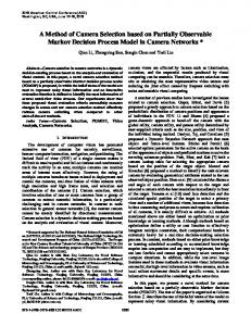
(a) planer model
with α and β define scale factor in image u and v axes; u0 and v0 are principal points which transfer image center from (0, 0) to (u0 , v0 ); [R, t] is camera extrinsic matrix with size 3 by 4. The 3 by 3 matrix R and 3 by 1 column t relate to rotation and translation transformation from world coordinate to camera coordinate separately. Typically, we joint matrix A,[R, t] together which called camera matrix: C = A[R, t] (3) Without loss of generality, we set camera coordinate equal to word coordinate, therefore, R = I and t = 0. Equation (1) can be rewritten as follow: Zm ˜ = AM
(b) stick model Figure 1. The object model of calibration
(4)
the arbitrary scale s is substituted by the Z-component of point M . The reprojection from pixel image to camera coordinate can be write as follow: ZA−1 m ˜ =M
3..3 Camera Matrix based on General Perspective Camera Model
(5) In our cross shape plane model, we first consider the camera matrix C which always has the form of :
3..2 Calibration Method When refers to the color camera calibration, generally, a planar checkerboard will be introduced. Because it can be readily constructed from any available planar surface. The corners on the checkerboard can provide suitable constraints for color image. In order to get a better performance, here we make a cross shape checkerboard not only provide constrain for color image, but also take advantage of eight corners from four protruding bar to make error visualization. As for depth camera, it is impossible to extracting each corner from checkerboard. Hence,we using 1D object (e.g.a stick) with one end fixed to calibrate the depth image. Constraints condition can be achieved by freely moving another end of the stick during calibration process. At least six image are required to satisfy the constraints with this stick model calibration and also do a better performance.
c11 C = c21 c31
c12 c21 c31
c13 c21 c31
c14 c21 = A[r1 , r2 , r3 , t] (6) 1
r1 , r2 , r3 is the column of R. To determination matrix C, at least six points pair are required (11 equations) between image and world coordinate. Therefore more than six points pair need to be extracted to provide robustness for calibration. Actually, we extract pixel points from the main square of cross shape checkerboard. Here Harris corner detection is introduced to automatically extract the corner which on each intersection of grid. It shows in Fig.1(1). Finally, matrix C is solved by using the least-square solution on a set of linear equations( [4]).
213
4. Color Camera Matrix based on the 2D Plane
5..1 Establishing 1D Object Model Equation Suppose a series of images with stick object are captured by depth camera. As shown in Fig.1(2), in world coordinate, the stick are marked by three collinear points O, C, B denoted by o, c, b in pixel coordinate respectively. Point O is fixed in space, point B is another end of stick,and stick OB move around O. The position of the point C can be computed with respect to O and B as follow: C = λO O + λB B (11)
Without lose the generality, the 2D model plane can be assumed on Z = 0 of the world coordinate system. Hence, the whole pinhole model can be simplify as: u [ ] X v = A r1 r2 t Y (7) 1 1 In the above equations, the world points [X, Y, 1]T and its image point m ˜ is related by the homography matrix H: [ ] H = A r1 r2 t
where λO and λB is known to decide the position of C. According to reprojection relation in (5), O, B, C in equation(11) can be written as: ZC c˜ = ZB λB ˜b + ZO λO o˜
We denote the 3 by 3 matrix H by: [ ] H = h1 h2 h3
where ZO , ZB , ZC is the depth value of points O,B,C; o˜, ˜b, c˜ is the homography vector of o, b, c. By performing cross product with c˜ on both sides of the equation (12), we have:
The matrix H is equal to the matrix C without its third column because of Z = 0 of world coordinate, we determine intrinsic matrix A by establishing constraints be[ ] tween H and A r1 r2 t as follow: [ ] [ ] h1 h2 h3 = λA r1 r2 t (8)
ZB = −ZO ρ2 where ρ2 =
λO (˜ oט c)(˜ bט c) λB (˜ bט c)(˜ bט c)
ZC = ZO ρ3 = 0 = hT2 A−T A−1 h2
˜
(14)
˜
o×b)(˜ c×b) where ρ3 = λO(˜c(˜ ט b)(˜ cט b) From above equation, each depth value of mark points O,B,C can be acquired by knowing the depth value of fix points and the relative pixel position.
(9) (10)
Above two equations provide two constraints, in order to get additional constraints, we need more checkerboard image to input. Normally five or more images are taken to increase robustness. In our experiments, we providing ten different images with different angles and positions. Finally , A can be obtained from A−T A−1 by applying Cholesky factorization [4] and the intrinsic and extrinsic parameters can be obtained by using close-form solution method which is described in detail in [2].
5.
(13)
By performing cross produce with ˜b on both sides of the equation (12), we have:
where λ is an arbitrary scalar. Using the knowledge that r1 and r2 are orthonormal column [2], we have: hT1 A−T A−1 h2 hT1 A−T A−1 h1
(12)
5..2 Linear Parameter Estimation The length OC from middle point C to fixed point O is known to be λB L: ∥C − O∥ = λB L
(15)
Substitute O, C by using reprojection equation (5), we obtain: ∥A−1 ˜ − ZO o˜)∥ = λB L (16) d (ZC c
Calibration based on 1D Object for Depth Camera
where Ad is the intrinsic matrix of depth camera with 3 by 3 size. Substitute ZC by equation(13) and (14), we can get:
As for depth camera calibration, to avoid the occlusion problem and reduce the quantity of corner selection. We choose a stick(1D object) by observing three collinear points on them and add a condition that the stick should rotates around a fixed point [3] as shown in Fig.2.
ZO ∥A−1 d P ∥ = λB L where P =
214
λO c˜(˜ o × ˜b)(˜ c × ˜b) − o˜ (˜ c × ˜b)(˜ c × ˜b)
(17)
Square the equation (17), we obtain: 2 T ZO P KP = λ2B L2
Note that equation (19) and (20) are both nonlinear minimization problem, here the Levenberg-Marquardt Algorithm can be implemented to solve this equation. Both of the functions requires initial guess: the initial guess of Ac , R, t for color camera and initial guess of x1 , · · ·, x6 for depth camera. We have already obtain all these parameter in section 5.2.
(18)
−1 where K = A−T d Ad . Because the equations (18) contains 5 unknown intrinsic parameters in matrix Ad and 1 unknown of depth value ZO . To solve this equation, at least n(n ≥ 6) observations should be obtain to obey the basic constraints. After rewrite (18) into a set of linear equation and solve it by taking advantage of Closed-Form Solution in [3], we can uniquely extract five intrinsic parameters and the depth ZO , ZB , ZC .
7. Relate Position Estimation 7..1 Initial Guess of Relate Position In order to match corresponding pixel points, the salient translation and a slightly rotation between two camera should be consider. We denote that Mci and Mdi i ∈ 1, 2, · · ·, n are ith points pair of color and depth camera coordinate respectively. After calibrating both intrinsic parameter, Mci and Mdi can be written as :
6. Nonlinear Optimization After acquire both of the intrinsic matrix from color and depth camera respectively. we need to refine it by minimizing the weighted sum of squares of the measurement reprojection errors. By minimizing the following functional, we can obtained the maximum likelihood estimate: ∑ min ∥M − ϕ(Ac , R, t, m)∥2 (19) min
∑
kinect ∥ZM − ρi ZO (x1 , x2 , · · ·, x6 )∥2
(21)
ZA−1 c mci = Mci
(22)
where Z is the depth value of Mdi ; The relationship between Mci and Mdi as follow:
(20)
In equation (19), the error for the color camera is the Euclidean distance between measured point M in world coordinate and its project position ϕ(Ac , R, t, m), where Ac is the color intrinsic matrix, R, t is the transformation matrix from word to camera coordinate. In equation (20), the error evaluation is between Kinect depth Zkinect and Z-component of its reprojected point. kinect ZM , (M ∈ O, Bi , Ci ) is the depth value product by kinect. ρi ZO (x1 , x2 , · · ·, x6 ), i ∈ 1, 2, 3 corresponding to the estimate depth value ZO , ZB , ZC in each depth image; here, ρi is the coefficients relate to pixel position of o,c,b in depth image. Typically, ρ2 = 1, ρ2 and ρ3 come from equation (13) and (14). To get the value of x1 , x2 , · · ·, x6 need to solve Close-Form Solution( [8]) which composed by α β γ u0 v0 and ZO as follow: 2 x1 = ZO /α2 2 x2 = −ZO γ/α2 β 2 x3 = (ZO /β 2 )(1 + α2 /β 2 ) 2 x4 = ZO (v0 γ − u0 β)/α2 β, 2 x5 = ZO ((−γ(v0 γ − u0 β)/α2 β 2 ) − v0 /β 2 ) 2 x6 = ZO (((v0 γ − u0 β)2 /α2 β 2 ) + (v02 /β 2 ) + 1)
Mci = KMdi + tk
(23)
Where K is 3 by 3; tk is 3 by 1; We can write equation (23) as homogeneous form: ˜ ci = Th M ˜ di M
(24)
˜ ci and M ˜ di is the homogeneous matrix of Mci where M and Mdi ; Th is the combination of [K, tk ] with 4 by 4 size; The matrix Th can be divide into three column of Th = [T1 , T2 , T3 ]T , each Ti = [ri1 , ri2 , ri3 , ti1 ]T i ∈ 1, 2, 3 ˜ ci and can be solved by knowing at least four pair of M ˜ Mdi . A set of points in depth camera coordinate are concatenated in matrices of the homogeneous form: ˜ d = [M ˜ d1 , M ˜ d2 , · · ·M ˜ di , · · ·M ˜ dn ]T M ˜ di = [Xdi , Ydi , Zdi , 1]T where M For color camera : Mc = [Xc , Yc , Zc ]T where Xc = [Xc1 , Xc2 , · · ·, Xci , · · ·, Xcn ]T . From the corresponding points pair in camera coordinate, we have:
ZO is the estimate depth value of fix point composed by x1 , x2 , · · ·, x6 : ZO = (x6 − [x24 +
ZA−1 d mdi = Mdi
Xc Yc
(x2 x4 − x1 x5 )2 ]/x1 ) (x1 x3 − x22 )
Zc
215
˜ d T1 = M ˜ d T2 = M ˜ d T3 = M
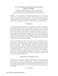
The results of table 3 shows the relate points position from depth camera coordinate to color camera coordinate. From above table 3, we obviously know that the rotation of two camera is very smaller compare to big displacement in x and y axis due to the structure of the Kinect. In our experiments, we extract 10 points pair from 10 images each to implement the relative pose estimation. Fig.2(1) shows the reprojection error of color image, we can see that the result is much better after implement nonlinear optimization and both average error involve in a lower error range after roughly around 120 points count. Fig.2(2) shows the stick error in depth camera, we can see that both Close Form solution and nonlinear optimization error are less than 5mm and the error become steady after around 40 points count.
A valid rotation and translation result can be get through using SV D decomposition : Ti = U V T where U SV T is the SV D of MdT . Finally, the matching matrix Q is composed by A˜c , A˜d , [R, t] which can be written as: Q = A˜c [K, tk ]A˜−1 d
(25)
For each points in the depth image, the corresponding points in color image can be matched by using above matching matrix Q.
7..2 Relate Position Optimization To refine the combination matrix Th , we can minimize the weighted sum of squares of the reprojection error between the ideal corner point and reprojection corner point both from color camera coordinate. The resulting cost function is: ∑ ˜ di )∥)2 min (∥Mmeasure − φ(Th , M (26)
Table 1. The intrinsic parameter of the color camera
˜ di ) = Where Mmeasure is ideal corner point. φ(T˜h , M ˜ Mci . Note that (26) is nonlinear system. The LevenbergMarquardt algorithm can also be used to minimize (26) the rotation and translation parameters in the combination matrix Th . To initialize the function, a rough guess of the matrix Th are computed from section 7.1.
α 531.7796
β 531.2455
γ 3.1110
u0 314.2244
v0 267.6517
Table 2. The intrinsic parameter of the depth camera
8. Experiment Result with Real Images
α 626.0642
To show the validity of our method for matching the corresponding point pair from depth image to color image, we first do two calibration experiment for color camera and depth camera separately. We test both camera with an off-the-shelf Kinect device which the color camera and depth camera arranged horizontally. For color camera calibration, 30 image are generated for calibration and 10 image for validation. The result of intrinsic parameters shows in table 1. For depth camera calibration, we use a 445 mm long stick with three markers . Fifty images are sampled from the video stream by Kinect. To avoid the singularity of calibration [3], it means no six observation points should on the same quadratic curve. For this purpose, we use the spherical coordinates to define the direction of the 1D object, set the radial distance as the length of the stick, and divide the polar angle φ ∈ [0, 90◦ ] into 12 angle degree level. For each angle degree level, we take five depth image as constraint requirements. 50 image are generated for calibration and 50 image for validation. This calibration results of the intrinsic parameters are shown in Table 2.
β 589.3261
γ 3.0999
u0 320.7359
v0 234.9799
Table 3. The relate points position between color and depth camera coordinate R Rx Ry Rz
216
1.0563 0.0029 1.1239e-9
-0.0122 0.9610 2.4309e-9
0.0322 0.1052 1.0000
9. Conclusions Table 4. The Relate points position between color and depth camera coordinate
In this paper, we present a calibration algorithm for a depth and color camera pair that is strong enough to get corresponding points instantly.Our method is based on the Kinect SDK, the depth data is automatically converted into millimeters, hence, the depth information can be directly read by us other than need to consider the disparity calibration. For calibrating the intrinsic parameter in depth camera, we use one-dimensional objects instead of the planner object to freely extract mark point and propose a new nonlinear method based on the maximum likelihood criterion between the estimate depth value and the measured depth value. The result shows our method has high accuracy level with any color and depth image pair from Kinect.
t tx
-9.4511
ty
-133.0640
tz
4.5059e-5
4 Error after Nonlinear Optimization Error under Close−Form Solution
The Average Reprojection Error (pixel)
3.5 3 2.5
References 2
[1] Herrera C, Daniel and Kannala, Juho and Heikkila,Janne. Accurate and Practical Calibration of a Depth and Color Camera Pair, 14th International Conference on Computer Analysis of Images and Patterns, 2011, pp.437-445. [2] Zhang,Z. A flexible new technique for camera calibration, IEEE Transactions Pattern Analysis and Machine Intelligence, Nov 2000, pp.1330 - 1334. [3] Zhengyou Zhang.Camera calibration with onedimensional objects,IEEE Transactions Pattern Analysis and Machine Intelligence, July 2004, pp.892 - 899. [4] J.Heikkila and O.Silven,A Four-step Camera Calibration Procedure with Implicit Image Correction,in CVPR, 1997, pp.1106. [5] J.J. More, The Levenberg-Marquardt Algorithm, Implementation and Theory,Numerical Analysis, G.A. Watson,1977. [6] Heikkila, J and Silven, O,A four-step camera calibration procedure with implicit image correction,CVPR 97, 1997, pp.1106-1112. [7] S.Fuchs and G.Hirzinger,Extrinsic and depth calibration of tof-cameras,CVPR, 2008, pp.1-6. [8] Z. Zhang,Camera Calibration with One-Dimensional Objects,Proc. European Conf. Computer Vision, May 2002, pp.161-174. [9] Zhao, Zi-jian and Liu, Yun-cai,New multi-camera calibration algorithm based on 1D objects,Journal of Zhejiang University SCIENCE A, 2008, pp.799-806. [10] Faugeras.O, Three-Dimensional Computer Vision: A Geometric Viewpoint.,MIT Press, 1993.
1.5 1 0.5 0
0
20
40
60 80 100 120 The number of the corner count
140
160
(1) Corner reprojection error in color camera 35 Length error after Nonlinear Optimization Length error with Close Form Solution
The average stick length error (mm)
30
25
20
15
10
5
0
0
10
20 30 The Number Of the Image Count
40
50
(2) Depth error between Kinect measure and estimated measure after nonlinear optimization Figure 2. The object model of calibration
217