1. A new precise ultrasonic range sensor based on the emission of two coded FSK signals combined to a ping-pong strategy. Vincent PIERLOT, Pierre TASSIN ...
1
A new precise ultrasonic range sensor based on the emission of two coded FSK signals combined to a ping-pong strategy Vincent P IERLOT, Pierre TASSIN and Marc VAN D ROOGENBROECK {vpierlot, m.vandroogenbroeck}@ulg.ac.be INTELSIG, Laboratory for Signal and Image Exploitation Montefiore Institute, University of Liège, Belgium
Abstract—Ultrasonic range sensors are widely used in robotic applications mainly for obstacle avoidance or environment map generation. They are attractive because of the low cost of transducers, associated electronics and for ease of implementation. However, they have several limitations related to propagation physics. Most of these systems send a short pulse at an ultrasonic frequency; this pulse is reflected on any object in the environment and then returns to the sensor. If one knows the constant speed of sound in the air, the distance between the emitter and the object is derived from the propagation time. The main drawbacks originate from multiple propagation paths, echoes, diffraction effects, etc, resulting in ambiguous or unreliable range measurements. This paper presents a new ultrasonic range sensor using a ping-pong strategy with a beacon, FSK modulation, and coded signals to overcome these main limitations. Index Terms—ultrasonic sensor, microcontroller, mobile robot, robot sensing system.
R1 (master) d α H
R2 (beacon)
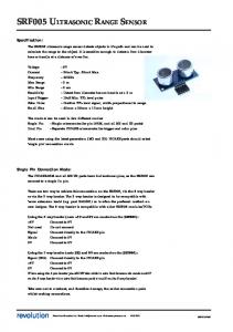
Figure 1. Upper view of the E UROBOT playing field with the two robots R1 and R2 . The purpose of our platform is to get unambiguous and reliable range measurements d from our robot R1 to the opponent robot R2 . This range measurement is to be combined with the angular position α (from our robot heading H) given by the system described in [8] to compute the full position of the opponent robot.
I. I NTRODUCTION Ultrasonic range sensors are widely used in robotic applications mainly for obstacle avoidance [1], [2], mapping and localization [3], and absolute positioning via range measurements and trilateration [4]. They are attractive thanks to the wide availability of low cost transducers, ease of implementation, low power consumption and low weight, and simple associated electronic circuitry. However they have some limitations [5]: interferences from multiple paths propagation, echoes or crosstalk when using several sensors [6], [7] tend to produce ambiguous or unreliable range measurements. They are also characterized by a low range resolution due to the duration of the emitted burst and a poor angular resolution due to their large beamwidth (all the objects located in this beam generate an echo). In our work we address the avoidance problem between two autonomous mobile robots evolving in the same area during the E UROBOT contest (Fig. 1). The purpose of our platform is to get unambiguous and reliable range measurements from our robot to the other one (opponent robot). This range measurement is to be combined with the angular position given by the system described in [8] to compute the full position of the opponent robot. The advantage against simplest proximity sensors is that we can use this position in real time to generate more efficient trajectories.
A. Overview This paper presents a new ultrasonic range sensor using FSK signals and a ping-pong strategy to get unambiguous and reliable range measurements between two mobile robots, without the need of a synchronization channel (as in [4]). Our system was primarily developed for the E UROBOT contest but can be used in any other mobile robot application. The paper is organized as follow: first we briefly present the E UROBOT contest, and Section III details the complete hardware platform. Then, in Section IV, we describe the software architecture and the range measurement principle. Experimental results and physical characteristics of our platform are given in Section V. Section VI concludes the paper. B. The E UROBOT contest The E UROBOT contest opposes two autonomous mobile robots moving on a 2.1 × 3 [m2 ] large playing field. Despite that rules change every year, the goal remains the same: each robot must pick up objects and place them in containers or defined areas of the playing field. The winner is the robot that accumulates the largest number of points in 90 [s]. In this contest the opponent robot avoidance problem is recurrent and critical for three main reasons: 1) the avoidance
- 36 -
2
R1 R2
D
E1
D
E2
D
E3
A1 A1
R3
A1
R4
A1
Band Pass Filter
E1 R4
R1 E2
E4 R3
R2
A2 Schmitt Trigger
E3
µC D
E4
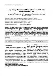
Figure 2. Bloc-diagram of the emitting and receiving part of the master or beacon. Ei are the ultrasonic emitters, D are the MAX232 drivers, and µC is the common microcontroller. Ri are the ultrasonic receivers, A1 are the pre-amplifiers and A2 is the second amplifier.
system has to be approved prior to competition, 2) we have to be fair play during the match (no collision with the opponent robot), and 3) we have to reach our goal efficiently considering that another robot moves inside the same area. Furthermore it is allowed to place a beacon onto the opponent robot to help the avoidance problem. We choose to use this particularity to obtain reliable range measurements between the two robots (Fig. 1). II. T HE RANGE MEASUREMENT PROCESS The range measurement is based on ultrasonic transducers because of their advantages (low cost, ease of implementation). These transducers are used in combination with other mechanisms to cope with some common limitations. In particular, we have the opportunity to use a ping-pong strategy since we can place a beacon onto the opponent robot. The complete system is composed of a master card located on our robot and a beacon located onto the opponent robot. As explained below, it has the advantage to keep the propagation path under control: 1) we are sure that the signal is reflected at the beacon and 2) we are sure that the signal is sent by that beacon. The purpose is to get unambiguous and reliable range measurements between the master and the beacon. Here the term “unambiguous” means that we want to measure the distance between our robot and a specific point, regardless of all the obstacles. The reliable property means that we want to be sure that the signal travels back from our beacon and that it is not affected by noise or other ultrasonic signals. These goals can be achieved by using a ping-pong strategy between the master and the beacon and by using coded signals as follows: the master sends a digitally coded signal C1 in all directions (ping). This signal is received and decoded by the beacon. If the decoded signal corresponds to C1 , the beacon answers with a digitally coded signal C2 in all directions (pong). Finally, the master receives and identifies this code C2 and measures the ping-pong time-of-flight to derive the range. After the completion of a cycle, the master restarts a measuring cycle with a new ping (deadlocks are avoided thanks to a timeout counter). A first particularity of this system is the absence of synchronization between the master and beacon
local times. A second particularity is the possibility to compute the range at the beacon side, allowing other applications of our system. III. H ARDWARE DESCRIPTION The complete system is composed of two sub-parts: the master card located on our robot and the beacon (Fig. 6) put onto the opponent robot. Fundamentally the two parts contains exactly the same hardware except for some details like the form factor, the power part (small battery for the beacon), and the I²C communication with other cards for the master. Since the communication is bidirectional, the master and the beacon contain each an emitting and receiving part, which are identical. For that reason we will not describe the master and the beacon hardware but the emitting and receiving parts. A unique PIC microcontroller is used to control both parts. A. The emitting part The emitting part (Fig. 2) is composed of four ultrasonic emitters (PROWAVE 328ST160) working at the frequency fc = 32.8 [kHz] and driven each by a MAX232 chip. These chips are used as voltage converters to drive the emitters with a higher voltage than the card power supply (5 [V]). The microcontroller directly drives the MAX232 chips together with two opposite logical signals to get about 20 [V] differential voltage between the driver outputs. This solution (inspired from the D EVANTECH SRF08 ultrasonic range finder) is a simple and low cost method that permits to reach the required emitting power for our application. The four emitters are placed in a square pattern (see Fig. 6 for an illustration) to emit in all directions, the total beam angle of each emitter being about 100 [degree]. B. The receiving part The receiving part (Fig. 2) is composed of the four associated ultrasonic receivers (PROWAVE 328SR160), the preamplifiers, an adder, a band-pass filter, a second amplifier, and finally a Schmitt trigger. The four receivers outputs are amplified individually, then added together. This resulting
- 37 -
3
Figure 3. Rising time of an ultrasonic emitter/receiver pair for a step at the central frequency fc = 32.8 [kHz]. The rising time is about tr = 150 [µs].
signal is band-pass filtered, re-amplified, and finally reshaped by a Schmitt trigger to get a clean 0-5 [V] square wave at the input of the microcontroller capture module. The receivers are placed the same way as for the emitters to receive signals from all directions. The four signals could be analysed independently but it would have required a more complicated analog circuitry and a more complex software. Moreover the signal resulting from the addition of the four signals suffices because only one or two receivers will give a significant contribution. Note that we could have used a metal cone above the transducers as in [4] to emit or receive in all directions but this idea was abandoned because of construction constraints. IV. S OFTWARE DESCRIPTION A. The communication channel As explained in section II, the whole system is based on a communication channel between the master and the beacon. Our simple hardware allows us to use an On-Off keying amplitude modulation. Despite being simple, this solution fails because of the excessive rising and falling times of the transducers (see Fig. 4 and 3). As a result, this modulation scheme would require to use very long bit durations, resulting in very long codes and a low acquisition rate. We decided to use a Frequency Shift Keying (FSK) modulation for several reasons: 1) it is simple to generate a square wave of a precise frequency with a microcontroller, 2) rising and falling times are not a concern, 3) FSK is resilient to channel noise and 4) is less sensitive to multipaths. Whereas the emitters (and receivers) have a band-pass characteristic, it is possible to drive them with a frequency close to the central frequency (fc = 32.8 [kHz]), even at the cost of a small loss for the emitted power. We choose the two following frequencies for our FSK modulation: f0 = 32.05 [kHz] and f1 = 33.33 [kHz]. This choice results from a tradeoff between the desired bitrate, the acceptable power loss, and the Doppler effect affecting the received frequencies when the robots move.
Figure 4. Falling time of an ultrasonic emitter/receiver pair after a 6 [ms] burst at the central frequency fc = 32.8 [kHz]. The receiver continues to oscillate for a long time after the pulse has stopped. The falling time is about tf = 50 [ms].
B. The decoding process The output of the receiving circuitry is connected to a capture module of the microcontroller. This capture module is configured to capture the local time (free running counter) on every rising edge of the input signal. The absolute difference between two consecutive captures gives the instantaneous period of the FSK signal. These periods are filtered by a simple running mean filter (5 values). This filtered output is used to decide whenever we are receiving the low frequency f0 or high frequency f1 of the FSK modulation, the decision threshold being simply the mean of these two frequencies. At this time we have a binary information of the FSK signal. This information is filtered by a sliding median filter (5 values) to remove the glitches due to noise. The duration of a bit has been fixed to 32 periods of the signal (the bitrate is about 1000 [bit/s]). At each transition of the binary information, an algorithm counts the identical consecutive values and transform this number N to the corresponding number k of underlying bits. In theory, we would have N = 32k but the glitches around the transitions tend to produce a number N which is not a multiple of 32. The integer k is then chosen such that: N ∈ [32k − 16, 32k + 16[
k≥1
The binary data are then reconstructed after each signal frequency transition and are constantly compared to C1 (at the beacon) or C2 (at the master). When a match occurs, the beacon and the master resend their codes and the cycle restarts in a loop. C. The ping-pong codes In our application, we only need two different codes (Fig. 5). To increase robustness, these codes must satisfy some properties: • The codes must be as different as possible (to minimize the probability to identify C1 as C2 or C2 as C1 ). Since
- 38 -
4
Dummy bits Master → Beacon (C1 )
0 1 1 1 0 1 0 0 1 0
Beacon → Master (C2 )
0 1 0 0 1 0 1 1 0 1
Figure 5. Codes used for the communication between the master and the beacon (C1 ) and between the beacon and the master (C2 ). The first and last bits surrounding the codes are the dummy bits.
there are only two codes, we choose C2 whose parts are the binary complement of parts of C1 . • If two identical codes are received consecutively, one must identify these two codes only twice in a sliding window (due to the decoding and identification algorithm). The length of a code has been fixed to 8 bits, resulting from a compromise between the robustness and the acquisition rate. As explained in section IV-B, the whole decoding process is based on the transitions in the binary information. For that reason, we have added two dummy bits around the codes. These dummy bits are respectively the complement of the first and last bits of the codes to create the necessary transitions. There were many codes obeying the previous properties and the choice was somewhat arbitrary. V. E XPERIMENTAL RESULTS AND CHARACTERISTICS Our system has been used successfully during the E UROBOT contest in June 2010. The acquisition rate, which depends on the distance, reaches about 22 [Hz] at 50 [cm] and decreases to 10 [Hz] at 10 [m]. We measured an accuracy of 5 [mm] and a standard deviation of 8 [mm] at 2 [m]. The system never failed and no false measure was returned by the master. The transmission error rate for the codes is below 3 % in normal conditions. It doesn’t mean that a measure could be wrong but that the measure is discarded if an error is detected on C1 or C2 after the decoding process. Table I summarizes the main characteristics of our system. Table I C HARACTERISTICS OF OUR ULTRASONIC RANGE SENSOR . acquisition rate accuracy standard deviation master/beacon consumption central frequency FSK high frequency FSK low frequency embedded software
22 [Hz] @ 50 [cm] and 10 [Hz] @ 10 [m] 5 [mm] 8 [mm] @ 2 [m] 50 [mA] 32.8 [kHz] 33.33 [kHz] 32.05 [kHz] about 2000 [ASM instr.]
VI. C ONCLUSION We have presented a new ultrasonic range sensor used during the 2010 E UROBOT contest to address the avoidance problem between a robot and its opponent. The system is composed of a master card on a robot and an active beacon (Fig. 6) put onto the opponent robot. The system uses a ping-pong strategy in conjunction with coded signals and FSK modulation to achieve unambiguous and reliable range measurements.
Figure 6. Picture of the ultrasonic beacon onto the opponent robot. One can see the ultrasonic transducers arranged in four pairs of emitters and receivers at the upper side. Below are the IR emitting diodes of the system described in [8].
The use of this ping-pong strategy in conjunction with the coded signals provides several benefits. The most important is the possibility to identify the ultrasonic signals based on their codes; indeed, the go and return codes between the robots differ. This results in unambiguous and reliable range measurements. Another benefit is the absence of synchronization between the master and the beacon since the ping-pong timeof-flight is computed solely based on the master local time (the processing time at the beacon is known and taken into account in the calculus). Resilience to noise on the channel and multipaths is obtained via a FSK modulation of the signal. R EFERENCES [1] J. Klahold, J. Rautenberg, and U. Rückert, “Ultrasonic sensor for mobile mini-robots using pseudo-random codes,” in International Heinz Nixdorf Symposium: Autonomous Minirobots for Research and Edutainment, vol. 97, October 2001, pp. 225–232. [2] S. Shoval and J. Borenstein, “Using coded signals to benefit from ultrasonic sensor crosstalk in mobile robot obstacle avoidance,” in IEEE International Conference on Robotics and Automation (ICRA), vol. 3, July 2001, pp. 2879–2884. [3] A. Burguera, Y. González, and G. Oliver, “Sonar sensor models and their application to mobile robot localization,” Sensors, vol. 9, no. 12, pp. 10 217–10 243, December 2009. [4] J. D. Bjerknes, W. Liu, A. Winfield, and C. Melhuish, “Low cost ultrasonic positioning system for mobile robots,” in Towards Autonomous Robotic Systems (TAROS), Aberystwyth, United Kingdom, September 2007, pp. 107–114. [5] K.-W. Jörg and M. Berg, “Sophisticated mobile robot sonar sensing with pseudo-random codes,” Robotics and Autonomous Systems, vol. 25, no. 3-4, pp. 241–251, November 1998. [6] J. Borenstein and Y. Koren, “Error eliminating rapid ultrasonic firing for mobile robot obstacle avoidance,” IEEE Transactions on Robotics and Automation, vol. 11, no. 1, pp. 132–138, February 1995. [7] Q.-H. Meng, S.-Y. Lan, Z.-J. Yao, and G.-W. Li, “Real-time noncrosstalk sonar system by short optimized pulse position modulation sequences,” IEEE Transactions on Instrumentation and Measurement, vol. 58, no. 10, pp. 3442–3449, October 2009. [8] V. Pierlot and M. Van Droogenbroeck, “A simple and low cost angle measurement system for mobile robot positioning,” in 20th Annual Workshop on Circuits, Systems and Signal Processing (ProRISC), Veldhoven, The Netherlands, November 2009, pp. 251–254.
- 39 -