cascaded connection of input switched and H-bridge converters, which can provide 2N+l voltage levels for each phase. The proposed SVPWM strategy treats ...
The 2014 International Power Electronics Conference
A New SVPWM Strategy for Input Switched Multilevel Converter
Li Xiong,U. R. Prasanna,Akin Bilal,Kaushik Rajashekara Power Electronics and Drives Laboratory http://www.utdallas.edu/pedll The University of Texas at Dallas,Richardson,TX,75080 Email: {li.xiong,prasanna.ur,bilal.akin,k.raja}@utdallas.edu Abstract- This paper proposes a new space vector pulse width modulation
( SVPWM)
has not been presented and the computation is intensive due to the rotating d-q plane. .. In this paper, a new SVPWM control strategy for an input switched multilevel converter topology,which treats the multilevel converter as a two-level converter, is proposed to modulate the output voltages, allowing simple implementation. The proposed technique relies on introducing an offset vector close to the reference vector, shifting the origin to this offset vector,and operating in a two-level hexagon sector. A simple yet effective algorithm is proposed to generate the offset vector with minimum amount of computation. The procedure of synthesizing the reference voltage vector is a simple three-step process: a) locating the offset vector, b) determining switching pattern, and c) calculating dwelling time of each nearest vector (NV). The proposed SVPWM technique is analyzed on a seven level input switched converter configuration. With the proposed SVPWM strategy, the switching frequency of the input switched converter can be significantly decreased, and the H-bridge can be switched at close to line frequency.
strategy for a hybrid input
switched multilevel converter. The converter topology is a cascaded
connection
of
input
switched
and
H-bridge
converters, which can provide 2N+l voltage levels for each
phase. The proposed SVPWM strategy treats the multilevel converter as a two-level converter by introducing an offset vector. With generated switching pattern, it is possible to obtain minimum number of switching-state transitions and switch
the H-bridge
close
to
line
frequency;
thus,
the
switching losses can be significantly reduced. The proposed SVPWM
strategy
has
been
realized
on
a
seven-level
converter to demonstrate the principle of operation. The advantages of the proposed scheme and architecture are verified by both simulation and experimental results.
I INTRODUCTION The multilevel converter topologies in general can generate high-quality voltage waveforms where power semiconductor switches are operated at a very low frequency [I]. Due to the low switching frequency, the power can be efficiently transferred with better power quality and low electromagnetic interference (EMI) noise. Additionally, multilevel converters feature several dc links, allowing independent voltage control and MPP tracking in each string. There are three traditional multilevel converter topologies; the diode clamped (DCC),flying capacitor clamped (FCC),and cascaded H bridge (CHB) converters. Among them, the three-level DCC converter is widely accepted in industries for different applications. However, it has several disadvantages at higher voltage levels such as higher cost due to more number of power devices, deviation in dc link capacitor voltage and so on. These issues are also valid for flying capacitor based multilevel converters. Though cascade H-bridge converters do not have dc link capacitor voltage drifting issue, multiple isolated DC sources, which are usually provided by phase shifted transformers,are needed. The phase shifted transformers are bulky and expensive, which impairs the power density and cost-effectiveness of the converters. To address the issues associated with the traditional multilevel converters mentioned above, a number of multilevel converters with hybrid configurations such as input switched converters,are proposed in [2]-[5].
This paper is organized as follows. In section II, operating principles and switching states of the hybrid input switched multilevel converter, are introduced. The new SVPWM strategy is described in Section III. The simulation and experimental results are provided in Section IV to illustrate the effectiveness of the proposed SVPWM strategy. Finally, the conclusions derived from the study are presented in section V. II POWER CIRCUIT OPERATION PRINCIPLES The seven-level input switched multilevel converter consists of two stages as shown in Fig. I. The first stage consists of three power arms, which are named as input switched power converter in the rest . this paper. Each power arm includes two devices in back-to-back configuration. The dc linl
/
/
'\
I/...................f......\".".-/-............. � +O.5T1"" O.5T
--1- --1---1 --1-- 1- --1 -- r- --
'\
..........\:.
r----
- -
1 - - T - - 1- --1 -- 1 -T ---1----
·6 OL---CO.OLOS O.-"-O,S C---CO-'-. OC-, ----c -C -O. --' OCC2----:0. � OCC2S O.L03-C-O.OL3S :--CC C-� O.04 Time(s)
_Ts_
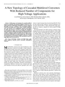
(b) Fig. 9 (a) Simulation results of three phase phase currents when modulation index 0.8; (b)Simulation results of phase currents when modulation index 0.5
Fig. 6. Duty cycle generation of switching vectors; (a) Using two phase shifted triangle carriers, (b) Using a single triangle carrier.
=
IV SIMULATION AND EXPERIMENTAL RESULTS
=
I
The simulation and experiments are conducted to verify the effectiveness and viability of the seven-level input switched converter modulated with the proposed SVPWM strategy. The parameters used In the simulations are listed in Table III.
I
I
I
I
I
I
I
� 0
-0.6 Alpha
(a)
l- - � - -I ____ 1 1- _ -!- _ ---J -0.6
-0.4
-0.2
0 Alpha
0.2
0.4
0.6
(b)
Fig. 10 (a) Simulation results of three phase currents in polar plane when modulation index 0.8; (b) Simulation results of three phase =
233
The 2014 International Power Electronics Conference
currents in polar plane when modulation index
4():)
�':m �200
__
1 - - - t- - - --t ---1----
--
-1 --1--1- --1---I I I ----------I I I II. 4[«(llU Freq...oency(Hz)
0.5
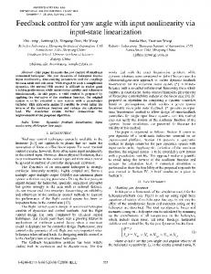
more voltage levels are available when the modulation index is higher, which provides lower voltage THD and better power quality. To support this, the frequency spectrum analysis of the line voltages for both cases is shown in Fig. II. The line voltage THD is 12.56% when modulation index is 0.8, while the THD is 18.29% when the modulation index is 0.5. The harmonics around the switching frequency,S kHz, can be observed from the figure. The relationship of the voltage THD and the modulation index for the given switching frequency of 5 kHz is plotted in Fig. 12(a). As it can be seen,the voltage THO decreases as the modulation index increases. It is worth mentioning that inverters usually operate with high modulation index to maximize the utilization of dc link capacitors. The relationship of voltage THD and switching frequency for the given modulation index of 0.5, is shown in Fig. l2(b). From the figure, it can be seen that the voltage THD does not significantly decrease as switching frequency reaches to a specific level. This relationship provides insightful information and guidance on the determination of switching frequency, addressing the trade-off between voltage THO and power loss. The experimental results are presented in Fig. 13 to Fig. IS. As seen from the results, the experimental results are consistent with the simulation results.
I I I I -- 1---1 -- 1---1 --
1 -- -.!- - - � ---1----
° C�
=
� ___ L __ � ___ L __ I I j j I --- I -- j --- I --
� ___ L __ � ___ L __ I I I I -- 1---1 -- 1---1 --
__
�l'-'-'
Fig. 11 (a) Frequency spectrum analysis of line voltages when modulation index 0.8, THO 12.56%; (b) Frequency spectrum analysis of line voltages when modulation index 0.5, THO 18.29% =
r
[
;
I -- I --- , -
r
t
=
=
I I
I , --, ---I -----
I I
I I .
I __ I
1
I __ I
,
- , ---
�'t.