Interleaved SVPWM and DPWM for Dual ThreePhase Inverter-PMSM: An Automotive Application *Subhadeep Bhattacharya, Student Member, IEEE, Diego Mascarella, Member, IEEE, and Geza Joos, Fellow, IEEE McGill University *email:
[email protected]
Abstract- This paper studies the dual three-phase inverter configuration for an electric vehicle drive feeding a dual threephase permanent magnet synchronous machine. Employing interleaved SVPWM and DPWM modulation techniques with the proposed configuration, the input capacitor ripple current has been substantially reduced to 50-60 % compared to that of a conventional 2-level VSI. The optimal interleaving angles have been identified for capacitor ripple reduction considering both modulation indexes and power factors pertaining to the traction motor’s operating range. The dual three-phase inverter’s switching losses have been analyzed for two different DC-link voltages and output power levels and a 15-20% reduction in switching loss has been noted.
I.
INTRODUCTION
High-power, battery-interfaced traction drives employing conventional two-level inverters have three regions for improvement. Referring to Fig.1, these regions include 1) the input dc-link ripple current, 2) the inverter switching and conduction loss and 3) traction motor current waveform quality. In region I, the inverter generates high frequency at its input dc bus [1, 2] due to ripple current currents device switching. Switching frequencies in an EV drive typically range between 4-20 kHz leading to input ripple currents of approximately 30-60% of the rated load current [3,4]. In order to avoid significant degredation of the battery, the dc-link capacitor’s function is to handle the highfrequency ripple currents such that the battery ripple current is limited to an appropriate threshold. It should be noted that large quantities of high-frequency ripple content handled by the dc-link result in capacitor losses associated with its equivalent series resistance (ESR) [1,3-5]. At high operating temperatures, 50°-120° C, typical of an automotive system, the capacitor ripple current capability is greatly reduced. This requires the traction drive to use an oversized capacitor, thus increasing the cost and weight of the traction drive [6]. Several papers in the literature have analyzed the ripple content of the dc-link capacitor current and recommended modifications to modulation schemes such that it can be reduced. In [1, 2], analytical expressions for the capacitor RMS ripple current have been discussed for different modulation indexes and power factors. Use of the highfrequency film capacitor [4], corresponding losses and selfheating of the capacitors for different PWM techniques have been analyzed in [6]. In [8], the influence of the capacitor’s ESR at different switching frequencies, modulation indexes
978-1-4799-2262-8/14/$31.00 ©2014 IEEE
I
II III
Fig. 1. Conventional 2-level VSI and motor
and power factors have been analyzed and a modified space vector modulation (SVPWM) algorithm has been proposed in [9] to reduce the loss in the DC-link capacitors. These studies used the conventional 2-level VSI and a 3-phase PM motor. Recent studies on the dual three-phase inverter-PMSM [3] have used interleaved sine-PWM (SPWM), with 1800 phase shifted carrier waveforms, to reduce the capacitor ripple current for different modulation indexes and motor speeds. Returning to Fig. 1, the two remaining regions for improvement of the motor-drive system deal with 1) the inverter conduction and switching losses and 2) the traction motor current waveform quality and associated losses. The battery-interfaced EV drive, operating at a high switching frequencies (5-20 kHz) and supplying high power (60-100 kW), incurs high inverter switching and conduction loss. Different modulation schemes have been proposed in [13] which employ discontinuous pulse-width modulation (DPWM) to reduce the switching loss. Finally PMSM stator loss, torque ripple and permanent magnet heating are also important factors in the design of the traction drive [7]. Several authors have discussed the effects of using a dual 3phase PMSM [7, 10, 11, and 12] on torque ripple and stator losses. The dual 3-phase PMSM has two separate three-phase stator winding sets with a phase-difference between them. It has been shown that the 300 phase shifted dual PMSM produces lower torque ripple and higher stator loss. Whereas, 1800 phase shifted dual PMSM produces higher torque ripple but a nearly decoupled two 3-φ motor system. The main aim of this study is to use the dual 3-φ inverterPMSM, with two sets of stator windings, 1800 phase shifted as shown in Fig. 2 and to analyze the effects of interleaved SVPWM and DPWM switching schemes. The investigation has been divided into three different parts. First, the influence
iinv2
iinvtot ibat
iinv1
ia2
icap
ia1
a1 Vbat
Cdc‐link
a2
b1
b2
c1
ic1 c2
ib2
ib1 ic2
Fig. 2. Dual 2-level inverter feeding a dual 3-phase PMSM (180° phase-shifted stator winding sets)
II.
INPUT CAPACITOR RIPPLE ANALYSIS
O/p currents(A)
600
B. Harmonic Contents of Capacitor Ripple Current: Single Inverter-PMSM & Dual Inverter-PMSM Referring to Fig. 2, in the dual-inverter PMSM configuration, each inverter supplies power to dedicated sets of three-phase stator windings, while using a common DC bus. Compared to the single inverter-PMSM topology, the dual inverter-PMSM’s input capacitor’s current harmonic components are due to both inverters. This is illustrated in
ibat & iinv (A)
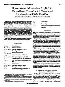
A. Single Inverter-PMSM Current Waveforms The classical 3-phase inverter has an input current which can be decomposed to a dc component and ( and its several harmonic components, at and around is the operating integer multiples (n ) [3], where switching frequency of the system. The harmonic components present in the inverter’s input current are handled by the dc capacitor whereas the dc component of the input current is supplied by the battery. In Fig. 3, the inverter’s output 3, battery phase currents, dc-link capacitor current current and inverter input current have been plotted for the drive configuration shown in Fig. 1. The simulations have been conducted using a passive load with the same power as a single PMSM (100 kVA) supplied from a 400 V DC battery with a 500 μF dc-link capacitor. The modulation index (m) and power factor (pf) are 0.5 and 0.9, respectively. The modulation index has been calculated with reference to the maximum dc-link voltage using SVPWM. Referring to Fig. 3, the capacitor RMS ripple current is 168 A and the battery current varies considerably.
ia ib ic
400 200 0 -200
-400 0.02 0.0205 0.021 0.0215 0.022 0.0225 0.023 0.0235 0.024 0.0245 0.025 simulation time (s) icap & icapRMS(A)
of using the aforementioned PWM techniques on the harmonic contents of the capacitor current ripple have been analyzed for different operating points. Secondly, based on the analysis, suitable interleaving angles have been identified for different operating points. Finally, the inverter switching and conduction losses have been quantified for different operating points, considering two different system specifications: 1) Vbat: 400 V, maximum power: 100 kVA and 2) Vbat: 700 V, maximum power: 200 kVA.
500
0
icapRMS
icap -500 0.02 0.0205 0.021 0.0215 0.022 0.0225 0.023 0.0235 0.024 0.0245 0.025 simulation time (s) ibat
400
iinv 200 0 0.02 0.0205 0.021 0.0215 0.022 0.0225 0.023 0.0235 0.024 0.0245 0.025 simulation time (s)
Fig. 3. Single 3-phase inverter-PMSM o/p currents, capacitor ripple currents (RMS value: 168 A), battery current & inverter input current
In2
β=0 In2 In1 (i)
nβ In1 (ii)
Fig. 4. Capacitor nth harmonic contents (i) Interleaving angle 0° (ii) Interleaving angle nβ
Fig. 4 whereby represents the harmonic component associated with the nth harmonic (assuming | | | | | | in a perfectly symmetrical system). If the carrier waveforms of both inverters are not interleaved ( 0 ; where is the angle difference between the nth harmonic component of each inverter input current due to an
180° 90°
⁄2 ) the resultant nth harmonic component (2 cos equates to zero. For example, if the switching frequency is 8 kHz, and if the dominant harmonic components are located around 8 kHz ( , n=1), employing a 180° interleaving angle would result in capacitor ripple current reduction by the cancellation of one inverter’s dominant harmonics by the other. Similarly, if the dominant harmonic components are around 16 kHz (2 , n=2), employment of a 90° interleaving angle would result in dominant harmonic cancellation.
% of o/p current
1 2
Single Inverter
40 20
0
5
10 Frequency (kHz) Dual Inverter
15
20
0
5
10 Frequency (kHz)
15
20
30 20 10 0
(i) Single Inverter
C. Ripple Contents: Interleaved DPWM2 and SVPWM % of o/p current
100
50
0
% of o/p current
To investigate and compare the capacitor ripple contents of both the single inverter and dual inverter configuration, two different operating points have been considered. These are: (i) modulation index: 0.5, power factor: 0.9, power: 100 kW (ii) modulation index: 1, power factor: 0.2 with power 30 kW (lower power set-point has been selected to reduce the current magnitude at very low power factors). The switching frequency has been taken as 8 kHz. SVPWM and DPWM2 have been employed to study the capacitor ripple content. Simulations have been conducted with passive loads representing the load power and power factor angle of a 3phase PMSM and dual 3-phase PMSM. Compared to interleaved SPWM studied in [1] in which two identical carrier waveforms (sawtooth and triangular) have been phase-shifted by 180°, interleaved SVPWM and DPWM2, phase-shifted switching pulses for two inverters is achieved by interleaving the duty-cycle calculation , each inverter 1⁄ sequences. For each time-period uses different switching patterns (90°/180° interleaved w.r.t each other) to calculate the duty-cycle of the discrete switching states (100, 101, 001,…) to provide the reference voltage vector. Referring to Fig. 5 (i-ii), DPWM2 is employed for a single inverter and it can be noted that the capacitor RMS ripple current is 60-80% of the output fundamental RMS current. Moreover, the dominant capacitor harmonic components are at the switching frequency (8000 Hz; denoted as n=1). This implies using a 180° interleaving angle to cancel the dominant harmonics. As seen from Fig. 5 (i-ii), using a 180° interleaving angle, the dominant harmonic component at 8 kHz (n=1) has been cancelled. With interleaving, the ripple content has been reduced to 15-20% of the output fundamental RMS current.
60
0
% of o/p current
interleaving angle ), the total nth harmonic component would be 2 as shown in Fig. 4(i). On the other hand, if the carrier signals are interleaved ( 0), the total nth harmonic ⁄2 , referring to Fig. 4(ii). It component would be 2 cos can be noted that if:
0
5
10 Frequency (kHz) Dual Inverter
15
20
0
5
10 Frequency (kHz)
15
20
80 60 40 20 0
(ii) Fig. 5. Capacitor harmonic spectrum w.r.t o/p fundamental RMS current with use of DPWM2 for single inverter and 180° interleaved DPWM2 for dual inverter (i) m: 0.5 and pf: 0.9 ; (ii) m: 1 and pf: 0.2
However, with reference to Fig. 6(i-ii), the single inverter employing SVPWM generates dominant components around the switching frequency (n=1) for low power factors and around twice the switching frequency (n=2) for higher power factors. This entails the use of two different interleaving angles when employing SVPWM for the full operating range of the traction motor. As seen from Fig. 6(i-ii), at higher power factors, employing a 90° interleaving angle cancels the dominant harmonic components whereas at lower power factors with the modulation index equal to 1, use of a 180° interleaving angle cancels the dominant harmonic components. Employing interleaving, the ripple content has been reduced to 5-20% of the output fundamental RMS
current compared to the 60-70% for the single inverter topology.
60 40
2 DPWM2 2 DPWM3
Switching frequency=8 kHz, power factor 0.9 , Max. Power 100 kW 160
20 0
0
5
10 Frequency (kHz) Dual Inverter
15
20
10 % of o/p current
2 DPWM0 2 DPWM1
2 180 SVM 2 90 SVM
1 DPWM0 1 SVM
5
0
0
5
10 Frequency (kHz)
15
Capacitor Ripple Current RMS (A)
% of o/p current
Single Inverter
DPWM2 employing 1800 interleaving results in the greatest capacitor ripple reduction compared to other DPWM techniques.
140 120 100 80 60 40
20 20 0.1
0.2
0.3
(i)
0.4
0.5 0.6 Modulation index
0.7
0.8
0.9
1
(i)
40
2 DPWM0 2 DPWM1
2 DPWM2 2 DPWM3
Switching frequency=8 kHz; Modulation index 1; Max. power 30 kW 250
20 0
% of o/p current
2 180 SVM 2 90 SVM
1 DPWM0 1 SVM
60
0
5
10 Frequency (kHz) Dual Inverter
15
20
60 40 20 0
0
5
10 Frequency (kHz)
15
20
(ii) Fig. 6. Capacitor harmonic spectrum w.r.t o/p fundamental RMS current with SVPWM for single inverter and interleaved SVPWM for dual inverter (i) m: 0.5 and pf: 0.9, interleaving angle 90°; (ii) m: 1 and pf: 0.2, interleaving angle 180°
Based on the previous analysis, the appropriate interleaving angles have been selected for capacitor ripple RMS current reduction for several PWM techniques as shown in Fig. 7(iii). Below base speed of the PMSM, the operating power factor is within the 0.8-1 range and the modulation index varies from 0 to 1. In this zone, use of 900 interleaved SVPWM provides a considerable capacitor ripple reduction. Whereas, above base speed, the operating power factor varies from 0.2 to 1, with a fixed modulation index of 1. In this region, use of 1800 interleaved SVPWM is most effective in reducing the capacitor ripple. It can also be noted that
Capacitor Ripple Current RMS (A)
% of o/p current
Single I nverter
200
150
100
50
0 0.2
0.3
0.4
0.5
0.6 0.7 Power factor
0.8
0.9
1
(ii) Fig. 7. Comparison of ripple content for SVPWM and DPWM0 for single inverter and SVPWM and DPWM0-3 for dual inverter-PMSM for different operating points: (i) below base speed (ii) above base speed
D. Dual Inverter-PMSM Current Waveforms Referring to Fig. 8, the inverter’s output 3-phase , battery current currents, dc-link capacitor current and total inverter input current have been plotted for the dual inverter-PMSM with modulation index 0.5 and power factor 0.9. Simulations have been conducted using two passive loads with the nominal power of 50 kVA each, supplied from a single 400 V DC battery with a 500 μF dc-link capacitor. It can be seen that with 90° interleaved SVPWM, the capacitor RMS ripple content reduced to 48 A
TABLE I MOTOR PARAMETERS
200 ia ib ic
0
-200 0.02 0.0205 0.021 0.0215 0.022 0.0225 0.023 0.0235 0.024 0.0245 0.025 simulation time (s) 200 ia ib ic
0
-100
icapRMS icap
-200 0.02 0.0205 0.021 0.0215 0.022 0.0225 0.023 0.0235 0.024 0.0245 0.025 simulation time (s) 200
ibat iinvtot
Type of PMSM
Exterior rotor Surface PMSM
Winding Connection
Delta
Number of Poles
10
Base Speed
8500 RPM
Nominal Continuous Torque
70 Nm
90 degree interleaved dual Inverter 180 degree interleaved dual Inverter Single inverter
70 60 50 40 30 20
100 0 0.02 0.0205 0.021 0.0215 0.022 0.0225 0.023 0.0235 0.024 0.0245 0.025 simulation time (s)
Fig. 8. Dual 3-phase inverter-PMSM o/p currents, capacitor ripple currents (RMS value: 45 A), battery current & inverter input current
III.
Description/Value
80
-200 0.02 0.0205 0.021 0.0215 0.022 0.0225 0.023 0.0235 0.024 0.0245 0.025 simulation time (s) 100 0
Item
flux-weakening region, where the modulation index is 1 and the power factor reduces, 1800 interleaved SVPWM works best and is in accordance to what was previous noted in Fig. 7.
Capacitor Ripple Current RMS (A)
ibat & iinv (A)
icap & icapRmS (A)
Inv2 o/p currents (A)
Inv1 o/p currents(A)
and the battery ripple current reduced to 150-200, considerable reductions when compared to Fig. 3.
CAPACITOR RIPPLE CONTENT WITH DUAL-PMSM; CLOSED LOOP OPERATION
In the previous section, the interleaving schemes have been analyzed with passive loads. In this section, the aforementioned schemes have been tested on a benchmark system where each inverter is supplying power to a single PMSM and the PMSMs are running with closed loop field oriented control providing a certain torque at a specified speed. Two separate 3-phase PMSMs, running with the same speed and providing the same torque, have been considered to approximately model the 180° phase-shifted dual-PMSM shown in Fig. 2. Thus having two stators windings with a 180° phase difference, resulting in little mutual inductance between two stators, leading to two separately controllable PMSMs. The 3-phase PMSM motors have been modeled using Infolytica MotorSolve. The motor parameters are given in Table I. As shown in Fig. 9, below the base speed, where the modulation index varies from 0-1 and operating at a high power factor 0.8-0.95, 900 interleaved SVPWM is most effective in reducing capacitor ripple. It is also shown that 180° interleaved SVPWM is ineffective in this region. In the
10
2000
4000
6000 8000 Speed (RPM)
10000
12000
Fig. 9. Capacitor ripple current comparison for different operational speeds and for a fixed load torque of 30 Nm
IV.
INVERTER SWITCHING LOSS ANALYSIS
Employing the dual 3-φ configuration, each inverter carries half the rated power compared to a classical single inverter drive. This results in each inverter utilizing IGBT switches with half the rated current. These lower current rated switches will have lower area and higher diffusion distance compared to a higher current rated switch. IGBT switching loss depends on how much charge the switch needs to obtain/get rid off during its operation. This charge can be intuitively thought of as the reverse recovery charge ( ) across the p-n junction capacitances of the switch. With higher diffusion distance and smaller area, the capacitances would be smaller (proportional to area/distance) thus lower amount of charge needs to be taken care of during the operation with lower current rated switches. This results in increased efficiency due to reduced switching losses, while conduction losses increase marginally. Comparing two six-pack IGBT modules from two manufacturers: Infineon’s HybridPACK1&2 (650 V, 200/400 A) and Semikron’s SKiM406GD066HD & SKiM909GD066HD (600 V, 990/450 A), the total losses of the system have been plotted in Fig. 10 for case I (Table II). Quantifying losses using Infineon’s IPOSIM [14] and
TABLE II DUAL INVERTER-PMSM CONFIGURATION FOR TWO DIFFERENT DCLINK VOLTAGES
Case No.
Battery Voltage (Vbat)
I
400 V
II
700 V
Output current: 220 A (single inverter-PMSM configuration) 110 A (each inverter of dual configuration) Modulation index: 0.8 Power factor: 0.8
Semikron’s Semisel [15], Infineon’s modules result in a 14.5 % total loss reduction whereas Semikron modules result 20% total loss reduction when comparing the dual 3-φ configuration to the single inverter. The switches from both manufacturers have different voltage/current ratings and thus the respective total losses are different. Similarly, referring to Case II in Table II, Infineon’s FF900R121P4D & FS450R12KE4 have been used for dual and conventional inverters respectively and a 20% reduction in total inverter losses is noted when comparing the dual 3-φ configuration to the single inverter. Thus by design, the dual inverter topology, employing lower current rated switches, is more efficient compared to a conventional drive employing a single inverter. 2500 Single inverter Dual Inverter
Case II
VI.
The authors would like to thank the Natural Science and Engineering Research Council of Canada (NSERC) and TM4 Electrodynamic Systems for their support under Automotive Partnership Canada (APC) project. REFERENCES [1]
[2]
[3] [4]
[5]
[6]
[7]
Total Inverter loss (W)
2000
[8]
Case I 1500
[9]
1000
[10]
500
0
Infineon Switches
Semikron Switches
Infineon Switches
Fig. 10. Loss comparison for maximum power 100 kW, modulation index 0.8, switching frequency 8000 Hz
V.
CONCLUSION
In this work, the influence of the dual 3-φ inverter configuration, employing both interleaved SVPWM and DPWM modulation techniques on the capacitor ripple current has been studied. It was shown that for different operating points, only specific interleaving angles lead to a substantial reduction in the capacitor ripple currents. Implementation of this traction drive configuration and associated modulation techniques lead to a capacitor ripple current reduction of 60 %, thus reducing the rating and cost of the input capacitor. In terms of power electronic losses, due to lower current rating IGBT switches, the system experiences 15-20% lower switching loss. Hence, more power can be fed through the dual three-phase inverter, compared to a conventional 2-level VSI of equivalent kVA rating, implying a lower $/kVA ratio.
ACKNOWLEDGMENT
[11] [12]
[13] [14] [15]
Kolar, J.W.; Round, S.D., "Analytical calculation of the RMS current stress on the DC-link capacitor of voltage-PWM converter systems," Electric Power Applications, IEE Proceedings - , vol.153, no.4, pp.535,543, July 2006 Dahono, P.A.; Sato, Y.; Kataoka, T., "Analysis and minimization of ripple components of input current and voltage of PWM inverters," Industry Applications, IEEE Transactions on , vol.32, no.4, pp.945,950, Jul/Aug 1996 Gui-Jia Su; Lixin Tang, "A segmented traction drive system with a small dc bus capacitor," Energy Conversion Congress and Exposition (ECCE), 2012 IEEE , vol., no., pp.2847,2853, 15-20 Sept. 2012 Jih-Sheng Lai; Kouns, H.; Bond, J., "A low-inductance DC bus capacitor for high power traction motor drive inverters," Industry Applications Conference, 2002. 37th IAS Annual Meeting. Conference Record of the , vol.2, no., pp.955,962 vol.2, 13-18 Oct. 2002 Kieferndorf, F.D.; Forster, M.; Lipo, T.A., "Reduction of DC-bus capacitor ripple current with PAM/PWM converter," Industry Applications, IEEE Transactions on , vol.40, no.2, pp.607,614, MarchApril 2004 Hava, A.M.; Ayhan, U.; Aban, V.V., "A DC bus capacitor design method for various inverter applications," Energy Conversion Congress and Exposition (ECCE), 2012 IEEE , vol., no., pp.4592,4599, 15-20 Sept. 2012 Lyra, Renato OC, and Thomas A. Lipo. "Torque density improvement in a six-phase induction motor with third harmonic current injection." Industry Applications, IEEE Transactions on 38.5 (2002): 1351-1360. Huiqing Wen; Weidong Xiao; Xuhui Wen; Armstrong, P., "Analysis and Evaluation of DC-Link Capacitors for High-Power-Density Electric Vehicle Drive Systems," Vehicular Technology, IEEE Transactions on , vol.61, no.7, pp.2950,2964, Sept. 2012 Hobraiche, J.; Vilain, J.-P.; Macret, P.; Patin, N., "A New PWM Strategy to Reduce the Inverter Input Current Ripples," Power Electronics, IEEE Transactions on , vol.24, no.1, pp.172,180, Jan. 2009 A. R. Bakhshai, G. Joos, and H. Jin, "Space vector PWM control of a split-phase induction machine using the vector classification technique", Proc. IEEE APEC',98, vol. 2, pp.802 -808 1998. Nelson, R. H., and P. C. Krause. "Induction machine analysis for arbitrary displacement between multiple winding sets." Power Apparatus and Systems, IEEE Transactions on 3 (1974): 841-848 Qi, Ge, et al. "Analysis of Dual Three-Phase Fractional-Slot PM Brushless AC Motor with Alternate Winding Connections." Electrical Power Systems and Computers. Springer Berlin Heidelberg, 2011. 793800. Hava, Ahmet M., Russel J. Kerkman, and Thomas A. Lipo. "A highperformance generalized discontinuous PWM algorithm." Industry Applications, IEEE Transactions on 34.5 (1998): 1059-1071. Semikron. (2013, Nov.) “Semisel-Simulation Software” [Online]. Available: http://semisel.semikron.com/circuit.asp Infineon. (2013, Nov.) “IPOSIM- The Infineon Power Simulation program for loss and thermal calculation of Infineon power modules and disk devices” [Online]. Available: https://infineon.transim.com/iposim/login.aspx?ReturnUrl=%2fInfineon -IPOSIM%2fDefault.aspx