key words: nonlinear oscillator network, LEGION, image seg- mentation, pulse modulation, PWM, PPM, LSI implementation. 1. Introduction. The segmentation of ...
IEICE TRANS. FUNDAMENTALS, VOL.E83–A, NO.2 FEBRUARY 2000
329
PAPER
Special Section on Intelligent Signal and Image Processing
A Nonlinear Oscillator Network for Gray-Level Image Segmentation and PWM/PPM Circuits for Its VLSI Implementation Hiroshi ANDO† , Student Member, Takashi MORIE† , Makoto NAGATA† , and Atsushi IWATA† , Members
SUMMARY This paper proposes a nonlinear oscillator network model for gray-level image segmentation suitable for massively parallel VLSI implementation. The model performs image segmentation in parallel using nonlinear analog dynamics. Because of the limited calculation precision in VLSI implementation, it is important to estimate the calculation precision required for proper operation. By numerical simulation, the necessary precision is estimated to be 5 bits. We propose a nonlinear oscillator network circuit using the pulse modulation approach suitable for an analog-digital merged circuit architecture. The basic operations of the nonlinear oscillator circuit and the connection weight circuit are confirmed by SPICE circuit simulation. The circuit simulation results also demonstrate that image segmentation can be performed within the order of 100 µs. key words: nonlinear oscillator network, LEGION, image segmentation, pulse modulation, PWM, PPM, LSI implementation
1.
Introduction
The segmentation of a visual image into a set of coherent patterns is an important task for image processing. In order to recognize the image of a natural scene, coherent patterns should be extracted and processed separately for reducing the complexity of the problem because several objects usually exist in a natural scene. Some image segmentation methods have already been proposed. There are four main approaches [1]: pixel classification, region-based methods, boundarybased methods, and hybrid techniques, which combine boundary and region-based techniques. The well-known method of region-based segmentation is region-growing [2]. In this method, pixels are examined whether to be identified with neighboring pixels based on mean-characteristics and spatial-relationship. As a result, pixels are grouped regarded as the same class as one or more of their neighboring pixels if a criterion of homogeneity is satisfied. The region-based methods seem the best method for coherent region extraction for image recognition. Recently, a new image segmentation technique has been proposed in the field of neural networks. It is locally excitatory, globally inhibitory oscillator networks Manuscript received May 18, 1999. Manuscript revised August 20, 1999. † The authors are with the Faculty of Engineering, Hiroshima University, Higashi-Hiroshima-shi, 739–8527 Japan.
(LEGION ) [3]–[5] which can segment binary images using a nonlinear oscillator system. This model is probably categorized into region-growing techniques, but time-domain segmentation is automatically achieved using nonlinear dynamics of oscillator networks. A gray-level image segmentation procedure, which is described by a programming language for serial computing, has also been proposed based on the LEGION model [4]. Our aim is developing image segmentation techniques for real-time natural scene recognition. Although signal processing is usually performed by digital signal processors (DSPs), digital processing of largesize images has limitation of processing speed. It is noticed that in moving-picture recognition, video-rate (30 frame/s) segmentation is not sufficient because segmentation is only a pre-process of recognition. We intend to perform image segmentation based on the LEGION model using nonlinear analog dynamics. Analog dynamical systems have a potential to perform very high-speed intelligent processing. However, the original LEGION model for gray-level image segmentation does not use analog dynamics. Therefore, in this paper, we propose a gray-level image segmentation model using nonlinear oscillator networks suitable for massively parallel VLSI implementation. We have already developed circuit techniques for constructing compact VLSI systems implementing arbitrary nonlinear analog dynamics [6]. Using the techniques, massively parallel VLSI processors, where a processing element correspond to an image pixel, can be constructed. In this paper, we also propose new VLSI circuits for nonlinear oscillator networks, and demonstrate that image segmentation can be performed within the order of 100 µs by circuit simulation. This paper is organized as follows. In Sect. 2, we briefly review the two original LEGION models for binary and gray-level images, and clarify their essential mechanism. In Sect. 3, we propose a modified nonlinear oscillator network model for gray-level image segmentation suitable for VLSI implementation. In Sect. 4, we propose nonlinear oscillator network circuits using a pulse modulation approach [7]. Circuit simulation results are shown and the basic operations of oscillator
IEICE TRANS. FUNDAMENTALS, VOL.E83–A, NO.2 FEBRUARY 2000
330
and connection weight circuits are confirmed. Finally, the conclusion is given in Sect. 5. 2.
Original Oscillator Networks for Image Segmentation
2.1 LEGION Model for Binary Images In the binary model, each oscillator corresponds to an image pixel, and is connected to the four (up-down and left-right) nearest neighbors and the global inhibitor. The dynamics of the i-th oscillator is represented by two variables, xi and yi ;
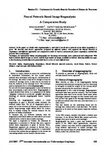
Fig. 1 X-nullcline and periodic orbit of a single oscillator when Ii H(pi − θ) + Si + ρ > 0.
dxi = −(xi − 2)(xi + 1)2 − yi + Ii H(pi − θ) dt + Si + ρ, dyi = ε[γ(1 + tanh(xi /β)) − yi ], dt
(1) (2)
where, θ, ρ, ε, γ, and β are constants: H(x) stands for the Heaviside’s step function, which is defined as H(x) = 1 if x ≥ 0 and H(x) = 0 if x < 0: Ii represents external stimulation, which is a non-zero constant only if an image data exists at pixel i. This dynamics produces the periodic behavior of a single oscillator as shown in Fig. 1. Each oscillator has a firing or non-firing state, and synchronous and asynchronous firing states between oscillators are produced as shown in Fig. 2. A region firing synchronously is extracted as a coherent pattern. Such cooperative behaviors are generated by pi and Si in Eq. (1). The variable pi determines whether oscillator i is a leader; pi = 1 if oscillator i exists within a coherent region, otherwise pi = 0. The leader oscillators play the role of leading the activation of the region. Oscillator blocks which belong to coherent regions can strongly fire by introducing pi . Oscillators which do not belong to coherent regions are hard to fire. This parameter also produces an effect of noise elimination. Coupling input Si determines whether oscillator i belongs to an oscillation region or not, and is given by � Si = Wik H(xk − θx ) − Wz H(z − θxz ), (3) k∈Ni
where Wik is the connection weight from oscillator k to i: z is a variable representing the global inhibitor state: Wz , θx and θxz are constants: Ni is the neighborhood of i. The weight Wik has a non-zero value only if oscillators i and k are stimulated by the input image data. The weights are normalized in order to make oscillators fire at boundaries of coherent regions. If Wik = 0, each oscillator fires asynchronously, otherwise synchronously. Thus, a coherent region is separated from the background. However, the behavior of oscillators belonging to
Fig. 2
Oscillator network states.
coherent patterns apart from each other is not determined by only Wik , so plural coherent regions can be activated at the same time. Such regions should be activated asynchronously with each other. This is attained by the global inhibitor represented by z in Eq. (3). Its dynamics is given by dz = φ(σ − z), dt
(4)
where φ is a constant, and σ = 1 if at least one oscillator exceeds the threshold θz , otherwise σ = 0. Therefore, when the activation level of at least one oscillator exceeds the threshold, the variable z approaches 1. As a result, all oscillators are inhibited by the second term of Eq. (3). Coherent blocks which cannot endure this inhibition fall into the non-firing state. Oscillators of which the excitation is stronger than the inhibition can only stay in the firing state. Thus, oscillators belonging to different coherent patterns fire asynchronously and image segmentation is achieved in the time domain.
ANDO et al.: A NONLINEAR OSCILLATOR NETWORK FOR IMAGE SEGMENTATION
331
2.2 LEGION Model for Gray-Level Images The original LEGION algorithm for gray-level image segmentation is described by a programming language [4], and nonlinear analog dynamics is not used. This is because D.L. Wang, et al., aim at performing such image segmentation with serial computers. In this model, each oscillator is connected to the eight nearest neighbors and the algorithm consists of three steps: initialization, selection, and iteration. In the initialization step, each oscillator is randomly placed on the non-firing states (−2 ≤ xi (t) ≤ −1) and labeled leader if pi = 1. Here, the definitions of parameters pi and Wik are expanded for treating gray-level images: � � � pi = H Wik − θp , (5) k∈Ni
Wik = Imax /(1 + |Ii − Ik |),
(6)
where θp is a constant, and Imax is the maximum intensity value. In the selection step, the leader oscillator that has the maximum x(t) is searched and its state is denoted by xmax (t). It is made fire (xmax (t + 1) = 1) and the states of all other leaders are updated; xj (t + 1) = xj (t) + |xmax (t) + 1|. In the iteration step, if oscillators are stimulated by coupling input, they fire. This process is repeated as long as there are oscillators which can fire by the coupling input. Finally, all firing oscillators are placed on the non-firing state; xi (t) = −2, and the selection step is performed again. Thus, the above procedure serially performs the dynamics of the nonlinear oscillator networks. In the gray-level model, when pixel i and k belong to the identical coherent pattern, weight Wik becomes large because |Ii − Ik | in Eq. (6) is small, and oscillators i and k fire synchronously. Thus, this LEGION model segments gray-level images based on the similarity of pixel intensity. 3.
In this section, we propose a nonlinear oscillator network model for gray-level image segmentation suitable for massively parallel VLSI implementation. The nonlinear function for nonlinear oscillators can be generated using the pulse-modulation approach proposed by the authors [6]. The proposed network model is shown in Fig. 3. This model consists of a 2-D array of oscillators, each of which corresponds to an image pixel, and the global inhibitor as the LEGION model for binary images does. Each oscillator is connected with the eight neighbors and the global inhibitor. The dynamics of the i-th oscillator is given by dxi = −(xi − 2)(xi + 1)2 + ρ − yi + αpi dt + H2 (Si ),
dyi = ε[γ(1 + tanh(xi /β)) − yi ], (8) dt where ρ, α, ε, γ and β are constants: H2 (x) stands for the bipolar Heaviside’s step function, H2 (x) = 1 (x ≥ 0) and H2 (x) = −1 (x < 0): Si , pi and Wik are given by Eqs. (3), (5) and (6), respectively. The global inhibitor state z is given by �� � z=H (9) H(xi − θz ) − 1 , where θz is a constant. The proposed oscillator network model is made by modifying the model for the binary image segmentation. Parameters pi and Wik given in Eqs. (5) and (6)
Modified Oscillator Networks
3.1 Oscillator Networks for Segmenting Gray-Level Images The original LEGION model for gray-level images described in the previous section is unsuitable for massively parallel VLSI implementation because this model is based on serial processing. Although the search for the maximum x(t) can be done by a winner-take-all (WTA) circuit in parallel, it requires a large number of wiring. On the other hand, the LEGION model for binary image segmentation using analog dynamics operates in parallel with local connections.
(7)
Fig. 3
Oscillator network model.
IEICE TRANS. FUNDAMENTALS, VOL.E83–A, NO.2 FEBRUARY 2000
332
for the gray-level image segmentation model are used. The Si term and z are slightly modified. Analog variable Si is changed into a binary one, H2 (Si ), and oscillator i can fire if Si ≥ 0, but it cannot fire if Si < 0. Each oscillator group which belongs to neighboring coherent regions can fire more asynchronously from each other. In order to implement the global inhibitor more easily, analog dynamics of z is simplified. The dynamics for segmentation with the proposed model is as follows: When pixels i and k belong to a coherent pattern, Wik becomes large because |Ii − Ik | is small. Because H2 (Si ) in Eq. (7) becomes 1, oscillators i and k fire synchronously. On the other hand, when they belong to neighboring different coherent patterns, oscillators i and k fire asynchronously because Wik becomes small and H2 (Si ) = 0. Thus, regions corresponding to neighboring different patterns are separated from each other. Asynchronous firing among different coherent regions apart from each other is achieved by the global inhibitor as in the LEGION model for binary images.
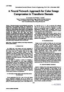
Fig. 4
Input image (8-bit gray-level, 150×150 pixels).
3.2 Numerical Simulation Results In order to implement our proposed model using our pulse-modulation circuit architecture which will be described in Sect. 4, we changed the differential equations into difference ones by using the Euler’s discretization method, and transformed the variable; xi → xi − 2.2 so that the variable range is in the first quadrant in Fig. 1 because pulse-modulation signals are always positive. The dynamics expressed by Eqs. (7) and (8) is changed into the following equations:
(a)
xi (t + 1) − xi (t) = −(xi (t) − 1.2)2 (xi (t) − 4.2) ∆t + ρ + αpi + H2 (Si ) − yi (t), (10) yi (t + 1) − yi (t) = ε[γ(1 + tanh(xi (t)/β − δ)) ∆t − yi (t)].
(11)
We confirmed gray-level real image segmentation by numerical simulation using Eqs. (3), (5), (6), (9), (10) and (11), where α = 0.2, ρ = 0.02, β = 0.1, γ = 6.0, ∆t = 0.15, δ = 22, θxz = 0.1, θx = 0.6, θz = 0.1, θp = 1000, and Wz = 75. Input and result images used in the simulation are shown in Figs. 4 and 5, respectively. As shown in Fig. 5, two faces are segmented independently at different timing. In this way, our proposed oscillator network can segment gray-level images in the time-domain. For VLSI implementation, we have to estimate the calculation precision required for proper operation because only limited accuracy can be obtained in real cir-
(b) Fig. 5
Image outputs.
cuits. We performed simulation adding uniformly random numbers as noise in the calculation of pi , Si , Wik , z, xi and yi . The calculation precision is expressed by bits: Nprec ≡ log2 (Imax /rmax ), where rmax is the maximum amplitude of random numbers. The simulation results are shown in Fig. 6. Our proposed model fails
ANDO et al.: A NONLINEAR OSCILLATOR NETWORK FOR IMAGE SEGMENTATION
333
to segment the image when Nprec = 4, but the segmentation is successful when Nprec = 5. The same results were obtained for different input images. Therefore, the calculation precision required for proper operation is more than 5 bits. This calculation precision can be sufficiently achieved in the pulse modulation circuits [8]. 4.
A Nonlinear Oscillator Network Circuit
4.1 Pulse Modulation Circuits for Nonlinear Analog Dynamical Systems The pulse modulation approaches achieve time-domain analog information processing using pulse signals with a binary amplitude. We can construct analog-digital merged circuits [7] using pulse modulation signals. The approaches include pulse-width modulation (PWM) and pulse-phase modulation (PPM) methods. The PWM approach is suitable for large-scale integration of analog processing circuits because it matches the scaling trend in Si CMOS technology and leads to low voltage operation. This approach also achieves lower power consumption operation than traditional digital circuits because one data is represented by only one state transition. The PPM approach also has the same advan-
tages. However, it requires a reference signal (clock) defining the start time for measuring the phase, whereas a PWM signal includes all of the information in itself. PWM signals are therefore suitable for signal transmission, whereas PPM methods can effectively be used in local circuits. PWM/PPM circuits [6], [9] can implement arbitrary nonlinear dynamics as shown in Fig. 7. The input voltage Vin is linearly transformed into a PWM signal Va having a pulse width of T by comparing it with a linearly ramped signal Vramp . Then, the PWM signal is transformed into a PPM signal Vb . The PPM signal switches a current source modulated by nonlinear non-monotone waveform f (t). The current source supplies charges equal to f (T )∆t to a serially connected capacitor C. As a result, the voltage of the capacitor node, Vout , is nonlinearly modulated; the voltage change is f (T )∆t/C. If the output voltage is fed back to the input, this circuit can implement discrete-time dynamics. This is an approximate solution of the corresponding differential equation if the voltage change is very small. Thus, we can obtain nonlinearly modulated voltages and PWM/PPM signal trains following arbitrary nonlinear dynamics. 4.2 A Nonlinear Oscillator Circuit
(a) Image output for Nprec = 4
A nonlinear oscillator circuit using the PWM/PPM method is shown in Fig. 8. This circuit implements the dynamics expressed by Eqs. (10) and (11). The values of xi and yi are represented by voltages Vxi and Vyi , and are stored as charges in capacitors Cxi and Cyi , respectively. The third-order and tanh functions of xi in Eqs. (10) and (11) are generated by conversion from voltage into PPM signals and the nonlinearly modulated current sources. The PPM signals switch current sources, and small charges corresponding to finite differences in Eqs. (10) and (11) are injected into or extracted from Cxi and Cyi in each time step. A threshold function H(·) used in Eqs. (3), (5), (9) and (10) is generated by using a comparator, and
(b) Image output for Nprec = 5 Fig. 6
Image outputs after adding noise.
Fig. 7
Nonlinear transformation using pulse modulation.
IEICE TRANS. FUNDAMENTALS, VOL.E83–A, NO.2 FEBRUARY 2000
334
Fig. 8
Oscillator circuit.
summations and multiplications are performed by using switched current sources as shown in Fig. 8. Circuit simulation (SPICE) of one oscillator circuit was performed, where pi was fixed at positive, and Si was changed as shown in Fig. 9. The device parameters used were based on a 0.6 µm CMOS process, the supply voltage was 5.0 V, and the clock period was 1 µs. The simulation result shown in Fig. 9 demonstrates the expected oscillation and that the oscillator state is controlled by Si . Thus, it was confirmed that the proposed oscillator circuit precisely implements the nonlinear dynamics shown in Eqs. (10) and (11). According to this result, image segmentation can be performed within the order of 100 µs. 4.3 A Connection Weight Circuit The connection weights expressed by Eq. (6) are realized by a circuit shown in Fig. 10 (a). The circuit simulation result is shown in Fig. 10 (b). Voltage Vxi representing image intensity Ii is linearly transformed into a pulse with a width of Ti by comparator compi1 . The absolute difference between Ii and the neighboring pixel data Ik , |Ii − Ik |, is generated by an XOR logic gate as a PWM pulse Tik . Then, the pulse is transformed into voltage Va , and Va is compared with reference signal voltage Vref b that varies in the time-domain: Vref b (t) = 1/t−1. The pulse width of the comparator output, Wik , is obtained by Vref b (Wik ) = 1/Wik − 1 = Va . Since Va is proportional to |Ii − Ik |, Wik expressed by Eq. (6) is obtained, and the results for eight neighborhoods are stored in capacitors Cik , (k = 1, · · · , 8), respectively. 4.4 A Global Inhibitor Circuit The global inhibitor unit expressed by Eq. (9) is realized by a circuit shown in Fig. 11. The terminal voltage
Fig. 9
SPICE simulation results of oscillator circuit.
of capacitor Cz , Vz , is initialized at GND level by the reset signal at a start time of iteration steps. Voltage Vxi is compared with reference voltage θz , and comparator output Va is “High” only when Vxi > θz . This process is performed for all oscillators at the same time. Therefore, Vz becomes “High” if Vxi > θz for at least one oscillator. In this circuit, we can commonly use a comparator for the connection weight circuit and for the global inhibitor circuit. 4.5 Estimation of Circuit Size From the SPICE simulation, the circuit area and power consumption for an oscillator are estimated to be 150 × 150 µm sq. and 150 µW at a power supply voltage of 5 V, respectively. Therefore, we can integrate 100 × 100 pixels in a chip with power consumption of 1.5 W if the core chip area of 15 × 15 mm sq. is available. Using this chip, we can manage to segment a natural image data. The main factor in the power consumption is short-circuit current of the CMOS inverters used in the comparators shown in Figs. 7 and 8. This will be
ANDO et al.: A NONLINEAR OSCILLATOR NETWORK FOR IMAGE SEGMENTATION
335
Fig. 10
Weight connection circuit.
allel VLSI implementation. We confirmed image segmentation using the proposed model and estimated the calculation precision required for proper operations to be 5 bits by numerical simulation. We proposed PWM/PPM circuits for nonlinear oscillator networks, and confirmed the basic operation by circuit simulation. From the estimation of circuit size and power consumption, we can expect to make a chip for natural image segmentation. Acknowledgments
Fig. 11
Global inhibitor circuit.
reduced by using more sophisticated circuit design. If the supply voltage is 3.3 V, the power consumption can be reduced to around 300 mW. 5.
Conclusion
We proposed an oscillator network model for graylevel image segmentation suitable for massively par-
This work was supported by Grant-in-aid #11555102 for Scientific Research from the Ministry of Education, Science and Culture of Japan. This work was also supported in part by Grants-in-aid for the Core Research for Evolutional Science and Technology (CREST) from the Japan Science and Technology Corporation (JST). References [1] R.M. Haralick and L.G. Shapiro, “Image segmentation techniques,” Computer Vision, Graphics and Image Processing, vol.29, pp.100–132, 1985. [2] R. Adams and L. Bischof, “Seeded region growing,” IEEE Trans. Pattern Anal. & Mach. Intell., vol.16, no.6, pp.641– 647, 1994.
IEICE TRANS. FUNDAMENTALS, VOL.E83–A, NO.2 FEBRUARY 2000
336
[3] D.L. Wang and D. Terman, “Locally excitatory globally inhibitory oscillator networks,” IEEE Trans. Neural Networks, vol.6, no.1, pp.283–286, 1995. [4] D.L. Wang and D. Terman, “Image segmentation based on oscillatory correlation,” Neural Computation, vol.9, no.4, pp.805–836, 1997. [5] P.S. Linsay and D.L. Wang, “Fast numerical integration of relaxation oscillator networks based on singular limit solutions,” IEEE Trans. Neural Networks, vol.9, no.3, pp.523– 532, 1998. [6] T. Morie, S. Sakabayashi, H. Ando, M. Nagata, and A. Iwata, “Pulse modulation circuit techniques for nonlinear dynamical systems,” Proc. Int. Symp. on Nonlinear Theory and its Application (NOLTA ’98), pp.447–450, Crans-Montana, Sept. 1998. [7] A. Iwata and M. Nagata, “A concept of analog-digital merged circuit architecture for future VLSI’s,” IEICE Trans. Fundamentals, vol.E79-A, no.2, pp.145–157, Feb. 1996. [8] T. Morie, J. Funakoshi, M. Nagata, and A. Iwata, “An analog-digital merged neural circuit using pulse width modulation technique,” IEICE Trans. Fundamentals, vol.E82-A, no.2, pp.356–363, Feb. 1999. [9] H. Ando, T. Morie, M. Nagata, and A. Iwata, “Oscillator networks for image segmentation and their circuits using pulse modulation methods,” Proc. 5th Int. Conf. on Neural Information Processing (ICONIP ’98), pp.586–589, Kitakyushu, Oct. 1998.
Hiroshi Ando received the B.S. and M.E. degrees in electronics engineering from Hiroshima University, Hiroshima, Japan, in 1997, 1999, respectively. He is currently working towards the Ph.D. degree in electronics engineering. His main research interests include hardware implementation of image processing models.
Takashi Morie received the B.S. and M.S. degrees in physics from Osaka University, Osaka, Japan, and the Dr. Eng. degree from Hokkaido University, Sapporo, Japan, in 1979, 1981, and 1996, respectively. In 1981, he joined Nippon Telegraph and Telephone Corporation (NTT), where he worked as a researcher at LSI laboratories. From 1995 to 1997, he was engaged in the development of subscriber line interface circuits for digital switching systems. Since 1997 he has been an Associate Professor of Electrical Engineering at Hiroshima University, Higashi-Hiroshima, Japan. His main interest is in the area of VLSI implementation of neural networks, analog-digital merged architecture, and new functional devices. Dr. Morie is a member of the Japan Society of Applied Physics, the Japanese Neural Network Society.
Makoto Nagata received the B.S. and M.S. degrees in physics from Gakushuin University, Tokyo, Japan, in 1991 and 1993, respectively. From 1994 to 1996 he was a Research Associate at the Research Center for Integrated Systems, Hiroshima University. He is currently a Research Associate with the Department of Electrical Engineering, Hiroshima University. His research interests include the development of AnalogDigital merged circuit architecture, modeling techniques of circuits and cross-talk noises in analog HDL for Mixed Signal LSI design, VLSI implementation of neural networks, and also the area of new functional devices. He is a member of the IEEE.
Atsushi Iwata received the B.E., M.S. and Ph.D. degrees in electronics engineering from Nagoya University, Nagoya, Japan, in 1968, 1970, and 1994 respectively. From 1970 to 1993, he was with the Electrical Communications Laboratories, Nippon Telegraph and Telephone Corporation. Since 1994 he has been a professor of Electrical Engineering at Hiroshima University. His research is in the field of integrated circuit design where his interests include, circuit architecture and design techniques for analog-to-digital and digital-to-analog converters, digital signal processors, ultra high-speed telecommunication IC’s, and large-scale neural network implementations. He received an Outstanding Panelist Award at the 1990 International SolidState Circuits Conference. Dr. Iwata is a member of the Institute of Electrical and Electronics Engineers.