IJCV&B - PREPRINT
A parallel algorithm for solving complex multibody problems with stream processors Alessandro Tasora Dept. of Mechanical Engineering University of Parma Parma, Italy Email:
[email protected]
Dan Negrut Dept. of Mechanical Engineering University of Wisconsin–Madison Madison, WI 53706 Email:
[email protected]
February 6, 2009
Abstract This paper describes a numerical method for the parallel solution of the differential measure inclusion problem posed by mechanical multibody systems containing bilateral and unilateral frictional constraints. The method proposed has been implemented as a set of parallel algorithms leveraging NVIDIA’s Compute Unified Device Architecture (CUDA) library support for multi-core stream computing. This allows the proposed solution to run on a wide variety of GeForce and TESLA NVIDIA graphics cards for high performance computing. Although the methodology relies on the solution of cone complementarity problems known to be fine-grained in terms of data dependency, a suitable approach has been developed to exploit parallelism with low overhead in terms of memory access and threads synchronization. Since stream multipocessors are becoming ubiquitous as embedded components of next-generation graphic boards, the solution proposed represents a cost-efficient way to simulate the time evolution of complex mechanical problems with millions of parts and constraints, a task that used to require powerful supercomputers. The proposed methodology facilitates the analysis of extremely complex systems such as granular material flows and off-road vehicle dynamics. Keywords: Dynamics, GP-GPU programming, friction, CUDA, multibody.
Introduction The development of parallel algorithms for simulation-based science and engineering has represented one of the most complex challenges in the field of numerical computing. Until recently the massive computational power of parallel supercomputers has been available to a relatively small number of research groups in a select number of research facilities, thus limiting the number of applications approached and the impact of high performance computing. This scenario is rapidly changing due to a trend set by general-purpose computing on the graphics processing unit (GPU). The libraries CUDA from NVIDIA and CTM from ATI allow one to use the streaming microprocessors mounted in high-end graphics cards as general-purpose computing hardware 1 . In the last two years these microprocessors evolved from basic arrays of graphics units capable of executing simple 3D shading programs on each pixel of the frame buffer to full-featured multiprocessors used for scientific computing. Presently, the raw computational power of these multiprocessors (such as the GT200 from NVIDIA) can reach one Teraflop, that is hundreds of times the throughput of a modern scalar CPU. This is achieved thanks to the large array of scalar units working in parallel and each following a Single Instruction Multiple Data (SIMD) paradigm. GP-GPU computing has been very vigorously promoted by NVIDIA since the release of the CUDA development platform in early 2007. CUDA [1] is an application interface for software development targeted to run on the G80 family of GPUs. A large number of scientific applications has been developed using CUDA, most of them dealing 1 Hence
the name GP-GPU (General Purpose Graphical Processing Unit) which is often used to denote this computational paradigm.
1
with problems that are quite easily parallelizable such as molecular dynamics or signal processing. Very few GP-GPU projects are concerned though with the dynamics of multibody systems and the two most significant are the Havok and the Ageia physics engines. Both are commercial and proprietary libraries used in the video-game industry and their algorithmic details are not public. Typically, these physics engines trade precision for efficiency as the priority is in speed rather than accuracy. In this context, the goal of this work was to implement a general-purpose multibody solver on GP-GPU multiprocessors backed by convergence results that guarantee the accuracy of the solution. Specifically, a parallel version was implemented of a numerical scheme presented in [2, 3], which can robustly and efficiently approximate the bilaterally constrained dynamics of rigid bodies undergoing frictional contacts. The field of numerical methods for the simulation of multibody system in the presence of friction and contact/impact phenomena is an area of active research. Results reported in [4] indicate that the most widely used commercial software package for multibody dynamics simulation runs into significant difficulties when handling simple problems involving hundreds of contact events, whereas cases with thousands of contacts become intractable. The method embraced in this work can solve efficiently problems with millions of contacts on a simple scalar CPU of the Pentium family, and improved performance can be obtained with the GP-GPU version proposed herein. Unlike the so-called penalty or regularization methods, where the frictional interaction can be represented by a collection of stiff springs combined with damping elements that act at the interface of the two bodies [5, 6, 7, 8], the approach embraced herein relies on a different mathematical framework. Specifically, the algorithms rely on timestepping procedures producing weak solutions of the differential variational inequality (DVI) problem that describes the time evolution of rigid bodies with impact, contact, friction, and bilateral constraints. When compared to penaltymethods, the DVI approach has a greater algorithmic complexity, but avoids the small time steps that plague the former approach. Early numerical methods based on DVI formulations can be traced back to [9, 10, 11], while the DVI formulation has been recently classified by differential index in [12]. Recent approaches based on time-stepping schemes have included both acceleration-force linear complementarity problem (LCP) approaches [13, 14, 15] and velocity-impulse LCP-based time-stepping methods [16, 17, 18, 19]. The LCPs, obtained as a result of the introduction of inequalities in time-stepping schemes for DVI, coupled with a polyhedral approximation of the friction cone must be solved at each time step in order to determine the system state configuration as well as the Lagrange multipliers representing the reaction forces [10, 16]. If the simulation entails a large number of contacts and rigid bodies, as is the case of part feeders, packaging machines, and granular flows, the computational burden of classical LCP solvers can become significant. Indeed, a well-known class of numerical methods for LCPs based on simplex methods, also known as direct or pivoting methods [20], may exhibit exponential worst-case complexity [21]. They may be impractical even for problems involving as little as a few hundred bodies when friction is present [22, 23]. Moreover, the threedimensional Coulomb friction case leads to a nonlinear complementarity problem (NCP): the use of a polyhedral approximation to transform the NCP into an LCP introduces artificial anisotropy in friction cones [16, 15, 17]. This discrete and finite approximation of friction cones is one of the reasons for the large dimension of the problem that needs to be solved in multibody dynamics with frictional contact. In order to circumvent the limitations imposed by the use of classical LCP solvers and the limited accuracy associated with polyhedral approximations of the friction cone, a parallel fixed-point iteration method with projection on a convex set has been proposed, developed, and tested in [3]. The method is based on a time-stepping formulation that solves at every step a cone constrained optimization problem [24]. The time-stepping scheme has been proved to converge in a measure differential inclusion sense to the solution of the original continuous-time DVI. This paper illustrates how this problem can be solved in parallel by exploiting the parallel computational resources available on NVIDIA’s GPU cards.
Formulation of Multibody Dynamics The formulation of the equations of motion, that is the equations that govern the time evolution of a multibody system, is based on the so-called absolute, or Cartesian, representation of the attitude of each rigid body in the system. £ ¤T ∈ R7nb and their The state of the system is denoted by the generalized positions q = rT1 , ǫT1 , . . . , rTnb , ǫTnb ¤ £ T T T ∈ R7nb , where nb is the number of bodies, rj is the absolute position time derivatives q˙ = r˙ 1 , ǫ˙1 , . . . , r˙ Tnb , ǫ˙Tnb of the center of mass of the j-th body and the quaternions ǫj are used to represent rotation and to avoid singularities. ˙ it is more advantageous to work with angular velocities: the However, instead of using quaternion derivatives in q, ¤T £ ¯ nTb ¯ 1T , . . . , r˙ Tnb , ω ∈ R6nb . Note that the method described will use the vector of generalized velocities v = r˙ T1 , ω 2
generalized velocity can be easily obtained as q˙ = L(q)v, where L is a linear mapping that transforms each ω ¯ i into the corresponding quaternion derivative ǫ˙i by means of the linear algebra formula ǫ˙i = 12 GT (q)¯ ωi , with 3x4 matrix G(q) as defined in [25]. Given the velocities considered, for a system of rigid bodies the generalized mass matrix M remains constant and diagonal. Denoting by f A (t, q, v) the set of applied, or external, generalized forces, the second order differential equations that govern the time evolution of the multibody system expressed in matrix notation assume the form Mv˙ = f A (t, q, v).
Bilateral constraints Bilateral constraints represent kinematic pairs, for example spherical, prismatic or revolute joints, and can be expressed as holonomic algebraic equations constraining the relative position of two bodies. Assuming a set B of constraints is present in the system, they lead to a collection of scalar equations: Ψi (q, t) = 0,
i ∈ B.
(1)
For instance, a ball joint requires three of these scalar equations. Assuming smoothness of constraint manifold, T Ψi (q, t) can be differentiated to obtain the Jacobian ∇q Ψi = [∂Ψi /∂q] . All bilateral constraints must also be satisfied at the velocity level. This requirement stems from the full timederivative of the i-th constraint equation: dΨi (q, t) =0 dt
⇒
∂Ψi ∂Ψi ∂Ψi ∂Ψi q˙ + = ∇q ΨTi q˙ + = ∇q ΨTi L(q)v + =0 ∂q ∂t ∂t ∂t
Defining ∇ΨTi = ∇q ΨTi L(q) ,
(2)
the constraints are consistent at velocity-level provided the following equation is satisfied: ∇ΨTi v + Note that the
∂Ψi ∂t
∂Ψi =0 ∂t
(3)
is nonzero only for rheonomic constraints (motors, actuators, imposed trajectories).
Unilateral constraints Given a large number of rigid bodies with different shapes, modern collision detection algorithms are able to find efficiently a set of contact points, that is points where a gap function Φ(q) can be defined for each pair of near-enough shape features. Where defined, such a gap function must satisfy the non-penetration condition Φ(q) ≥ 0 for all contact points. Note that a signed distance function, differentiable at least up to some value of the interpenetration [26], can be easily defined if bodies are smooth and convex [27]. However, this is not always possible, for instance when dealing with concave or faceted shapes often used to represent parts of mechanical devices. In this case the gap function Φ(q) can be non-smooth or not well defined. Without loss of generality, for sufficiently small penetration, the following assumption can be made on the geometrical constraints: any contact is described by a gap function Φ(q) that is twice continuously differentiable. Most often, when one deals with convex geometries and small numerical integration step-sizes, this assumption is easily verified. The proposed implementation uses the robust and efficient Gilbert-Johnson-Keerthi (GJK) algorithm [28] to find the contact points between convex shapes 2 .
Friction Friction is introduced for each unilateral contact constraint present in the multibody system. When a contact i is active, that is Φi (q) = 0, a normal force and a tangential force act on each of the two bodies at the contact point. We use the 2 An efficient way to deal with concave geometries is to represent them as clusters of smaller convex shapes, performing a concave decomposition before the simulation starts. In this way, the GJK algorithm can be used on the convex subparts, for most geometries without significant impact on the robustness of the method.
3
classical Coulomb friction model to define these forces [17]. If the contact is not active, that is Φi (q) > 0, no friction forces exist. This implies that the mathematical description of the model leads to a complementarity problem [16]. Given two bodies in contact A and B, let ni be the normal at the contact pointing toward the exterior of the body of lower index, which by convention is considered to be body A. Let ui and wi be two vectors in the contact plane such that ni , ui , wi ∈ R3 are mutually orthonormal vectors. The frictional contact force is impressed on the system by means of multipliers γ bi,n ≥ 0, γ bi,u , and γ bi,w , which lead to the normal component of the force Fi,N = γ bi,n ni and the tangential component of the force Fi,T = γ bi,u ui +b γi,w wi . The Coulomb model imposes the following nonlinear constraints: γ bi,n
µi γ bi,n
≥ 0, γ³i,n = 0, q ´ q Φi (q) ≥ 0, Φi (q)b 2 2 2 +γ 2 = 0, ≥ γ bi,u + γ bi,w , ||vi,T || µi γ bi,n − γ bi,u bi,w hFi,T , vi,T i = −||Fi,T || ||vi,T ||
where vi,T is the relative tangential velocity at contact i. Defining by h , i the inner product of two vectors, the constraint hFi,T , vi,T i = −||Fi,T || ||vi,T || requires that the tangential force be opposite to the tangential velocity. Note that the friction force depends on the friction coefficient µi ∈ R+ . The original Coulomb model distinguishes between static µs and kinetic µk friction coefficients. For simplicity, in this paper an assumption is made that these coefficients are the same. If needed, it is possible to extend the method to make this distinction or also consider more complex constitutive equations such as the Stribeck friction model [29]. The first part of the constraint can be restated as bi,n ni + γ bi,u ui + γ bi,w wi ∈ Υ, Fi = Fi,N + Fi,T = γ
(4)
where Υ is a cone in three dimensions, whose slope is tan−1 µi . This results in the friction force being dissipative. An equivalent convenient way of expressing this constraint is by using the maximum dissipation principle: (b γi,u , γ bi,w ) = √
argmin 2 +b 2 ≤µ γ γ b i,u γi,w i b i,n
T vi,T (b γi,u ui + γ bi,w wi ) .
(5)
In fact, the the first-order necessary Karush-Kuhn-Tucker conditions [30] for the minimization problem (5) correspond to the Coulomb model above [31, 11].
The overall model We assume that at time t several bodies are touching, interpenetrating or separated by a distance smaller than a threshold δ > 0, so that a set A of relevant contact constraints can be assembled: A(q, δ) = {i | i ∈ {1, 2, . . . , p} , Φi (q) ≤ δ } , Shapes which are separated by larger distances than the δ threshold are not considered for frictional contact analysis to avoid a wasting of computational resources. It is also assumed that there is a set of active bilateral constraints B, acting on the rigid bodies. Each constraint i ∈ B transmits reactions to the connected bodies by means of a multiplier γ bi,b . Considering the effects of both A(q, δ) frictional contacts and B bilateral constraints, the time evolution of the dynamical system is governed by the following differential problem with set-valued functions and complementarity constraints, which is equivalent to a diferential variational inequality [32]: q˙ Mv˙
= L(q)v = f (t, q, v) +
P
i∈A(q,δ)
i∈B i ∈ A(q, δ) (b γi,u , γ bi,w )
(b γi,n Di,n + γ bi,u Di,u + γ bi,w Di,w ) +
: Ψi (q, t) = 0 : γ bi,n ≥ 0 ⊥ Φi (q) ≥ 0, and T v (b γ bi,w Di,w ) = argmin i,u Di,u + γ √ µi γ b i,n ≥
P
i∈B
γ bi,b ∇Ψi
(6)
(b γi,u )2 +(b γi,w )2
The tangent space generators Di = [ Di,n , Di,u , Di,w ] ∈ R6nb ×3 are defined as £ DTi = 0 . . . −ATi,p ATi,p AA˜¯si,A 0 . . . 0 ATi,p −ATi,p AB ˜¯si,B 4
...
0
¤
,
(7)
i-th contact Body
A
ui
Body
B
ni
y
si,B
wi
z x
si,A y
x
rB y
z
rA
x z
0
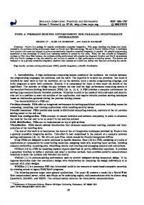
Figure 1: Contact i between two bodies A, B ∈ {1, 2, . . . , nb } where we use Ai,p = [ni , ui , wi ] as the R3×3 matrix of the local coordinates of the ith contact, and introduce the vectors ¯si,A and ¯si,B for representing the contact point positions in body-relative coordinates, as illustrated in Figure (1). The Coulomb model used in this work is the predominant model used in the engineering literature to describe dry friction. Unfortunately, the model may be inconsistent: there exist configurations for which the resulting problem does not have a solution [13, 19]. This situation has led to the need to explore weaker formulations where the forces are measures and Newton’s law is satisfied in a measure differential inclusion sense [19]. It has been shown that solutions in that sense do exist and can be found by time-stepping schemes [33].
Time-stepping scheme We formulate the dynamical problem in terms of measure differential inclusions [19], whose numerical solution can be obtained using the following time-stepping scheme based on the solution of a complementarity problem at each time step. Given a position q(l) and velocity v(l) at the time-step t(l) , the numerical solution is found at the new time-step (l+1) t = t(l) + h by solving the following optimization problem with equilibrium constraints [2]: X X M(v(l+1) − v(l) ) = hf (t(l) , q(l) , v(l) ) + (γi,n Di,n + γi,u Di,u + γi,w Di,w ) + γi,b ∇Ψi , (8) i∈A(q (l) ,δ)
i∈B
:
i ∈ A(q (l) , δ)
:
(γi,u , γi,w )
=
∂Ψi 1 Ψi (q(l) , t) + ∇ΨTi v(l+1) + =0 h ∂t 1 0 ≤ Φi (q(l) ) + DTi,n v(l+1) ⊥ γni ≥ 0, and h vT (γi,u Di,u + γi,w Di,w ) , argmin √
µi γi,n ≥
q(l+1)
i∈B
(9) (10) (11)
2 +γ 2 γi,u i,w
= q(l) + hL(q(l) )v(l+1) .
(12)
Here, γs represents the constraint impulse of a contact constraint, that is, γs = hb γs , for s = n, u, w. The h1 Φi (q(l) ) term achieves constraint stabilization, and its effect is discussed in [34]. Similarly, the term h1 Φi (q(l) ) achieves
5
stabilization for bilateral constraints. The scheme converges to the solution of a measure differential inclusion [24] when the step size h → 0. Several approaches can be used to solve (8)-(11). Some authors suggested to approximate friction cones as faceted pyramids, so that the system of equations above, originally a Nonlinear Complementarity Problem (NCP), turns into a Linear Complementarity Problems (LCP) [17]. The resulting LCPs are solved using algorithms based on the so-called pivoting methods or simplex methods. These numerical approaches that belong to the class of direct methods are computationally expensive, and their complexity class is in the worst case exponential [22]. Alternatively, the problem is cast as a monotone optimization problem by introducing a relaxation over the complementarity constraints. Specifically, the time-stepping scheme is modified by replacing Eq. (10) with q 1 (13) i ∈ A(q (l) , δ) : 0 ≤ Φi (q(l) ) + DTi,n v(l+1) − µi (vT Di,u )2 + (vT Di,w )2 ⊥ γni ≥ 0 . h Nonetheless, as h → 0 the solution of the modified time-stepping scheme will approach the solution of the same measure differential inclusion as the original scheme [24]. It has been shown [3] that the modified scheme is a Cone Complementarity Problem (CCP), which can be solved efficiently by a family of iterative numerical methods that rely on projected contractive maps. One such algorithm is discussed below; it fits well into a parallel computing paradigm since it requires little data interdependency, similarly to a projected-Jacobi fixed-point method. Omitting for brevity some of the details discussed in [3], the algorithm makes use of the following vectors: ˜ k bi bi
≡ Mv(l) + hf (t(l) , q(l) , v(l) ) ½ ¾T 1 (l) ≡ Φi (q ), 0, 0 i ∈ A(q (l) , δ), h ∂Ψi 1 Ψi (q(l) , t) + , i∈B ≡ h ∂t
(14) (15) (16)
The solution, in terms of dual variables of the CCP (the multipliers), is obtained by iterating the following steps until convergence: ∀i ∈ A(q (l) , δ) : δir+1 γir+1 ∀i ∈ B : δir+1 γir+1
= γir − ωηi DiT M−1
X
Dz γzr +
z∈A(q (l) ,δ)
¡ ¢ = λΠΥi δir+1 + (1 − λ)γir .
= γir − ωηi ∇ΨTi M−1
z∈B
˜ + bi ∇Ψz γzr + k
(17) (18)
X
z∈A(q (l) ,δ)
= λδir+1 + (1 − λ)γir .
X
Dz γzr +
X
z∈B
˜ + bi ∇Ψz γzr + k
(19) (20)
The iterative process uses the projection operator ΠΥi (·) [2], which is a non-expansive map ΠΥi : R3 → R3 acting on the triplet of multipliers associated with the i-th contact. Thus, if the multipliers fall into the friction cone, they are not modified; if they are in the polar cone, they are set to zero; in the remaining cases they are projected orthogonally onto the surface of the friction cone. The overrelaxation factor ω and the λ and η parameters are adjusted to control the convergence. Good default values for η are ηi = 3/Trace(DiT M−1 Di ) for i ∈ A(q (l) , δ), and ηi = 1/(∇ΦTi M−1 ∇Φi ) for i ∈ B. When dealing exclusively with bilateral constraints these choices lead to the classical Jacobi fixed-point method. In regards to ω and λ, extensive numerical experiments suggest that choosing ω = 0.3 and λ = 1 typically leads to good convergence speed. The interested reader is referred to [3] for a proof of the convergence of this method. Note that using Eqs.(8) and (14), one can rewrite the iteration in a more compact form: £ ¡ ¢¤ ∀i ∈ A(q (l) , δ) : γir+1 = λΠΥi γir − ωηi DiT vr + bi + (1 − λ)γir (21) £ r ¡ ¢¤ r+1 T r r = λ γi − ωηi ∇Ψi v + bi + (1 − λ)γi (22) ∀i ∈ B : γi 6
In this case, at each iteration, before repeating (21) and (22), velocities v(l+1) are updated as X X ˜ vr+1 = M−1 Dz γzr+1 + ∇Ψz γzr+1 + k
(23)
z∈B
z∈A(q (l) ,δ)
Note that the superscript (l + 1) was omitted for brevity. Good accuracy in the CCP solution is typically obtained after less than one hundred iterations. Note that iterating through (21), (22) and (23), also yields the primal variables (the velocities) at the end of the procedure with no additional effort. The following pseudocode of Algorithm 1 shows how the iteration is implemented on a serial computing architecture: Algorithm 1: Inner Iteration Loop 1. For i ∈ A(q, δ), evaluate ηi = 3/Trace( DTi M−1 Di ). 2. For i ∈ B, evaluate ηi = 1/(∇ΦTi M−1 ∇Φi ).
3. Warm start: if some initial guess γ ∗ is available for multipliers, then set γ 0 = γ ∗ , otherwise γ 0 = 0. P P ˜. 4. Initialize velocities: v0 = i∈A M−1 Di γi0 + i∈B M−1 ∇Φi γi,b 0 + M−1 k 5. For i ∈ A(q(l) , δ), compute¡ changes in for contact constraints: ¡ multipliers ¢¢ γir+1 = λ ΠΥi γir − ωηi DTi vr + bi + (1 − λ)γir ; ∆γir+1 = γir+1 − γir ; ∆vi = M−1 Di ∆γir+1 .
6. For i ∈ B, compute changes in multipliers for bilateral constraints: ¡ ¡ ¢¢ γir+1 = λ γir − ωηi ∇ΨTi vr + bi + (1 − λ)γir ; ∆ γir+1 = γir+1 − γir ; ∆vi = M−1 ∇Ψi ∆γir+1 . 7. Apply updates to the velocity P vector: P vr+1 = vr + i∈A ∆vi + i∈B ∆vi
8. r := r + 1. Repeat from 5 until convergence, or until r > rmax .
The stopping criterion is based on the value of the velocity update. The overall algorithm that provides an approximation to the solution of Eqs. (8) through (12) relies on Algorithm 1 and requires the following steps: Algorithm 2: Outer, Time-Stepping, Loop 1. Set t = 0, step counter l = 0, provide initial values for q(l) and v(l) . 2. Perform collision detection between bodies, obtaining nA possible contact points within a distance δ. For each contact i, compute Di,n , Di,u , Di,w ; for each bilateral constraint compute the residual Φi (q), which also provides bi . 3. For each body, compute forces f (t(l) , q(l) , v(l) ). 4. Use Algorithm 1 to solve the cone complementarity problem and obtain unknown impulse γ and velocity v(l+1) . 5. Update positions using q(l+1) = q(l) + hL(q(l) )v(l+1) . 6. Increment t := t + h, l := l + 1, and repeat from step 2 until t > tend These two algorithms have been implemented on serial computing architectures and proved to be reliable and efficient. In the following the time-consuming part of the methodology, that is the CCP iteration of Algorithm 1, will be reformulated to take advantage of the parallel computing resources available on commodity GPUs. 7
Parallel computation on the GPU Currently, high-end GPUs offer floating-point parallel computing power close to one Teraflop, thus exceeding those of multi-core CPUs. This computational resource, usually devoted to the execution of pixel shading fragments for the rendering of OpenGL or DirectX three dimensional visualization, can be also exploited for scientific computation. Earlier experiments with scientific computing on the GPU required an intricate programming technique because GPU hardware and software was meant for real-time graphical visualization only. The developer had to use OpenGL calls to reformulate small scientific computation programs in the GLSL shading language native to the graphics board. These programs were executed with data organized in rectangular textures, with RGBA color representing some scientific data. In this way, the output was rendered in parallel, pixel by pixel, by the pixel-shading processors3 into a frame buffer which was never visualized on the screen; the RGBA colors of that frame buffer would in fact represent the output of the parallel scientific computation. To alleviate the difficulty of this programming model NVIDIA recently proposed a development environment, called CUDA [1], which allows general-purpose programming on the GPU. Basically, the programmer can write algorithms using a subset of the C++ language, which can be compiled into machine code and executed on the GPU device. The GPU executes the same kernel on each parallel thread which in turn operates over data structures called streams, hence the name streaming processor. This computational architecture is called SIMT, Single Instruction Multiple Thread, and it can be considered an advanced form of SIMD Single Instruction Multiple Data architecture according to the Flynn taxonomy [35]. To efficiently execute hundreds of threads in parallel, GPU multiprocessors are hardware multithreaded: they can manage thousands of concurrent threads with almost zero scheduling overhead, so that hardware switching between threads is used effectively to hide the latency to memory access operations. We implemented our code on graphics board of the 9800 GX2 family, from NVIDIA. Each board features two GPU processors, for a total of 256 streaming processors and capable of running 24,576 live threads. The processed data resides in the 2GB of DDR3 device memory. The basic idea is that, at each simulation step, the CPU uploads data into the GPU memory, launches a kernel to be performed simultaneously on many parallel GPU threads, and gathers the results of the computations by downloading select portions of the GPU memory back into the host RAM. Out of the entire computational time, the time slice spent on the CPU should be as small as possible to exploit the scalable nature of the GPU parallelism. For the problem at hand, not all of the multibody simulation has been ported on the GPU. In particular, this is the case of the collision detection engine, which is still executed on the CPU and becomes the bottleneck of the entire simulation. Nonetheless, the proposed algorithm fits well into the GPU multithreaded model because the computation can be split in multiple threads each acting on a single contact or kinematic constraint.
Buffers for data structures In the proposed approach, the data structures on the GPU are implemented as large arrays (buffers) to match the execution model associated with NVIDIA’s CUDA. Specifically, threads are grouped in rectangular thread blocks, and thread blocks are arranged in rectangular grids. Four main buffers are used: the contacts buffer, the constraints buffer, the reduction buffer, and the bodies buffer. When designing the data structures of these buffers, special care should be paid to minimize the memory overhead caused by repeated transfers of large data structures. Moreover, data structures should be organized to exploit fast GPU coalesced memory access to fetch data for all parallel threads in a warp, which is a set of 32 threads all running simultaneously in parallel. Provided that bytes are contiguous and that the k th thread accesses the k th element in the data structure, up to 512 bytes can be fetched in one operation by a warp of threads. Failing to perform coalesced memory access may slow the kernel significantly. Numerical experiments show that for high memory throughput, it is better to pad the data into a four-float width structure even at the cost of wasting memory space when several entries end up not being used. Also, the variables in the data structures are organized in a way that minimizes the number of fetch and store operations. This approach maximizes the arithmetic intensity of the kernel code, as recommended by the CUDA development guidelines. In the actual implementation of the method, the data structure for the contacts has been mapped into columns of four floats as shown in Fig. 2. Each contact will reference its two touching bodies through the two pointers BA and 3 Earlier models of GPU implemented two kinds of parallel execution units, the pixel processors and the vertex processors; the former were more easily adapted to scientific computing. Modern GPUs, instead, implement a single type of execution units (called streaming processors or thread processors) which can be used for pixel shading, vertex processing, as well as for generic scientific computation.
8
BB , in the fourth and seventh rows of the contact data structure. There is no need to store the entire Di matrix for the ith contact because it has zero entries for most of its part, except for the two 12x3 blocks corresponding to the coordinates of the two bodies in contact. In fact, once the velocities of the two bodies r˙ Ai , ωAi , r˙ Bi and ωBi have been fetched, the product DTi vr in step 5 of Algorithm 1 can be performed as (24) DTi vr = DTi,vA r˙ Ai + DTi,ωA ωAi + DTi,vB r˙ Bi + DTi,ωB ωBi with the adoption of the following 3x3 matrices DTi,vA = −ATi,p
DTi,ωA DTi,vB DTi,ωB
=
= =
ATi,p AA˜¯si,A ATi,p −ATi,p AB ¯˜si,B
(25a) (25b) (25c) (25d)
Since DTi,vA = −DTi,vB , there is no need to store both matrices, so in each contact data structure only a matrix DTi,vAB is stored, which is then used with opposite signs for each of the two bodies. Also the velocity update vector ∆vi , needed for the sum in step 7 of Algorithm 1, is sparse: it can be decomposed in small subvectors. Specifically, given the masses and the inertia tensors of the two bodies mAi , mBi , JAi and JBi , the term ∆vi will be computed and stored in four parts as follows: r+1 ∆˙rAi = m−1 Ai Di,vA ∆γi
(26a)
r+1 J−1 Ai Di,ωA ∆γi r+1 m−1 Bi Di,vB ∆γi r+1 J−1 Bi Di,ωB ∆γi
(26b)
∆ωAi = ∆˙rBi = ∆ωBi =
(26c) (26d)
Note that those four parts of the ∆vi terms are not stored in the i-th contact data structure or in the data structure of the two referenced bodies (because multiple contacts may refer the same body, hence they would overwrite the same memory position). These velocity updates are instead stored in a reduction buffer, which will be used to efficiently perform the summation in step 7 of Algorithm 1. This will be discussed shortly. The constraints buffer, shown in Fig. 3, is based on a similar concept. Jacobians ∇Ψi of all scalar constraints are stored in a sparse format, each corresponding to four rows ∇Ψi,vA , ∇Ψi,ωA , ∇Ψi,vB , ∇Ψi,ωB . Therefore the product ∇ΨTi vr in step 6 of Algorithm 1 can be performed as the scalar value ∇ΨTi vr = ∇ΨTi,vA r˙ Ai + ∇ΨTi,ωA ωAi + ∇ΨTi,vB r˙ Bi + ∇ΨTi,ωB ωBi
(27)
Also, the four parts of the sparse vector ∆vi can be computed and stored as r+1 ∆˙rAi = m−1 Ai ∇Ψi,vA ∆γi
∆ωAi =
∆˙rBi = ∆ωBi =
r+1 J−1 Ai ∇Ψi,ωA ∆γi r+1 m−1 Bi ∇Ψi,vB ∆γi r+1 J−1 Bi ∇Ψi,ωB ∆γi
(28a) (28b) (28c) (28d)
About the bodies buffer, Fig. 4 shows that each body is represented by a data structure containing the state (velocity and position), the mass moments of inertia and mass values, and the external applied force Fj and torque Cj . Forces and torques, if any, are used to compute the third step of Algorithm 1. Note that to speed the iteration, it is advantageous to store the inverse of the mass and inertias rather than their original values, because the operation M−1 Di ∆γir+1 must be performed multiple times. A software design decision that improved the overall performance regarded the delegation of contact preprocessing step to the GPU. Specifically, instead of computing the data structures of the contacts on the host, only the contact normals and contact points were copied into the GPU memory. Then, a GPU kernel computed DTi,vA , DTi,ωA , DTi,ωB , 9
GPU contacts buffer
i-th contact data
Thread grid
float4
1 2
T
Di,vA,B
3
Bi,A
4
Thread block
Thread block
…
5
bi,n bi,u bi,v
T Di,ωA
6
Bi,B
7 8
Thread
9 10 11
T Di,ωB
ηi γi,n γ i,u γ i,v µi Ri,A Ri,B ni,A ni,B
Figure 2: Grid of data structures for frictional contacts, in GPU memory.
GPU constraints buffer Thread grid
j-th constraint data float4
Thread Thread block
Thread block
…
1 2 3 4
T ∇Ψi,vA Bi,A T ∇Ψi,vB Bi,B T ∇Ψi,ωA T ∇Ψi,ωB
γi
5
bi η i
6
Ri,A Ri,B ni,A ni,B
Figure 3: Grid of data structures for scalar constraints, in GPU memory.
ηi , bi,n , as shown in Figure 5. This strategy leads to faster code not only because the preprocessing kernel runs in parallel on the GPU, but also because it avoids the memory overhead incurred when copying the full contact structures from host to the GPU. Finally, it should be pointed out that bi,v and bi,w are always zero, and that the data structures for both bodies and contacts on the GPU are processed in thread blocks and the thread blocks are organized in block grids.
The Parallel Algorithm A parallel version of an algorithm must respect the Lamport consistency model, that is the parallel execution must produce the same results as the sequential program, regardless of the number of threads [36]. Data dependency poses a constraint on the possibility of a straightforward parallelizations of algorithms. In fact, denoting Ii and Oi the sets of input and output variables of the i-th program fragment, Bernstein’s conditions state that two fragments i, j can be executed in parallel only if the following three conditions are satisfied: Ii ∩ Oj = ∅, Oi ∩ Ij = ∅ and Ii ∩ Oj = ∅. If all these conditions are satisfied, the program requires no synchronization of memory and it belongs to the so called embarassingly-parallel class, the type of parallel execution most suitable for
10
GPU bodies buffer Thread grid
j-th body data float4
1 2
Thread Thread block
Thread block
3
…
4
vj,x vj,y vj,z Rj ω j,xω j,y ω j,z x j,x x j,y x j,z ρj,0 ρj,1 ρj,2 ρj,3
5
-1 -1 -1 -1 Jj,x Jj,y Jj,x mj
6
Fj,x Fj,y Fj,z
7
Cj,x Cj,y Cj,z
Figure 4: Grid of data structures for rigid bodies, in GPU memory.
1
ni,A
1
2
2
3
3
4
s i,A
Bi,A
5 6
6
s i,B
Di,vA,B
Bi,B
T Di,ωA
Bi,B
7 8
8
9
9 10
γi,n γ i,u γ i,v µi
10
11
Ri,A Ri,B ni,A ni,B
11
bi,n bi,u bi,v Bi,A
4 5
7
T
T Di,ωB
ηi γi,n γ i,u γ i,v µi Ri,A Ri,B ni,A ni,B
Figure 5: Contact data structure, before (left) and after (right) the preprocessing kernel.
11
vj,x vj,y vj,z 0
GPU reduction buffer Constraint
0
γi
0
0
∆ω 1
T ∇Ψi,vA 0 T ∇Ψi,vB 2 T ∇Ψi,ωA T ∇Ψi,ωB
γi
1
1
...
3
0
0
∆v ∆ω
0
2
-1 -1 -1 -1 Jj,x Jj,y Jj,x mj
Fj,x Fj,y Fj,z Kernel: CCP impulse
bi η i
3
1
∆v ∆ω
Constraint
0
∆v ∆ω
2
x j,x x j,y x j,z ρj,0 ρj,1 ρj,2 ρj,3 Body 1 vj,x vj,y vj,z 2 Jj,x-1 Jj,y-1 Jj,x-1 mj-1 ω ω ω j,x j,y j,z Fj,x Fj,y Fj,z x j,x x j,y x j,z Cj,x Cj,y Cj,z ρj,0 ρj,1 ρj,2 ρj,3 Body -1v -1vj,y-1vj,z -13 Jj,x Jj,xj,y Jj,x mj ω ω j,y ω j,z Fj,x Fj,xj,y Fj,z x x x Cj,x Cj,xj,y Cj,yj,z j,z ρj,0 ρj,1 ρj,2 ρj,3
∆v
Kernel: speed update
2
bi η i
0
1
Kernel: reduction
0
Body 0
ω j,xω j,y ω j,z
float4
T ∇Ψi,vA T ∇Ψi,vB T ∇Ψi,ωA T ∇Ψi,ωB
Cj,x Cj,y Cj,z ...
Figure 6: The reduction buffer avoids race conditions in parallel updates of the same body state. In this example, the first constraint refer to bodies 0 and 1, the second to bodies 0 and 2. Multiple updates to body 0 are then buffered and accumulated with a reduction kernel.
GPU computing. One can see that a parallelization of this class can be easily implemented for computations in steps 5 and 6 of Algorithm 1, by simply assigning one contact per thread (and, similarly, one constraint per thread). In fact the results of these computations would not overlap in memory, and it will never happen that two parallel threads need to write in the same memory location at the same time. These are the two most numerically-intensive steps of the CCP solver, called the CCP contact iteration kernel and the CCP constraint iteration kernel. However, the sums in step 7 of Algorithm 1 cannot be performed with embarrassingly-parallel implementations: for example, it may happen that two or more contacts need to add their velocity updates to the same rigid body. A possible approach to overcome this problem is presented in [37], for a similar problem. We developed an alternative method, which we call parallel Reduction of Multiple Variable-Length Arrays (RMVLA). It uses a reduction buffer as illustrated in Fig.6. Summation of array values into a single memory destination, called data reduction, is a problem which can be performed in parallel only at the cost of some fine-grained data synchronization [38]. Recent research on GPU parallel architectures proposed hierarchical algorithms as a way to perform data reduction [39, 40]. The basic idea is depicted in Fig.7: the summation is performed as a sequence of in-place parallel binary sums with exponentially-increasing strides. In this way, at least for large data, a large number of threads are kept busy. We extended the parallel reduction concept to cope with the problem of step 7 of Algorithm 1. Specifically, we assume that all contact threads store their results (the ∆vi and ∆ωi vectors) into non-overlapping slots of an auxiliary array, called reduction buffer. To this end, contact data will contain pointers Ri,A and Ri,B which refer to the destination slots in the reduction buffer. Also, slots referring to velocity updates of the same P body must be contiguous, so that the reduction buffer contains sub-sequences of velocity updates (we call them -sequences) as if they were sorted on the basis of the body they were applied to. It must be pointed out that no actual sorting is performed on GPU: it is sufficient that the Ri,A and Ri,B indexes of the constraints are previously prepared by the CPU with a simple bookkeeping algorithm to achieve this sorted ordering. P Since the reduction buffer contains sequences of updates and each -sequence must be summed to accumulate the effects into single ∆v and ∆ω for the referenced P P body, a hierarchical binary-tree reduction has 4been used on each -sequence as illustrated in Fig.8. While some -sequences may be long, other may be short , and it would be P undesirable to start a single binary reduction for each -sequence. Instead, they are processed at once by distributing threads to all the reduction buffer slots. If some binary summation finishes earlier than others, the hardware thread 4 As an example of an odd configuration, which can be still solved efficiently with our implementation, think about simulating a large block P P placed on one thousand of spheres: this will create a single -sequence of 1000 updates to the same body, and one thousand of small -sequences of single updates, for the 1000 spheres.
12
+ +
Values to sum
+
Σ result
+ + +
Step 3 Summation
Step 2 summations
Step 1 summations
+
Figure 7: The concept which inspires the reduction algorithm. Sums are performed with a binary tree, to exploit the parallel nature of the stream processors.
Reduction kernel step 1
∆v
Thread
∆ω
Body 1 updates
Thread
+
∆ω
Body 2 updates
∆ω
∆ω
+
∆ω
Body 3 updates Body 4 updates
∆ω
+ 1
∆ω
∆ω
∆ω
0
0
0
∆v ∆ω
0
0
∆v ∆ω
0
0
+
0
Σ updates of body 2 Σ updates of body 3
∆v ∆ω
0
∆v 2
∆v 0
∆ω
∆v
∆v 2
Σ updates of body 1
∆v
∆ω
0
∆v ∆ω
0
∆v 2
∆v 0
∆v ∆ω
+
∆v 0
∆v ∆ω
0
∆v ∆ω
3
∆v ∆ω
∆ω
∆v 2
∆v ∆ω
∆v 0
∆v ∆ω
1
∆v
Thread
Thread
∆ω
∆v
∆ω
Thread
Thread
∆ω
∆v
Thread
Thread
∆v 0
∆v
Thread
Reduction kernel step 2
∆ω
0
∆v 0
∆ω
0
Σ updates of body 4
Figure 8: Example of our RMVLA P reduction algorithm applied to the reduction buffer. After multiple passes, reduction happens in-place, on multiple -sequences of variable length.
13
scheduler will automatically keep the streaming processors busy by applying them to uncomplete threads. In this way, except for occasional divergence in thread warps, multiprocessor occupancyPis maximized. The RMVLA algorithm requires for P each slot to contain an auxiliary index that increases in each -sequence. It starts from 0 in all first slots of the -sequence and it is used to compute the stride for the in-place summation. These indexes can be precomputed easily by the CPU. Note that, given its hierarchical nature, the RMVLA algorithm must P be iterated at least nR = log2 (nm ) times before completing the reduction, where nm is the length of the largest -sequence (in most simulation we performed, nR rarely exceeds 3). The pseudocode in Algorithm 3 outlines how Algorithm 1 and Algorithm 2 can be combined and turned into a sequence of computational phases, for the most part executed as parallel kernels on the GPU. In terms of resource allocation, the computation kernels followed a one-thread-per-body, one-thread-per-contact, or one-thread-per-constraint approach, depending on the phase of the algorithm. Algorithm 3: Complete Time Stepping, when GPU is Available. 1. (Host, serial ) Perform collision detection between bodies, obtaining nA possible contact points within a distance δ, as contact positions si,A , si,B on the two touching surfaces, and normals ni . If warm start is used, then fetch last reactions in contact point γi∗ (obtained in previous frame, if the contact is persistent) and set γi = γi∗ ; otherwise set γi = 0. 2. (Host, serial ) Copy contact and body data structures from host memory to GPU buffers. Copy also constraint data (residuals bi and jacobians) into the constraint buffer. Note: also compute and store Ri,A , Ri,B , ni,A and ni,B in contact and constraint structures. 3. (GPU, body-parallel ) Force kernel. For each body, compute forces f (t(l) , q(l) , v(l) ), if any. Store these forces and torques into Fj and Cj . For example, apply the gravitational and gyroscopic forces. 4. (GPU, contact-parallel ) Contact preprocessing kernel. For each contact, given contact normal and position, compute in-place the matrices DTi,vA , DTi,ωA and DTi,ωB , then compute ηi and the contact residual bi = { h1 Φi (q), 0, 0}T . (l+1)
5. (GPU, body-parallel ) CCP force kernel. For each body j, initialize body velocities: r˙ j (l+1) ωj
= h m−1 j Fj and
= h J−1 j Cj .
6. (If warm starting is needed, simply skip the computations of the ∆γir+1 in the following two steps and use ∆γir+1 = γi∗ instead). 7. (GPU, contact-parallel ) CCP kernel. For each contact i, do ¡ ¡ contact iteration ¢¢ γir+1 = λ ΠΥi γir − ωηi DTi vr + bi + (1 − λ)γir . Note that DTi vr is evaluated with sparse data, using Eq. (24). Store ∆γir+1 = γir+1 − γir in contact buffer. Compute sparse updates to the velocities of the two connected bodies A and B, that is the four vectors of Eq. (26), and store them in the Ri,A and Ri,B slots of the reduction buffer. Also copy ni,A and ni,B in the same slots. iteration kernel. For each constraint i, do 8. (GPU, constraint-parallel ¡ ¡ ) CCP constraint ¢¢ γir+1 = λ γir − ωηi ∇ΨTi vr + bi + (1 − λ)γir . Note that ∇ΨTi vr is evaluated with sparse data, using Eq. (27). Store ∆γir+1 = γir+1 − γir in contact buffer. Compute sparse updates to the velocities of the two connected bodies A and B, that is the four vectors of Eq. (28), and store them in the Ri,A and Ri,B slots of the reduction buffer. Also copy ni,A and ni,B in the same slots. 9. (GPU, reduction-slot-parallel ) RMVLA binary reduction kernel. Do an inner loop with this kernel, starting with k = nR and ending with k = 1. At the k-th inner iteration, for each slot of the reduction kernel, if the slot repetition counter n ≥ 2k−1 , add slot values to the slot whose index is arretrated 2k−1 positions, and set counter to 0. 10. (GPU, body-parallel ) Body velocity updates kernel. For each j body, add the cumulative velocity updates which can be fetched from the reduction buffer, using the index Rj . 11. Repeat from step 7 until convergence or until number of CCP steps reached r > rmax . 14
N.of bricks
1000 2000 8000
Serial Version Core Duo 2.33GHz 0.43 0.87 3.19
GPU parallel Version GeForce 8800 GTX 0.06 0.10 0.42
Table 1: Average simulation times (in s) for a single time step of the 3D wall benchmark.
(l+1)
12. (GPU, body-parallel ) Time integration kernel. For each j body, perform time integration as qj
(l)
= qj +
(l) (l+1) hL(qj )vj
13. (Host, serial ) Copy body data structures from GPU memory to host memory. Copy contact multipliers from GPU memory to host memory.
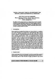
Numerical Results We tested the GPU-based parallel method with a benchmark problem and compared it, in terms of computing velocities, with the serial method. The benchmark problem consists of a 3D wall which gets an initial hit and falls into pieces. Depending on the level of complexity of the simulated scenario, there are 1000, 2000 or 8000 bricks, simulated as rigid bodies. The number of contacts is not constant during the simulation; the amount of contacts can reach very high values during the simulation of the case of 8000 bricks, where the peak number of contacts is in the order of tens of thousands. The friction coefficient between bricks, and between bricks and ground, was set to 0.6. The time step for the entire simulation is h = 0.01s. The simulation time increases linearly with the number of bodies in the model. Moreover, the GPU algorithm is, on average, one order of magnitude faster than the serial algorithm (see Tab.1). The speedup shown in the table could be even more dramatic if one takes into account that those results include also the time spent in performing collision detection and other CPU-intensive computations which are not yet parallelized [41]. In fact, once the CCP solver is implemented in the GPU, the collision detection becomes the bottleneck of the entire process. This motivates future research about the parallelization of collision detection algorithms. In a second example we simulated a bicycle running on uneven pavement, as a case of system with both contacts and bilateral constraints. The vehicle is modeled with 5 rigid bodies, while the driver is built with 13 rigid bodies. All parts can collide with frictional contacts. The total number of scalar bilateral constraints, caused by joints and links, is about one hundred. The contact between the tires and the ground is represented by a custom model which we developed and validated with experimental tests in our labs [42]; this contact model takes into account the elastic deformation of the tyres and can be used for simulating uneven pavements. Figure 9 shows two frames of the simulation, where the effect of misplaced stone slabs can be studied. We noticed that, for simple systems like this one, the speedup coming from GPU parallel processing is not substantial, and the CPU timings would be acceptable anyway. A more appreciable speedup would happen if simulating, for example, many bicycles at once: this is the case, for instance, of genetic optimization or sensitivity analysis.
Conclusions A parallel numerical method has been proposed for the simulation of multibody mechanical systems with frictional contacts and bilateral constraints. The method draws on NVIDIA’s CUDA library and compile-time support to take advantage of the high-performance parallel computation resources available on the GPU. The parallel method is based on an iterative approach that falls within the mathematical framework of measure differential inclusions [24] and is backed by a rigorous convergence analysis [3]. The parallelization of the method required the development of a novel data reduction algorithm, called RMVLA, which maximizes the occupancy of the streaming processors in a critical part of the execution code that requires
15
Figure 9: Example: simulation of a dummy on a bycicle.
fine-grained data synchronization. Preliminary results obtained with the proposed method demonstrate that for large frictional contact problems the time required to solve the cone complementarity problem, which is the computational bottleneck associated with the sequential algorithm, has been drastically reduced. The iterative solver has been implemented in the C++ language in the open source simulation software Chrono::Engine. Future efforts will address the possibility of using clusters of multiple GPU boards on the same host, as well as porting part of the collision detection engine code to the GPU.
Acknowledgment Financial support for the second author is provided in part by National Science Foundation under Grant No. CMMI0700191. A. Tasora and D. Negrut thank the NVIDIA corporation for sponsoring their research programs in the area of high-performance multibody dynamics simulation.
References [1] NVIDIA. CUDA Programming Guide. Available online at http://developer.download.nvidia.com/compute/cuda/1 1/ NVIDIA CUDA Programming Guide 1.1.pdf, 2007. [2] A. Tasora. High performance complementarity solver for non-smooth dynamics. In C. L. Bottasso, P. Masarati, and L. Trainelli, editors, Proceedings of the ECCOMAS Multibody Dynamics Conference, Milano, Italy, 2007. [3] M. Anitescu and A. Tasora. An iterative approach for cone complementarity problems for nonsmooth dynamics. Computational Optimization and Applications, 2008, in press. [4] J. Madsen, N. Pechdimaljian, and D. Negrut. Penalty versus complementarity-based frictional contact of rigid bodies: A CPU time comparison. Technical Report TR-2007-05, Simulation-Based Engineering Lab, University of Wisconsin, Madison, 2007. [5] Bruce R. Donald and Dinesh K. Pai. On the motion of compliantly connected rigid bodies in contact: a system for analyzing designs for assembly. In Proceedings of the Conf. on Robotics and Automation, pages 1756–1762. IEEE, 1990. [6] Peng Song, P. Kraus, Vijay Kumar, and P. Dupont. Analysis of rigid-body dynamic models for simulation of systems with frictional contacts. Journal of Applied Mechanics, 68(1):118–128, 2001. [7] Peng Song, Jong-Shi Pang, and Vijay Kumar. A semi-implicit time-stepping model for frictional compliant contact problems. International Journal of Numerical Methods in Engineering, 60(13):267–279, 2004.
16
[8] Jong-Shi Pang, Vijay Kumar, and Peng Song. Convergence of time-stepping method for initial and boundaryvalue frictional compliant contact problems. SIAM J. Numer. Anal., 43(5):2200–2226, 2005. [9] Jean J. Moreau. Standard inelastic shocks and the dynamics of unilateral constraints. In G. Del Piero and F. Macieri, editors, Unilateral Problems in Structural Analysis, pages 173–221, New York, CISM Courses and Lectures no. 288, Springer–Verlag, 1983. [10] P. Lotstedt. Mechanical systems of rigid bodies subject to unilateral constraints. SIAM Journal of Applied Mathematics, 42(2):281–296, 1982. [11] M. D. P.Monteiro Marques. Differential Inclusions in Nonsmooth Mechanical Problems: Shocks and Dry Friction, volume 9 of Progress in Nonlinear Differential Equations and Their Applications. Birkh¨auser Verlag, Basel, Boston, Berlin, 1993. [12] Jong-Shi Pang and David Stewart. Differential variational inequalities. Mathematical Programming, 113(2):345– 424, 2008. [13] David Baraff. Issues in computing contact forces for non-penetrating rigid bodies. Algorithmica, 10:292–352, 1993. [14] Jong-Shi Pang and Jeffrey C. Trinkle. Complementarity formulations and existence of solutions of dynamic multi-rigid-body contact problems with Coulomb friction. Math. Program., 73(2):199–226, 1996. [15] Jeffrey Trinkle, Jong-Shi Pang, Sandra Sudarsky, and Grace Lo. On dynamic multi-rigid-body contact problems with Coulomb friction. Zeitschrift fur angewandte Mathematik und Mechanik, 77:267–279, 1997. [16] David E. Stewart and Jeffrey C. Trinkle. An implicit time-stepping scheme for rigid-body dynamics with inelastic collisions and Coulomb friction. International Journal for Numerical Methods in Engineering, 39:2673–2691, 1996. [17] Mihai Anitescu and Florian A. Potra. Formulating dynamic multi-rigid-body contact problems with friction as solvable linear complementarity problems. Nonlinear Dynamics, 14:231–247, 1997. [18] Mihai Anitescu, Florian A. Potra, and David Stewart. Time-stepping for three-dimensional rigid-body dynamics. Computer Methods in Applied Mechanics and Engineering, 177:183–197, 1999. [19] David E. Stewart. Rigid-body dynamics with friction and impact. SIAM Review, 42(1):3–39, 2000. [20] Richard W. Cottle and George B. Dantzig. Complementary pivot theory of mathematical programming. Linear Algebra and Its Applications, 1:103–125, 1968. [21] David Baraff. Fast contact force computation for nonpenetrating rigid bodies. In Computer Graphics (Proceedings of SIGGRAPH), pages 23–34, 1994. [22] Mihai Anitescu and Gary D. Hart. A fixed-point iteration approach for multibody dynamics with contact and friction. Mathematical Programming, Series B, 101(1):3–32, 2004. [23] Alessandro Tasora, E. Manconi, and M. Silvestri. Un nuovo metodo del simplesso per il problema di complementarit lineare mista in sistemi multibody con vincoli unilateri. In Proceedings of AIMETA 05, Firenze, Italy, 2005. [24] Mihai Anitescu. Optimization-based simulation of nonsmooth rigid multibody dynamics. Math. Program., 105(1):113–143, 2006. [25] A. A. Shabana. Dynamics of Multibody Systems. Cambridge University Press, third edition, 2005. [26] Mihai Anitescu, James F. Cremer, and Florian A. Potra. Formulating 3d contact dynamics problems. Mechanics of Structures and Machines, 24(4):405–437, 1996.
17
[27] Young J. Kim, Ming C. Lin, and Dinesh Manocha. Deep: Dual-space expansion for estimating penetration depth between convex polytopes. In Proceedings of the 2002 International Conference on Robotics and Automation, volume 1, pages 921–926. Institute for Electrical and Electronics Engineering, 2002. [28] EG Gilbert, DW Johnson, and SS Keerthi. A fast procedure for computing the distance between complex objectsin three-dimensional space. Robotics and Automation, IEEE Journal of [see also IEEE Transactions on Robotics and Automation], 4(2):193–203, 1988. [29] H. Olsson, K.J. Astrom, C.C. de Wit, M. Gafvert, and P. Lischinsky. Friction models and friction compensation. European Journal of Control, 4(3):176–195, 1998. [30] Dimitri P Bertsekas. Nonlinear Programming. Athena Scientific, Belmont, MA, 1995. [31] J. J. Moreau. Unilateral contact and dry friction in finite freedom dynamics. In J. J. Moreau and P. D. Panagiotopoulos, editors, Nonsmooth Mechanics and Applications, pages 1–82, Berlin, Springer-Verlag, 1988. [32] J. S. Pang and D. E. Stewart. Differential variational inequalities. Mathematical Programming, 113:1–80, 2008. [33] David E. Stewart. Convergence of a time-stepping scheme for rigid body dynamics and resolution of Painleve’s problems. Archive Rational Mechanics and Analysis, 145(3):215–260, 1998. [34] Mihai Anitescu and Gary D. Hart. A constraint-stabilized time-stepping approach for rigid multibody dynamics with joints, contact and friction. International Journal for Numerical Methods in Engineering, 60(14):2335– 2371, 2004. [35] M. Flynn. Some computer organizations and their effectiveness. IEEE Trans. Comput., C-21:948, 1972. [36] Leslie Lamport. How to make a multiprocessor computer that correctly executes multiprocess programs. IEEE Trans. on Comput., C-28,9:690–691, 1979. [37] T. Harada. Real-time rigid body simulation on gpus. In Hubert Nguyen, editor, GPU Gems 3, chapter 23. Addison-Wesley, 2007. [38] M. Harris. Mapping computational concepts to gpus. In ACM SIGGRAPH 2005 Proceedings. ACM Press, 2005. [39] J.D. Owens, D. Luebke, N. Govindaraju, M. Harris, J. Krger, A.E. Lefohn, and T. Purcell. A survey of generalpurpose computation on graphics hardware. Computer Graphics Forum, 26-1:80–113, 2007. [40] David Roger, Ulf Assarsson, and Nicolas Holzschuch. Efficient stream reduction on the gpu. In David Kaeli and Miriam Leeser, editors, Workshop on General Purpose Processing on Graphics Processing Units, oct 2007. [41] Physics Simulation Forum. Bullet Physics http://www.bulletphysics.com/Bullet/wordpress/bullet, 2008.
Library.
Available
online
at
[42] M. Crispino, E. Vaghi, and A. Tasora. New method to assess ride safety on uneven element pavements. J. Transp. Engrg., 131:27–36, 2005.
18