EuroCG 2011, Morschach, Switzerland, March 28–30, 2011
A parallel GPU-based algorithm for Delaunay edge-flips Cristobal A. Navarro∗
Nancy Hitschfeld-Kahler†
Abstract The edge-flip technique can be used for transforming any existing triangular mesh into one that satisfies the Delaunay condition. Although several implementations for generating Delaunay triangulations are known, to the best of our knowledge no full parallel GPU-based implementation just dedicated to transform any existent triangulation into a Delaunay triangulation has been reported yet. In the present work, we propose a two-phase iterative GPU-based algorithm, that transforms any 2D planar triangulations and 3D triangular surface meshes into their respective Delaunay form. We tested our method with meshes of different size, and compared it with a sequential CPU-implementation. Based on these results, our algorithm strongly improves the performance with respect to a classic CPU-implementation, thus making it a good candidate for interactive/real-time applications. 1
Introduction
Delaunay triangulations are widely used in several applications because they present good properties that make them useful in 2D and 3D numerical simulations. In the last two decades there has been a considerable amount of work done on computing Delaunay triangulations, from different sequential implementations [9] to recently parallel ones [1], and in particular, GPU-based methods [8, 2]. These works belong to the case when a Delaunay triangulation needs to be computed from a given set of points or from an initial geometry and not from an existing triangulation. On the other hand, transformation methods for existing triangulations have relied on the edge-flip technique first introduced by Lawson [7]. Though the edge-flip technique is simple and the implementation is straightforward, the order of the algorithm is O(n2 ) in the worst case [6, 5] (where n refer the number of points of the triangulation) making its performance potentially slow for millions of triangles. The algorithm of Rong et al. [8] uses the edge-flip operation, but it is implemented on the CPU. Very recently, they improved their method by implementing all the opera∗ Informatics Institute, Austral University, Chile,
[email protected],
[email protected] † Department of Computer Science, FCFM, University of Chile, Chile,
[email protected]
Eliana Scheihing*
tions in parallel [2]. The main differences with our approach are that our algorithm is more straightforward and simple since it is only dedicated to transform any triangulation into a Delaunay triangulation. In addition, Cao’s algorithm uses one thread per triangle and needs to update more complex data structures. Our algorithm uses on thread per-edge and the used data structures are oriented for real-time rendering. There is also another interesting article that describes a parallel GPU-based algorithm designed to generate triangulations for image reconstruction [3]. This algorithm performs edge-flips in parallel according to a function cost that depends on the treated image. If the function is the Delaunay condition, then their algorithm could be used for the purpose of our paper. Their approach is also iterative and uses one thread per edge, but uses different data structures which are oriented to store regions of influence of each edge e and the implementation is done with shaders. The application that motivates our work is the simulation of stem deformations. At each time, the geometry of the triangulation changes and we want to restore the Delaunay condition. Then we want a restoration method capable to perform close to interactive/real-time levels, executing on a desktop workstation. The contribution of this work is a GPUbased method that improves 2D and 3D triangulations. This short paper is organized as follows: Section 2 describes the data structures and Section 3 covers the algorithm and some implementation details. In Section 4 we present results from different tests, to finally discuss and conclude our work in Section 5 . 2
Involved data structures
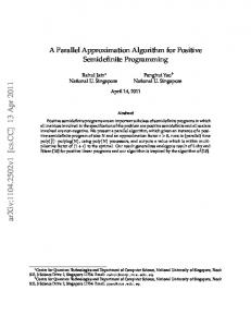
Proper data structures have been defined to represent a triangulation in order to use as efficiently as possible the GPU’s architecture. This representation is inspired on the Dynamic Render Mesh [10]. Figure 1 illustrates the three main components: Vertices, Triangles and Edges. Vertices are handled via the Vertex array where each element contains a position (x, y) or (x, y, z) depending on the dimension used. The Triangles array is a set of indices to the vertex array where each three consecutive indices corresponds to a triangle. Each edge contains a pair of vertex indices v1 , v2 and two references ta , tb to the triangles that share it (for boundary edges, tb remains unused). Both ta and tb contain
27th European Workshop on Computational Geometry, 2011
Surface Mesh S Vertices 0
1
2
n-2
...
n-1
d
3
v2
0
A
B
C
A
B
C
A
B
C
0
1
2
3
4
5
...
...
...
t0
ta tb
v1
e
a
Triangles
Edges
t1
ta tb
v1
v2
1
v1 ...
v2
p-3
T
C
3m-3 3m-2 3m-1
ta tb v1
v2
p-2
Vertices
ta tb
v1
v2
c
0
0
0
Algorithm Overview
Each iteration of the proposed algorithm is divided in two phases: (1) Exclusion & Processing and (2) Repair. The algorithm finishes when all edges fulfill the Delaunay condition. Exclusion & Processing
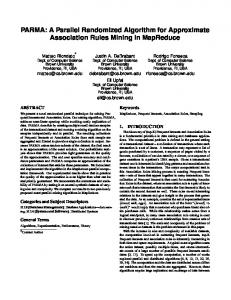
This phase is in charge of a double work: selecting and flipping edges in parallel. It begins by testing each edge against the Delaunay condition. If the condition is fulfilled, then e is Delaunay and the execution thread ends (d = 1), otherwise the thread continues alive (d = 0). Figure 2 shows an example of a small mesh (Se ), where edge e does not satisfy Delaunay condition. In this figure, edge e is the unique internal edge of the mesh, thus the only one to be analyzed (boundary edges are never flipped). This part of the phase adjusts perfectly to the GPU architecture because each edge is an independent problem that can be assigned to a unique thread. Because of neighbor dependency problems, it is not always possible to flip the complete set of d = 0 edges in one iteration because the flip of a given edge e produces a transformation on the triangles (ti , tj ) where this edge belongs to. This transformation affects directly the neighborhood information of the other edges of the triangles that share e, making impossible to flip those while e is being flipped. However, it is
1
2
3
1
3
T1
1 1
2
3
ta
tb
2
3
4
5
Edges
ta 0
a
3
d=1
a pair of indices that point to the exact indices on the Triangles array where this edge can be found. In other words, every edge can access its vertex data directly through v1 , v2 or indirectly via ta , tb . This redundant information becomes useful for consistency checking after an edge flip is performed nearby. The data model was designed so that it could be naturally implemented and integrated with the OpenGL API and at the same time implementable on the CUDA [4] architecture.
1
b
T0
Triangles
p-1
Figure 1: Data structures for mesh rendering/processing.
3.1
1
0
tm-1
ta tb
v2
2
B
...
ta tb
v1
A
0
3
2 T
ta 0
b
1
1
d=1
e
3
ta 2
d=0
d
3
d=1
ta 1
c
2
d=1
Figure 2: On this mesh, e is the only one to flip.
T2
T1
a
b T3
T0 T4
c
T5
Figure 3: The edge subset can either a,c or b,c.
possible to process a subset of edges A that fulfill the following condition: ∀ e1 , e2 ∈ A Te1 ∩Te2 = ∅ where Te = {t ∈ T : e ∈ t} (1) In order to get a proper subset, we propose a parallel exclusion mechanism in which each thread managing a non-Delaunay edge (non-Delaunay edge thread), will be allowed to flip its edge if it is the first one to make a state transition from ”free” to ”taken” (binary flag) on the two triangles that share it. Non-Delaunay edge threads that could not catch their two triangles will find the opportunity to flip their edge on future iterations. Atomic operations are used in this exclusion mechanism in order to avoid any race condition. Figure 3 shows a mesh, where edges a, b, and c need to be flipped but they cannot be processed at the same time. After applying condition 1, the resulting subset can be either {a, c} or {b, c} but a and b will never be selected together, because they share T2 . We design the per thread edge-flip method as an index exchange between the two triangles related to the processed edge e. This transformation can be seen as a rotation of the involved triangles fully independent from the rest of the mesh. The transformation is done on the Triangles array using the information ta and tb stored in the Edges array by following the next steps:
EuroCG 2011, Morschach, Switzerland, March 28–30, 2011
3
• Find the opposite vertex indices u1 and u2 of e in the Triangles array going through ta and tb (Edges array).
T0
Vertexes 0
• Locate the position of the second common vertex index c2 in the Triangles array going through tb .
Triangles
0
2
e
before
T0
0
rotation / flip
0
1
1
3
e T0
T1
2
0
e
T1
1
3
1
2
3
1
ta 1
3
1
0
T1
e
0
2
0
3
2
ta
T1´' 1 3
u2 c2 2
3
4
5
2
0
4
5
2
Figure 4: The edge-flip as a rotation of triangles.
3.2
0
3
a
1
2
3
1
2
3
3
T1 2
4
0
5
ta 0
1
b
ta
tb
0
2
e
ta 2
3
d
ta 1
2
c
Figure 5: Edges marked with a cross are inconsistent.
3.3
tb
e
2
1
1
tb
0
0
2
T0
T0 u1 c1
T0´'
1
3
after
ta
T1
Edges
• Update the values of ta , tb and v1 , v2 related to e in the Edges array.
T1
T0
0
• Exchange data, by copying u1 into Triangles[c2], and u2 into Triangles[c1 ].
3
e
0
• Locate the position of the first common vertex index c1 in the Triangles array going through ta .
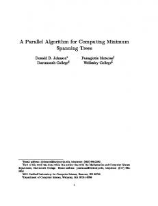
Figure 4 illustrates the case of flipping the edge e from the simple mesh Se (Figure 2) and how the rotation transformation is achieved.
2
Repair
After the parallel edge-flips, consistency problems might appear on the edges nearby a flipped edge. More specifically, some neighbor edges can now store references to triangles whom they do not belong anymore (obsolete ta , tb indices). We say that an edge is inconsistent when its vertex indices obtained through ta , tb differ from the ones stored in v1 and v2 which will always be the correct values. Therefore the edges remain in the same original place but might belong to different triangles ta , tb . In the following simple mesh Se , inconsistent information appears at edges b and d right after flipping e (Figure 5). The detection and fixing of inconsistent edges can also be achieved in parallel; Given an edge e, just compare the vertex indices accessed via ta and tb against v1 and v2 . If the values are different, then search the correct values in the indices of the triangle that were rotated together with ta and tb . The information of the triangles that were rotated together can be stored in the ”Exclusion & Processing” phase as an array R[] where R[ti ] = tj and vice-versa.
Handling problematic cases
During the first phase, there are two cases that we should explain in more detail: (1) the handling of cocircular configurations and (2) if it is possible that a dead-lock might occur for some special cases. We solve the case (1) using an ǫ value. For each edge e, our algorithm uses the simple Delaunay routine that computes the angles λ and γ opposite to e from the triangles that share e and checks the following condition: λ+γ ≤π+ǫ (2) If the condition is true, the edge e fulfills the Delaunay condition. Otherwise is a candidate to be flipped. Since our algorithm does not flip edges whose triangles are defined by co-circular or almost co-circular vertices, each chain of edge-adjacent triangles forming a cycle must have an edge that fulfill the Delaunay condition. This is the smallest edge of the chain. Then, in a chain like this there will be at least one edge than can be flipped: one of the edges that belongs to one of the two triangles that share the smallest edge. We are working on a formal demonstration for this case. 4
Evaluation and results
The hardware used for testing our algorithm consists of an AMD Phenom Quad 2.7GHZ CPU, and two GPUs: Geforce 9800GTX+ and GTX 580. In the following, we call our method MDT (Massive Delaunay Transformations). Tests were done with both 2D and 3D surface triangulations. Figure 6 shows the performance of the algorithm for 2D random generated triangulations of a quad but with different number of triangles. These random triangulations were generated using Blender (subdivision and noise). We also added interactive and real-time time thresholds as good performance reference values. On the
27th European Workshop on Computational Geometry, 2011
9800GTX+, the performance is good for meshes of less than one million triangles but not so good for larger meshes. On the other hand, the GTX 580 performs considerably better as expected, making possible real-time Delaunay transformations on very large triangulations. We have also evaluated MDT with 3D
this case, MDT presents a particular behavior maximizing the number of parallel edge-flips in the middle iterations instead of in the first ones as with the other tests. In the near future, we want to analyze precisely the behavior of our algorithm and to compare its performance with the approaches mentioned above. 6
Acknowledgments
We would like to thank to the anonymous reviewers of the ACM ToG journal and EuroCG2011 for the very useful comments on how to improve our work. References [1] C. Antonopoulos, X. Ding, A. Chernikov, F. Flagojevic, D. Nikolopoulos, and N. Chrisocoides. Multigrain parallel delaunay mesh generation: challenges and opportunities for multithreaded architectures. In ICS ’05 proceedings, pages 367–376, New York, NY, USA, 2005. ACM. Figure 6: Performance on different architectures.
surface triangulations such as the dragon (Stanford Computer Graphics Laboratory), the horse (Cyberware Inc), a moai (Geomview) and the infinite built with our custom tools. Table 1 compares the MDT running on the GTX 580 with a locally built sequential CPU-implementation. Table 1: meshes. Mesh Moai Horse Dragon Infinite
5
Performance comparison of 3D surface # edges 30,000 337,920 1,309,256 4,758,912
CPU-Method [s] 0.867 15.942 0.387 274.1
MDT [s] 0.001 0.012 0.046 0.157
Discussion and Conclusions
Our preliminary results show that MDT can become a practical and useful algorithm for modern dynamic and interactive/real-time applications that need to handle all time a Delaunay mesh. Our GPU-based solution scales very well on newer GPU architectures. The algorithm has also no deep complexity and the data structures are 100% compatible with modern Graphics APIs. MDT is best suited for large meshes composed by at least thousands of edges and most of the times the transformation is achieved with few iterations. We have also tested MDT with one of the worst case meshes for the sequential algorithm [5]. In
[2] T. T. Cao. Computing 2d delaunay triangulation using gpu. Manuscript in preparation, 2010. http://www.comp.nus.edu.sg/ tants/delaunay2D Download.html. [3] M. Cervenansk´ y, Z. T´oth, J. Starinsk´ y, A. Ferko, and M. Sr´amek. Parallel gpu-based datadependent triangulations. Computers & Graphics, 34(2):125–135, 2010. [4] N. Corporation. NVIDIA CUDA Compute Unified Device Architecture - Programming Guide, 2007. [5] H. Edelsbrunner. Geometry and topology for mesh generation (cambridge monographs on applied and computational mathematics), 2001. [6] S. Fortune. A note on delaunay diagonal flips. Pattern Recognition Letters, 14(9):723 – 726, 1993. [7] C. L. Lawson. Transforming triangulations. Discrete Mathematics, 3(4):365 – 372, 1972. [8] G. Rong, T.-S. Tan, T.-T. Cao, and Stephanus. Computing two-dimensional delaunay triangulation using graphics hardware. In I3D ’08 proceedings, pages 89–97, New York, USA, 2008. ACM. [9] J. R. Shewchuk. Triangle: Engineering a 2d quality mesh generator and delaunay triangulator. In First Workshop on Applied Computational Geometry, pages 124–133. ACM, 1996. [10] R. F. Tobler and S. Maierhofer. A Mesh Data Structure for Rendering and Subdivision. Plzen, Czech Republic, 2006.