Int. J. Communications, Network and System Sciences, 2011, 4, 65-76 doi:10.4236/ijcns.2011.41008 Published Online January 2011 (http://www.SciRP.org/journal/ijcns)
A Parametric Colored Petri Net Model of a Switched Network Dmitry A. Zaitsev1, Tatiana R. Shmeleva2 1
2
Department of Information Technology, International Humanitarian University, Odessa, Ukraine Department of Switching Systems, Odessa National Academy of Telecommunications, Odessa, Ukraine E-mail:
[email protected],
[email protected] Received February 26, 2010; revised March 30, 2010; accepted April 2, 2010
Abstract A parametric Colored Petri net model of the switched Ethernet network with the tree-like topology is developed. The model’s structure is the same for any given network and contains fixed number of nodes. The tree-like topology of a definite network is given as the marking of dedicated places. The model represents a network containing workstations, servers, switches, and provides the evaluation of the network response time. Besides topology, the parameters of the model are performances of hardware and software used within the network. Performance evaluation for the network of the railway dispatcher center is implemented. Topics of the steady-stable condition and the optimal choice of hardware are discussed. Keywords: Switched Network, Colored Petri Net, Parametric Model, Network Response Time
1. Introduction The performance evaluation of networks is a significant task especially for real-time applications such as technological processes and traffic control. The complexity of modern networks makes pure analytical methods difficult, for instance, the theory of Markovian processes or the theory of queueing networks. For this purpose, ad hoc simulating systems are developed [1]. These simulating systems are implemented as extensions to programming languages; they are narrowly specialized, relaying strongly on the peculiarities of the application field. Petri nets constitute a universal language for asynchronous systems and processes description. Colored Petri nets [2] implemented in CPN Tools [3] allow the representation of plain colored nets as well as timed and hierarchical nets. Since for the description of elements the programming language CPN ML close to standard ML is used, colored net is a very powerful and convenient tool for various systems specification. The range of projects with CPN Tools application includes telecommunication protocols verification, vehicles control and the planning of military operations. For the investigation of the models’ behavior, a simple simulation of processes’ dynamics is used as well as the construction and Copyright © 2011 SciRes.
analysis of the state space. But the state space construction is useful for such tasks as protocols verification [4]. In performance evaluation, we are interested in the statistical characteristics of models’ behavior. For these purposes CPN Tools proposes a wide range of implemented random functions, for instance, uniformly, exponentially distributed etc. Besides standard facilities for the accumulation of statistical information, special measuring fragments of Petri net model [5] are used. The earlier presented model of switched network [6] was supplied with measuring fragments for the network response time calculation [5] and features for dynamic maintenance of switching tables [7]. The model is constructed of such components as submodels of switch, workstation, server, and measuring workstation. But at the modeling of each new network, we have to assemble the top page out of submodels according to the given topology of network. In the present work we propose the parametric model, which is invariant with respect to topology. An arbitrary topology of the tree-like structure with an arbitrary number of switches and terminal devices is represented as data in the form of the marking for two dedicated places of Petri net. The constructed model was used for performance evaluation of the switched network for a railway dispatcher center supIJCNS
66
D. A. ZAITSEV
plied with GID-Ural [8] CAM software. The remainder of this paper is organized as follows. Section 2 gives an overview of switched Ethernet and presents examples of networks. Section 3 discusses facilities of Colored Petri nets and describes the parametric model of switched Ethernet with the tree-like topology. Section 4 presents the way, in which the parameters of the model may be calculated on the characteristics of hardware and software. Section 5 describes the process of model’s behavior simulation. Section 6 contains the results of performance evaluation for the network of a railway dispatcher center. Section 7 summarizes the paper and gives directions for the application of obtained results.
2. Overview of Switched Networking In the modern epoch of the entirely switched full-duplex Ethernet, the procedures of Carrier Sense Multiply Access with Collision Detection (CSMA/CD), stipulated by the standard IEEE 802.3, are losing their urgency. A microsegmented network [9] uses point-to-point connections only; moreover, the full-duplex mode provides separate channels for independent frames’ transmission in the both directions. Even backpressure procedures are not required if IEEE 802.3x Advanced Flow Control (AFC) is implemented. Each channel of the full-duplex connection may be either free or busy with the transmission of a frame. AFC uses two messages: “suspend transmission” and “resume transmission”. It is implemented in the model with special labels of a channel’s availability. Practically, an entirely switched Ethernet works without collisions providing maximal throughput per each channel equaling 10 Mbps for classical Ethernet IEEE 802.3, 100 Mbps for Fast Ethernet IEEE 802.3u and 1 Gbps for Gigabit Ethernet IEEE 802.3z. We may represent in our models segments, which a few hosts are attached to, for instance, via a hub but it’s a historical necessity only. Such devices as hubs are transparent for switched network and do not have a separate representation in models. According to standards, the frames of useful capacity from 46 to 1500 bytes are transmitted. The frame header contains source and destination addresses and the actual length (or type) of the frame. 6-bytes Media Access Address (MAC) is used. The key element of a network is a switch of frames. As the rule, the majority of modern switches work in store-and-forward mode. At the receiving of a frame the switch stores it in the internal buffer and then forwards the frame to the output port, the target device is attached to. For making the decision regarding the output port number, the switch uses a switching table, Copyright © 2011 SciRes.
ET AL.
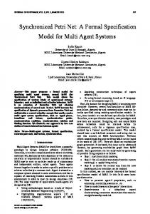
each record of which constitutes a pair: MAC-address and port number. Either dynamic or static tables are used. Recently static tables are applied for networks with high requirements for secrecy only. The static table is entered manually by the administrator of a network. For the construction of dynamic table, the switch only listens to network passively looking for new MAC-addresses. If the destination is unknown, then the switch forwards the frame to all its ports. The records of the table are erased periodically to provide correspondence to the actual structure of the network. In the present work we consider static tables; the influence of dynamic switching on the performance was investigated in [7]. Most widespread topologies of Ethernet are the star shown in Figure 1(a) and the tree shown in Figure 1(b). Star topology is the simplest; it is constituted by single switch (SWI) as well as a stack of switches logically considered as a single switch. To each port of switch only terminal devices are attached. In the tree-like topology, there are connections between switches, which are named by uplinks. In such a network the frame passes a few switches on its way to a target device and in the general case each switch has to know all the MAC-addresses of the network. In this study, we do not consider more complex topologies with duplicated paths between devices because these topologies require modeling the spanning tree procedures stipulated by standard IEEE 802.1 D. To represent realistic traffic we consider an information system, which uses the network. As a rule, for realtime applications such as technological processes control, there is the primary information system. For instance, Figure 1 represents the networks of railway dispatch centers, supplied with CAM system GID-Ural [8]. On the peculiarities of traffic, we distinguish workstations (WS), which generates requests and servers (S), which executes requests and send responses to workstations. We consider only two-way handshake “request-response” in such an interaction but more complicated protocols may be implemented also.
3. Model of Switched Network 3.1. The Overview of Colored Petri Nets Petri net [4] is a bipartite directed graph supplied with dynamic elements named by tokens. The first part of nodes is named by places and is drawn as circles (ellipses), the second part—by transitions drawn as bars. Tokens are represented with dots situated inside places. They move through net modeling processes. First colored Petri nets [2] were suggested to distinguish tokens IJCNS
D. A. ZAITSEV
(a)
ET AL.
67
(b)
Figure 1. Topologies of network. (a) LAN1; (b) LAN2.
as natural numbers. For a finite set of numbers a vivid its representation via colors was possible. CPN Tools [3] uses special kind of colored Petri nets [2] in which tokens are elements of an abstract data type but data types are traditionally named by colors. For description of colors and attributes of places, transitions and arcs CPN ML language is used. The tokens of a place (marking of a place) are represented by multiset; an element belongs to a multiset with a given multiplicity (in a definite number of copies). The multisets are represented by expressions of the following form: k1`e1 ++ k2`e2 ++ … ++kl`el, where ki is the multiplicity of element ei. A place possesses a name, color, initial marking and a current marking. A transition possesses a name, guard and time delay. The input arc of a transition has an inscription defining the pattern for token extraction. The output arc of a transition has an inscription defining the pattern for creation of tokens. The guard constitutes a predicate, which defines the condition for transition’s firing. To model times, special timed multisets of the form e@t are used. It means that token e may be used only after instance t of the model time. In such a notation, @ + d represents the delay with the duration d. Delays may be assigned to transitions as well as to individual tokens. The dynamics of the net consists in moving the tokens as the result of transitions’ firings. Transition is fireable (permitted) if there are tokens in its input places, which satisfies both the inscriptions of arcs and the guard. At firing, transition extracts tokens from its input places and puts new tokens, constructed according to the rules of output arcs’ inscriptions, into its output places. All the output tokens are delayed with the transition’s firing delay. Copyright © 2011 SciRes.
Besides CPN Tools colored Petri nets were implemented in such well known software as Design/CPN, Helena, Miss-RdP and applied successfully in such areas as networking, protocols’ verification, trains’ traffic control, military operations planning, vehicles control, satellite communications and aeronautics.
3.2. Description of Model A parametric colored Petri net model of a switched network is represented in Figures 2-6. The initial parameters correspond to the network structural scheme shown in Figure 1(b). The main page of the model (Figure 2) employs four subpages corresponding to switches SW (Figure 3), workstations WS (Figure 4), servers S (Figure 5), and measuring fragments MEA (Figure 6); declarations are represented in Table 1. In the comparison with the previously presented model [5], the parametric model (Figure 2) is invariant with respect to the networks’ topology. Each page of the model represents all the devices of the same type. For instance, the page SW reflects all the switches of a given network. The solution was obtained on the base of a special tag, which accomplishes merely each element of the model. The tag uniquely defines the segment of a network, which target devices are attached to, with two fields: the number of switch and the number of a switch’s port. The only exception is a segment, which connects a pair of switches. Such a segment has duplicated notation with respect to the upper and lower switches, which it is attached to. The following elements of model are labeled with tags: frames, records of switching table and tokens of a segments’ availability. For a detailed description of the model let us consider the descriptions of colors, variables, constants and funcIJCNS
D. A. ZAITSEV
68
seg 1`avail(1,1)++1`avail(1,2)++1`avail(1,3)++ 1`avail(1,4)++1`avail(2,1)++1`avail(2,2)++ outPorts 1`avail(2,3)++1`avail(2,4)++1`avail(3,1)++ 1`avail(3,2)++1`avail(3,3)++1`avail(3,4)
ET AL.
Workstations WS
1`(1,4,3,1)++1`(3,1,1,4)++ 1`(2,4,3,4)++1`(3,4,2,4) SwichLink swl
swithes SW
1`avail(1,1)++1`avail(1,2)++1`avail(1,3)++ 1`avail(1,4)++1`avail(2,1)++1`avail(2,2)++ 1`avail(2,3)++1`avail(2,4)++1`avail(3,1)++ 1`avail(3,2)++1`avail(3,3)++1`avail(3,4)
1`(1,1,1)++1`(2,2,1)++1`(3,3 1`(4,1,2)++1`(5,2,2)++1`(6,3 1`(7,2,3)++1`(8,3,3)
AttachT swi
inPorts
Servers seg
S
Figure 2. The main page of the parametric model. Table. 1. Descriptions of colors, variables and functions. colset mac = INT; colset portnum = INT; colset swch = INT; colset param = product mac*INT; colset mac2 = product mac*mac timed; colset parambool = product mac*BOOL; colset nfrm = INT; colset sfrm = product mac*nfrm*INT ; colset frm = product mac*mac*nfrm*swch*portnum timed; colset nseg = product swch*portnum; colset seg = union f:frm+avail:nseg timed; colset swi = product mac*portnum*swch; colset swf = product mac*mac*nfrm*swch*portnum timed; colset swf1 = product mac*mac*nfrm*portnum ; colset lswf = list swf1; colset qswf = product swch*mac*lswf; colset frame1 = product mac*mac*nfrm ; colset frame = product mac*mac*nfrm timed; colset proc = INT timed; colset lframe = list frame1;
tions, represented in Table 1. Media Access Control addresses (mac), port numbers (portnum), switch numbers (swch), frames’ sequential numbers (nfrm) are represented with integer type. We abstract from the content of a frame and consider only its header. The frame is represented by color frm, which contains destination and source MAC-addresses, sequential number of request used for the calculation of network response time and the tag with number of switch and number of port. It should be mentioned, that only the destination and source addresses correspond to the real fields of an Ethernet frame’s header, remaining variables are artificially added for the purposes of parametric model’s construction and measurement. Auxiliary types frame, frame1 are used inside submodel of server (S); they do not contain the tag with switch and port number. The only difference beCopyright © 2011 SciRes.
colset qframe = product mac*lframe; colset bufs = product swch*INT; colset swl = product swch*portnum*swch*portnum; var qf:lframe; var src,src1,dst,target,target1, ns: mac; var nsw,sw, sw1, sw2, sw3, swb:swch; var qsw:lswf; var port, inport, outport, p1,p2: portnum; var np:proc; var mf, nf:nfrm; var q, s, r, srt, sr, t1, t2, i: INT; colset dex = int with 100..200; fun Dexec() = dex.ran(); colset nse = int with 10..20; fun Nsend() = nse.ran(); colset Delta = int with 1000..2000; fun Delay() = Delta.ran(); val MaxBuf = 10000; val NumWS = 6; fun cT() = IntInf.toInt(time());
tween them consists in the option timed. For the adequate modeling of frames’ transmission through Ethernet segments, color seg is introduced. It constitutes a union of color frm and unit color avail. Really, if we do not consider collisions, then each channel of a segment may be either available for transmission or busy with the transmission of a frame. In this parametric model all the segments are represented with a pair of places: outPorts, inPorts. These separate places reflect full-duplex mode of data transmission. The places are named with respect to the switch, which the terminal devices are attached to. For instance, place inPorts models transmission of frames from servers and workstations to switches, whereas place outPorts models the transmission of frames from switches to workstations and servers. That is why labels avail bears the tags with number of switch IJCNS
D. A. ZAITSEV 1`(1,1,[])++1`(1,2,[])++1`(1,3,[])++1`(1,4,[])++ 1`(2,1,[])++1`(2,2,[])++1`(2,3,[])++1`(2,4,[])++ 1`(3,1,[])++1`(3,2,[])++1`(3,3,[])++1`(3,4,[]) qbuffer (nsw,ns,qsw)
(nsw,ns,qsw) (nsw,ns,qsw^^[(src,dst,nf,port)])
69
[outport=port,swb=sw1, nsw=sw1] f(src,dst,nf,sw1,outport) put
(nsw,ns,(src,dst,nf,port)::qsw) qswf
ET AL.
@+5 (swb,i-1)
outPorts
f(src,dst,nf,sw,inport)
avail(sw,p1)
(swb,i)
[sw1=sw,p1=inport, sw2=sw3,p2=outport]
1`(1,0)++1`(2,0)++1`(3,0)
[nsw=sw,ns=port ] addbuf
buffersize
@+12
uplink
bufs
(swb,i)
(swb,i+1)
SwichLink
I/O
swl
avail(sw3,outport)
[dst=target,sw1=sw, swb=sw,i