Parametric Petri Net Model for Ethernet Performance and Qos Evaluation Dmitry A. Zaitsev1 and Tatiana R. Shmeleva2 Department of Communication Networks, Odessa National Academy of Telecommunications, Kovalska, 1, Odessa 65029, Ukraine Web1: http://www.geocities.com/zsoftua, E-mail2:
[email protected]
Abstract. Parametric model of switched Ethernet in the form of a colored Petri net is presented. The model is invariant regarding the structure of the network; it has fixed number of nodes for any given tree-like network. Special measuring fragments, which accomplish the model, provide the evaluation of the network throughput and the frame delivery time directly in the process of simulation. The anomaly of Ethernet switches’ mutual blocking has been revealed. Keywords: switched Ethernet, colored Petri net, parametric model, delivery time, throughput, mutual blocking.
1 Introduction At present Ethernet technology dominates the sector of local area networks. Moreover, 1Gb and 10Gb standards allow positioning Ethernet as a universal networking technology, because providers widely apply «Ethernet over DWDM» solutions in backbone networks. Design of effective local and backbone networks requires reliable estimations of throughput and the quality of service. Recently the model driven development of telecommunication networks and devices becomes prospective. It is based on express-evaluations of characteristics obtained in the shortest time for new project decisions that determine the relevance of the present research. Colored Petri Nets [1] and CPN Tools [2] are successfully used for modeling Ethernet [3-5], TCP/IP and MPLS [6], wireless Bluetooth [7] networks. Colored Petri Nets allow not only the modeling of telecommunication networks, but also the estimation of their characteristics via special measuring fragments [4,8] during the process of simulation. The mentioned papers are based mainly on the modular approach to the telecommunication networks models construction: a model of a network is composed of DTE (workstation, server) and DCE (switch, router) submodels, which were built earlier. The essential disadvantages of this approach are the following: the necessity of the model rebuilding for each new structural scheme of the network, great number of used Petri net elements that considerably delay the processes of models construction and analysis. The parametric model of switched Ethernet presented in [5] has a fixed structure for an arbitrary tree-like network; its elements are switches, workstations and servers. The definite structure of a network is an input in the form of packed matrices as the marking of corresponding Petri net places. However, in [5] only the principles of a parametric Petri models construction were studied and the questions about the evaluation of the modeled networks characteristics were not considered.
The goal of the present work is constructing the measuring fragments for parametric model of switched Ethernet for the evaluation of throughput (traffic), the quality of service (frame delivery time), the size of the switches internal buffers. Moreover, for the confirmation of the built models adequacy, the technique for the mentioned characteristics measuring on real-life networks was developed.
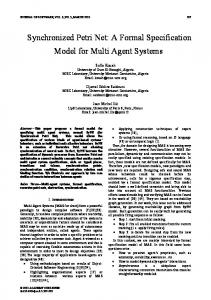
2 Parametric Model of Switched Ethernet The model presented in [5] was refined in the following way: the expressions in the transitions guards were simplified via variables superposition; the limitations of the switches internal buffer size were added; the places, which describe the dump of frames for the following calculation of characteristics, were added. The model is represented in Fig. 1; the declarations of colors (color), variables (var) and functions (fun) used in the model and measuring fragments are represented in Fig. 2. The peculiarity of the parametric model is the special tags added to frames, which contain switch and port numbers and provide the frames reentrance. The model has a fixed structure and contains 14 places and 8 transitions of Petri net for an arbitrary tree-like structure. The components of the model are switches, workstations and servers. The left part of Petri net models all the Ethernet switches (the names of the elements names do not have any suffix), the right upper part – all the workstations (the names of the elements have WS suffix), the left lower part – all the servers (the names of the elements have S suffix); the pair of places inPorts, outPorts model all segments. Names “in/out” are chosen with respect to the switches; they model the full-duplex mode of work. Additional places received, sent model the frames dump by DTE, places inSW, outSW model the frames dump by switches. Additional names rcvd, snd, inSWITCH, outSWITCH are used for the connection with model pages, which calculate characteristics described in the next section. A definite structure of modeled network is specified by the marking of places swtab, SwichLink, Attach. The place swtab contains the switching tables of all the switches. The switching tables are represented by corteges swi (destination address, port, switch). The place SwichLink describes the connections of switches (uplinks), which are represented by corteges swl (switch1, port1, switch2, port2). The place Attach describes the DTE connection, which is represented by corteges swi (address, port, switch). In Fig. 1 the marking of the places corresponds to the Railway dispatcher center LAN represented in Fig. 3.
outSW outSWITCH
received rcvd mac2s (src,dst,nf,cT())
buflimit
(sw,bcur)
avail(sw,p) 1`avail(1,1)++1`avail(1,2)++1`avail(1,3)++ 1`avail(1,4)++1`avail(2,1)++1`avail(2,2)++ 1`avail(2,3)++1`avail(2,4)++1`avail(3,1)++ 1`avail(3,2)++1`avail(3,3)++1`avail(3,4) (src,dst,p,sw,nf)
buffer
put
swf
@+12 (sw,bcur)
(sw,bcur-1)
receiveWS
ownWS mac
@+4
f(src,dst,p,sw,nf)
(dst,p,sw)
SwichLink
outPorts
avail(sw,p)
(sw1,p1,sw2,p2) (sw,bcur)
sendWS
uplink
(src,dst,nf+1)@+Delay()
(src,dst,p2,sw,nf)
avail(sw2,p2)
@+dSr
f(src,dst,p2,sw2,nf)
ownS mac
requestS frame
[bcur