Petri Net (PN) diagram is generated from the UML models to simulate the behavior of an agent. Because Petri Nets (PNs) are formal models, their analysis ...
American Journal of Applied Sciences, 2012, 9 (11), 1876-1883
ISSN 1546-9239 ©2012 Science Publication doi:10.3844/ajassp.2012.1876.1883 Published Online 9 (11) 2012 (http://www.thescipub.com/ajas.toc)
A PETRI NET BASED AGENT BEHAVIORAL TESTING 1
Zina Houhamdi and 2Belkacem Athamena 1
Department of Software Engineering, College of Engineering and Information Technology, 2 Department of Management Information Systems, College of Business Administration, Al Ain University of Science and Technology, Al Ain, Abu Dhabi, UAE Received 2012-06-13, Revised 2012-09-08; Accepted 2012-09-10
ABSTRACT In Multi-Agent System (MAS), developers concentrate on creating design models and evolving them, from higher level models to lower level models, in several steps. Considerable part of MAS implementations is automatically produced from the design models. If a design model contains faults, they are passed to the generated implementations. Practical model validation techniques are required to discover and delete faults in abstract design models. We introduce a formal approach for agent design testing. It specifies a testing process that complements Multi-agent Systems Engineering (MaSE) methodology and strengthens the mutual relationship between UML and MAS. Besides, it defines a structured and comprehensive testing process for engineering software agents at the design level by providing a systematic way of converting the MAS design models to UML design diagram. Petri Net (PN) diagram is generated from the UML models to simulate the behavior of an agent. Because Petri Nets (PNs) are formal models, their analysis techniques can be applied to automatic agent behavioral testing. Keywords: Multi-Agent System (MAS), Petri Net (PN), Software Testing, Multi-Agent Systems Engineering (MaSE), Task Diagram, Activity Diagram, Petri Net enough to assess agent’s autonomous behaviors and build confidence in them (Houhamdi and Athamena, 2011a). On the other hand as model-based software development discipline such as the Unified Modeling Languages (UML) have previously obtained reputation, more and more UML-based design, analysis, testing and monitoring tools have been developed. UML consist of a set of models that can provide different levels of capacity and accuracy for modeling objects and then can be employed to fulfill different requirements in real word applications. However, a usual AOSE methodology such as MaSE (Bergenti et al., 2004; DeLoach, 2009) presents diverse new abstractions and design concepts to software development in comparison with regular model-based approaches such as UML. This makes the deployment of UML-based testing tools for checking the internal behavior of MAS difficult and sometimes impossible. Thereby, transformation models that fill the gap between the AOSE design/ analysis artifacts and the UML-based testing and supervising tools can be very helpful. The transformation models can assist MAS engineers to use
1. INTRODUCTION The growing requests for Multi-Agent Systems (MAS) in the software application have led to the elaboration of various Agent Oriented Software Engineering (AOSE) methodologies to support the development of agent-based applications. The agentbased applications are composed of autonomous and intelligent software (agents) that can communicate and exchange information to solve problems collaboratively (Houhamdi, 2011). Because the agents’ interactions in MAS context can conceivably lead to behavioral faults like deadlock, the MAS behavior should be tested and supervised facing the unwanted behaviors (usually known as emergent behavior) before introducing it to the main stream of commercial software development (Nguyen et al., 2010). The AOSE methodologies usually do not cover monitoring and testing (Huget and Demazeau, 2004). As a consequence, testing software agents search for new testing techniques dealing with their particular nature. The techniques require to be efficient and good
Corresponding Author: Zina Houhamdi, Department of Software Engineering, College of Engineering and Information Technology, Al Ain University of Science and Technology, Al Ain, Abu Dhabi, UAE Science Publications
1876
AJAS
Zina Houhamdi and Belkacem Athamena / American Journal of Applied Sciences 9 (11) (2012) 1876-1883
the UML-based testing and supervising tools to test and check the internal behavior of the developed MAS before delivering it as commercial software. In this study, we propose a formal approach for agent testing process by using PN model. This approach exploits the link between AOSE, UML and PN. We describe the proposed approach with reference to MaSE software development methodology and consider MAS as the target implementation technology. The MaSE design/analysis artifacts should be converted to the standard UML diagrams which will be used for constructing PN diagrams in order to achieve agent formal testing. Then, the PN based analysis techniques can be applied to software testing. The rest of the study recalls basic elements of the MaSE methodology and introduces related works.
to agents. Each agent is associated with at least one role. The conversations among agent classes are also specified using the protocols defined in the analysis phase (the links among tasks within the role model).
1.1. MaSE
1.7. Assembling Agent
The Multi-agent Systems Engineering methodology (MaSE) is a methodology for building practical agent systems that defines MAS in terms of agent classes and their organization (DeLocah, 2004). There are two basic phases in MaSE: analysis and design. The first phase, Analysis, includes three steps.
In this step, the agent’s internal architecture is specified. One can use its own architecture to build an agent (e.g., Belief-Desire-Intention) or convert the tasks from the previous step into components. The agent architecture consists of the components and the relationships among them.
1.2. Capturing Goals
1.8. System Design
In this step the system goals are elaborated and specified from the system viewpoint and not from the user viewpoint. A goal is an abstraction of a set of functional requirements. This stage comprises two sub-stages: identifying the goals and structuring them in a hierarchy.
This step is aim at presenting the physical system architecture and the distribution of the various agent classes’ instances within that architecture. According to the results of evaluation in (Elamy and Far, 2008) the MaSE was ranked first in three of the proposed dimensions, i.e., modeling-related attributes, application-related attributes and user perception attributes. Eventually, MaSE was ranked first in overall ranking of evaluated AOSE methodologies.
1.6. Constructing Conversations In this step, the designer defines the coordination protocols between agent couples. In particular, two communication class diagrams are defined for each conversation. One diagram specifies the initiator behavior during that conversation and the second one specifies the responder behavior during that conversation. The communication class diagram is designed using a finite state automaton.
1.3. Applying Use Cases In this step the system use cases are specified. It is split into two sub-stages: the creation of use cases and the creation of the sequence diagrams. A use case is a set of interactions which describes the general system behavior (what the system should do). The transformation from the use cases specification to sequence diagrams is straightforward; each entity becomes a role and information passing becomes an event (or a message).
1.9. UML The Unified Modeling Language (UML) is an OMG standard language for modeling object-oriented systems. UML is used by developers to describe designs at different levels of abstraction, from conceptual to detailed design (Bergenti et al., 2004). There are several advantages gained from using UML OMG, 2007:
1.4. Refining Roles In this step the system functional decomposition is determined by producing a set of roles and their associated tasks. This stage consists of two sub-stages: building the role diagram and specifying the tasks' behavior. The inputs for this stage are the goals determined in the 1st stage and the sequence diagrams created in the 2nd stage. In the Design phase, we transform the analysis models into constructs useful for actually implementing the MAS. The Design phase has four steps.
•
1.5. Creating Agent Classes
UML has 14 types of diagrams divided into two categories. Seven diagram types represent structural information and the other seven represent general
• •
In this step, the overall MAS architecture is determined. Agent classes are created by assigning roles Science Publications
1877
Firstly, UML includes a set of models that can provide different levels of capacity and accuracy for modeling objects and thus can be used to satisfy various needs in real word applications Secondly, UML has emerged as the de-facto industry standard for software modeling Thirdly, UML provides high level information that illustrates the internal behavior of the system, which can be used efficiently and effectively in testing
AJAS
Zina Houhamdi and Belkacem Athamena / American Journal of Applied Sciences 9 (11) (2012) 1876-1883
automatically system properties like reachability, boundedness, liveness, persistence and fairness (Oliveira et al., 2007). The advantages of automated testing are reliability, cost reduction and fastness. The remainder of the study is organized as follows. Section 2 discusses the proposed approach; a PN based agent testing process. An illustrative example is presented in section 3. Similar works are listed in section 4. Finally, section 5 concludes our work.
types of behavior, including four that represent different aspects of interactions. When using UML in the software testing process, we will pay a special attention to the diagrams in the Behavioral Elements package. This is because most of the activities in software testing attempt to detect defects that appear during the software execution and these defects are generally dynamic (behavioral) in nature (DeLocah, 2004). Nevertheless, there are cases where the behavioral information will need to be augmented with static information. UML design models are typically evaluated using walkthroughs, inspections and other informal types of design review techniques that are largely manual. These techniques are not effective when applied to UML design models of large or complex systems. Reviewers need to manually track and relate a large number of concepts across various diagrams and the manual tasks can rapidly become wearisome and fault-prone for complex design which is the case in MAS (Houhamdi and Athamena, 2011b). Thus, providing a formal approach for MAS design testing will be considerably helpful.
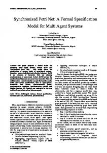
2. MATERIALS AND METHODS We have already proposed a PN based approach for the whole MAS behavior testing (Athamena and Houhamdi, 2012). In this study, we will focus on proposing a PN based approach for a single agent behavior testing. In section 2, a conversion model is presented for adopting the MAS design/analysis models created based on MaSE methodology into standard UML 2.0 models and then the UML models are transformed to PNs for formal testing. The proposed approach overview is shown in Fig. 1. The approach is divided into two main modules.
1.10. Petri Net
2.1. Module 1. Constructing Agent Behavioral Model
PNs are a formal language for describing and studying systems that are characterized as concurrent, asynchronous, distributed, parallel, nondeterministic and/or stochastic. As a graphical tool, PNs can be used as a visual communication support similar to flow charts, block diagrams. In addition, tokens are used in these nets to simulate the dynamic and concurrent activities of systems. PN consists of places, transitions and arcs: •
•
•
A conversion model is proposed to transform the MaSE design/analysis artifacts into standard UML 2.0 models. This module uses the MaSE models as input and constructs the Agent behavioral models based on UML models.
2.2. Module 2. Converting Behavioral Model to PN A conversion model is proposed to transform the UML 2.0 models into PNs model. This module uses the UML models as input and constructs the agent behavioral model based on PN model.
Transitions are active components. They model activities which can occur, thus changing the state of the system. Transitions are only allowed to fire if they are enabled, which means that all the preconditions for the activity have been fulfilled Places are tokens’ holders. The current state of the system being modeled is called marking which is given by the number and type (if the tokens are distinguishable by type) of tokens in each place Arcs are of two types: Input and output. Input arcs start from a places and ends at a transitions, while output arcs start at a transition and end at a place
When the transition fires, it removes tokens from its input places and adds some at all of its output places. The number of tokens removed/added depends on the cardinality of each arc. The use of PNs leads to a mathematical description of the system structure that can then be investigated analytically. It is possible to set up state or algebraic equations and other mathematical models governing the behavior of systems. PNs can be used for analyzing Science Publications
Fig. 1. Agent design testing flow chart 1878
AJAS
Zina Houhamdi and Belkacem Athamena / American Journal of Applied Sciences 9 (11) (2012) 1876-1883
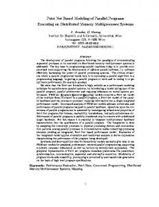
Fig. 2. MAS meta-model Table 1. Concepts mapping from activity diagram to PN Concepts Activity diagram Scenario representation activity Entities Swimlane/Partition Function and action performed Action Scenario starts and stop Initial node and final node Alternative scenario Concurrency flow Alternative flow Sequence flow Alternative merge Synchronizing concurrent flow Objects
Sub activity Fork node Decision node Activity edge Merge node Join node Object node
how a goal is achieved by a specific agent task and can be represented by PN. A proposed approach for transforming the agent behavior from task diagram to UML activity diagrams is introduced in section 2.3. More details on deriving PN from UML activity diagrams are provided in section 2.4. In MaSE, a task is a structured set of activities and communications, represented by a state machine diagram which consists of states and transitions. State represents a stage in the agent behavior pattern and includes the internal processing of the agent and transition is a progression from one state to another and will be triggered by an event that is either internal or external to the agent. Thus, transitions allow communication between tasks. A transition in MaSE task diagram uses the syntax of trigger (guard)/transmission, interpreted as if an event trigger is received and the condition guard holds, then the message transmission is sent. In this transition notation all items are optional. In Tasks diagram, states may include activities that represent internal reasoning, performing actions via agent, or reading a percept from sensors. Several activities can be in a unique state and are executed in an uninterruptable succession. Once in a state, the task remains there until the activity sequence is completed.
Table 2. Translation rules of activity edges to PNs Source node(s) Target node(s) of edge of edge Transformation Initial node or Action Node or Arc Decision node or Fork Node or Merge node or Join Node Object node Initial node or Decision node or Arc, dummy Decision node or Merge node or Transition and Merge node or Object node or dummy Arc Object node Final node Action node or Action node or Arc, dummy Fork node or Fork node or place and Join node Join node dummy Arc Decision node or Action node or Merge node or Fork node or Object node or Join node Final node Arc
2.3 Constructing Agent Behavioral Model Figure 2 presents an illustrative meta-model for the MAS. In this figure, each MAS consists of several agents. Agents are the building blocks used to define MAS classes and capture system goals during the design phase. With each role is associated several tasks and each task can be presented by a MaSE task diagram (Bergenti et al., 2004). Each MaSE task diagram can be converted to a UML activity diagram which describes Science Publications
Petri net CP Net Will be modeled as a place Transition A place without any incoming edge and a place without any outgoing edge, respectively Subpage Will be modeled as a transition Will be modeled as a place Arc Will be modeled as a place Will be modeled as a transition Will be modeled as a place
1879
AJAS
Zina Houhamdi and Belkacem Athamena / American Journal of Applied Sciences 9 (11) (2012) 1876-1883
Consequently, the activities within tasks diagrams, their execution constraints and their sequences can be extracted from the states and the corresponding activity diagram for a MaSE task diagram can be produced. In addition, because the protocol transition in MaSE task diagram uses the syntax of trigger (guard)/transmission and the trigger and transmission are restricted to send and receive messages (DeLocah, 2004), trigger should be considered as the last activity of the source state and transmission should be considered as the first activity of destination state. In this way, the trigger message is considered as the activity that after completing its execution the control flow will be transferred to the first activity of destination state (transmission).
The table below (Table 1) explains the mapping of concepts of Activity Diagrams to PNs. The Translation rules of activity edges to PNs are presented in the following table (Table 2). Maqbool (2005) propose different possibilities of Activity Diagrams simplifications before the transformation to PNs to reduce the number of transitions, places and arcs in the resulting net.
3. RESULTS An example of a task diagram describing the locate victim task is shown in Fig. 3 (DeLoach et al., 2002). Actions within each state are executed sequentially and are written as functions. Locate victim is a reactive task, which means that it is initiated whenever a search (area) message is received from the find area to Search task. After the task receives a search area message, it plans a route to obtain to the area and then goes about executing the route. If route execution fails, the task re-plans the route and updates the map.
2.4 Deriving PN from Activity Diagram As already mentioned, PNs is a formal language which can be used for Design validation by simulating/executing the system models. The section 2.4. explain how the concepts introduced in UML 2.0 Activity Diagrams can be mapped to PNs. In this conversion, the proposed idea by (Maqbool, 2005) was used.
Fig. 3. Locate victim task diagram Science Publications
1880
AJAS
Zina Houhamdi and Belkacem Athamena / American Journal of Applied Sciences 9 (11) (2012) 1876-1883
Fig. 5. Associated PN
According to the proposed algorithm, the equivalent PN of activity diagram (Fig. 4) is shown in Fig. 5.
4. DISCUSSION The rest of the section 4 surveys recent and active work on testing software agents. Luck and Gomez-Sanz (2009) presented advances in testing and debugging used in the INGENIAS methodology (Pavon et al., 2005). The meta-model of INGENIAS has been extended to introduce testing declaration, i.e., tests and test packages. JUnit-based test case and suite skeletons can be generated and it is the developer’s task to modify them as needed. The study also provided facilities to access mental states of individual agents to check them at runtime. Coelho et al. (2006) proposed a framework for unit testing of MAS based on the use of mock agents. Even
Fig. 4. Corresponding activity diagram
When the robot gets to its area, it scans the area for victims. If one is found, it notifies an organizer role. The robot then moves to another area and continues searching. If no victims are found, the robot moves to another area and scans there. Once it has scanned its area, it sends the find area to search task a complete message and terminates. Notice that tasks actually define a plan on how to locate victims. Figure 3 shows task diagram for locate victim and Fig. 4 give its corresponding activity diagram. Science Publications
1881
AJAS
Zina Houhamdi and Belkacem Athamena / American Journal of Applied Sciences 9 (11) (2012) 1876-1883
•
though they called it unit testing but their work focused on testing roles of agents at agent level. Mock agents that simulate real agents in communicating with the agent under test were implemented manually; each corresponds to one agent role. Sharing the inspiration from JUnit (Gamma and Beck, 2000) with Coelho et al. (2006) and Tiryaki et al. (2007) proposed a test-driven MAS development approach that supported iterative and incremental MAS construction. A testing framework called SUnit, which was built on top of JUnit and Seagent (Dikenelli et al., 2005) was developed to support the approach. The framework allows writing tests for agent behaviors and interactions between agents. Lam and Barber (2005) proposed a semi-automated process for comprehending software agent behaviors. The approach imitates what a human user (can be a tester) does in software comprehension: Building and refining a knowledge base about the behaviors of agents and using it to verify and explain behaviors of agents at runtime. Although the study did not deal with other problems in testing, the way it evaluates agent behaviors is interesting and relevant for testing software agents. Nunez et al. (2005) introduced a formal framework to specify the behavior of autonomous ecommerce agents. The desired behaviors of the agents under test are presented by means of a new formalism, called utility state machine that embodies users’ preferences in its states. Two testing methodologies were proposed to check whether an implementation of a specified agent behaves as expected (i.e., conformance testing). In their active testing approach, they used for each agent under test a test (a special agent) that takes the formal specification of the agent to facilitate it to reach a specific state. The operational trace of the agent is then compared to the specification in order to detect faults. On the other hand, the authors also proposed to use passive testing in which the agents under test were observed only, not stimulated like in active testing. Invalid traces, if any, are then identified thanks to the formal specifications of the agents. In this study, we have proposed a model checking approach for agent behavioral testing using the MaSE methodology design/analysis artifacts. These artifacts (more precisely task diagram) are transformed into the standard UML 2.0 models (exactly into activity diagram) using a proposed conversion model. Then, these activity diagrams are used to generate an equivalent PN. Finally, the analysis techniques of PN can be applied to automatic MAS testing. Specifically, the proposed approach contributes to the existing AOSE methodologies by providing: •
•
5. CONCLUSION Testing and monitoring MAS to eliminate the risk of unwanted emergent behaviors is an important precondition for introducing MAS to the main stream of commercial software. Most of the exiting testing techniques for MAS have addressed the MAS verification aspects. This study describes a systematic and automatable approach to test agent design models using PN theory. The MAS design models, consisting of agent task diagrams built based on the MaSE methodology, are converted to UML activity diagrams which are used to generate an equivalent PN diagram. Since PNs are formal language, they are used for automatic checking of agent’ behavioral properties thereby eliminating human errors.
REFERENCES Athamena, B. and Z. Houhamdi, 2012. A petri net based multi-agent system behavioral testing. Modern Applied Sci., 6: 46-57. DOI: 10.5539/mas.v6n3p46 Bergenti, F., M.P. Gleizes and F. Zambonelli, 2004. Methodologies and Software Engineering for Agent Systems: The Agent-oriented Software Engineering Handbook. 1st Edn., Springer, Boston, ISBN-10: 1402080573, pp: 536. Coelho, R., U. Kulesza, A. Staa and C. Lucena, 2006. Unit testing in multi-agent systems using mock agents and aspects. Proceedings of the International Workshop on Software Engineering for Large-Scale Multi-Agent Systems, May 20-28, ACM Press, New York, pp: 83-90. DOI: 10.1145/1138063.1138079 DeLoach, S., E.T. Matson and Y. Li, 2002. Applying agent oriented software engineering to cooperative robotics. Proceedings of the 15th International FLAIRS Conferences Pensacolo Florida, (PF’ 02), AAAI Press, pp: 532-6350. DeLoach, S.A., 2009. Moving multi-agent systems from research to practice. Int. J. Agent-Oriented Software Eng., 3: 378-382. DOI: 10.1504/IJAOSE.2009.025315
A complete and comprehensive testing process for MAS Science Publications
Reducing/removing side effects in test execution and monitoring because introducing new entities in the system, e.g., mock agents tester agents and monitoring agent as in many approaches, can influence the behavior of the agents under test and the performance of the system as a whole. Testing emergent properties at macroscopic design level
1882
AJAS
Zina Houhamdi and Belkacem Athamena / American Journal of Applied Sciences 9 (11) (2012) 1876-1883
Luck, M., and J.J. Gomez-Sanz, 2009. Agent-Oriented Software Engineering. 1st Edn., Springer-Verlag Berlin, Heidelberg, Berlin, ISBN-10: 3642013376, pp: 289. Maqbool, S., 2005. Transformation of a core scenario model and activity diagrams into Petri nets. M.Sc Thesis, University of Ottawa, Ontario, Canada. Nguyen, C., A. Perini and P. Tonella, 2010. Goaloriented testing for MASs. Int. J. Agent-Oriented Software Eng., 4: 79-109. DOI: 10.1504/IJAOSE.2010.029810 Nunez, M., I. Rodriguez and F. Rubio, 2005. Specification and testing of autonomous agents in ecommerce systems. Software Test. Verific. Reliab., 15: 211-233. DOI: 10.1002/stvr.v15:4 Oliveira, E., H. Almeida and L. Silva, 2007. Formal modelling and verification of a component model using coloured petri nets and model checking. Proceedings of the 1st Symposium Applied Computing, (SAC’ 07), ACM Press, New York, USA., pp: 1427-1431. DOI: 10.1145/1244002.1244309 Pavon, J., J. Gomez-Sanz and R. Fuentes-Fernandez, 2005. The INGENIAS Methodology and Tools. In: Agent Oriented Methodologies, Fuentes, R., (Ed.)., Universidad Complutense de Madrid, Spain, pp: 236-276. Tiryaki, A.M., S. Oztuna, O. Dikenelli and R.C. Erdur, 2007. SUNIT: A unit testing framework for test driven development of multi-agent systems. AgentOriented Software Eng., 4405: 156-173.
DeLocah, S.A., 2004. The MaSE Methodology. In: Methodologies and Software Engineering for Agent Systems: The Agent-oriented Software Engineering Handbook, Bergenti, F., M.P. Gleizes and F. Zambonelli, (Eds.)., Springer, Boston, ISBN-10: 1402080573, pp: 107-127. Dikenelli, O., R.C. Erdur and O. Gumus, 2005. Seagent: A platform for developing semantic web based multi agent systems. Proceedings of the 4th International Joint Conference on Autonomous Agents and MultiAgent Systems, (AAMAS’ 05), ACM Press, New York, pp: 1271-1272. DOI: 10.1145/1082473.1082728 Elamy, A. and B. Far, 2008. A statistical approach for evaluating and assembling agent oriented software engineering methodologies. Agent-Oriented Inform. Syst., 6: 105-122. Gamma, E. and K. Beck, 2000. JUnit: A regression testing framework. CiteULike. Houhamdi, Z. and B. Athamena, 2011a. Structured integration test suite generation process for multiagent system. J. Comput. Sci., 7: 690-697. DOI: 10.3844/jcssp.2011.690.697 Houhamdi, Z. and B. Athamena, 2011b. Structured system test suite generation process for multi-agent system. Int. J. Comput. Sci. Eng., 3: 1681-1688. Houhamdi, Z., 2011. Multi-agent system testing: A survey. Int. J. Adv. Comput. Sci. Appli., 2: 135-141. Huget, M. and Y. Demazeau, 2004. Evaluating multiagent systems: A record/replay approach. Proceedings of the IEEE/WIC/ACM International Conference on Intelligent Agent Technology, Sept. 20-24, IEEE Xplore Press, pp: 536-539. DOI: 10.1109/IAT.2004.1343013 Lam, D.N. and K.S. Barber, 2005. Debugging agent behavior in an implemented agent system. Program. Multi-Agent Syst., 3346: 104-125.
Science Publications
1883
AJAS