www.ccsenet.org/mas
Modern Applied Science
Vol. 6, No. 3; March 2012
A Petri Net Based Multi-Agent System Behavioral Testing Belkacem Athamena (Corresponding author) MIS Department, College of Business Administration Al Ain University of Science and Technology PO box 64141, Al Ain, Abu Dhabi, UAE E-mail:
[email protected] Zina Houhamdi Software Engineering Department, College of Engineering and IT Al Ain University of Science and Technology PO box 64141, Al Ain, Abu Dhabi, UAE E-mail:
[email protected] Received: December 29, 2011 doi:10.5539/mas.v6n3p46
Accepted: January 18, 2012
Published: March 1, 2012
URL: http://dx.doi.org/10.5539/mas.v6n3p46
Abstract In Multi-Agent System (MAS), developers concentrate on creating design models and evolving them, from higher level models to lower level models, in several steps. Considerable part of MAS implementations is automatically produced from the design models. If a design model contains faults, they are passed to the generated implementations. Practical model validation techniques are required to discover and delete faults in abstract design models. In this paper, we introduce a formal approach for MAS design testing. It specifies a testing process that complements Multi-agent Systems Engineering (MaSE) methodology and strengthens the mutual relationship between UML and MAS. Besides, it defines a structured and comprehensive testing process for engineering software agents at the design level by providing a systematic way of converting the MAS design models to UML design diagram. Then a Petri Net (PN) diagram is generated from the UML models to simulate the behavior of the MAS system. Finally, because Petri Nets (PNs) are formal models, their analysis techniques can be applied to automatic MAS behavioral testing. Keywords: Multi-agent System, Software testing, MaSE, Sequence diagram, Petri net 1. Introduction MAS are increasingly taking over operations and controls in enterprise management, automated vehicles, and financing systems, assurances that these complex systems operate properly need to be given to their owners and their users (Nguyen, et al., 2010). This calls for an investigation of suitable software engineering frameworks, including requirements engineering, architecture, and testing techniques, to provide adequate software development processes and supporting tools. There are several reasons for the increase of the difficulty degree of multi-agent systems testing: Increased complexity, since there are several distributed processes that run autonomously and concurrently; Amount of data, since systems can be made up by thousands of agents, each owning its own data; Irreproducibility effect, which means that it is not ensured that two executions of the systems will lead to the same state, even if the same input is used. As a consequence, looking for a particular error can be difficult if it is not possible to reproduce it each time (Huget & Demazeau, 2004). As a result, testing software agents seeks for new testing techniques dealing with their peculiar nature. The techniques need to be effective and adequate to evaluate agent's autonomous behaviors and build confidence in them (Houhamdi & Athamena, 2011a; Athamena & Houhamdi, 2012).
46
ISSN 1913-1844
E-ISSN 1913-1852
www.ccsenet.org/mas
Modern Applied Science
Vol. 6, No. 3; March 2012
Several Agent Oriented Software Engineering (AOSE) methodologies have been proposed (Houhamdi, 2011). These methodologies have brought number of new abstractions and design/development concepts to software development. The model-based software development practices are becoming more popular (OMG, 2007) and in consequence more and more MAS are developed using these practices such as MaSE (DeLoach, 2004; DeLoach, 2009). Therefore, the MAS engineers can remove the deadlock risks in MAS development by using these model-based testing techniques. However, The AOSE methodologies usually do not cover monitoring and testing. In comparison with regular model-based approaches such as UML which are equipped with a rich set of model based testing technique, a typical AOSE methodology introduces several new design concepts and abstractions to software development. This makes the use of UML-based testing tools for checking the MAS internal behavior harder and sometimes impossible. Thereby, transformation models that fill the gap between the AOSE design/analysis concepts and the UML-based testing tools can be very helpful. The transformation models can facilitate the MAS engineers’ tasks by using the UML-based testing tools to check the MAS internal behavior before deploying it as commercial software. In this paper, we propose a formal approach for MAS testing process by using PN model. This approach exploits the link between AOSE, UML and PN. We describe the proposed approach with reference to MaSE software development methodology and consider MAS as the target implementation technology. The MaSE design/analysis artifacts should be converted to the standard UML diagrams which will be used for constructing PN diagrams in order to achieve MAS formal testing. Then, the PN based analysis techniques can be applied to software testing. The remainder of the paper is organized as follows. Section 2 recalls basic elements of the MaSE methodology and introduces related works. Section 3 discusses the proposed approach; a PN based MAS testing process. An illustrative example is used. Similar works are presented in section 4. Finally, section 5 concludes our work and discusses future research directions. 2. Background and Related Works 2.1 MaSE The Multi-agent Systems Engineering methodology (MaSE) is a methodology for building practical agent systems that defines MAS in terms of agent classes and their organization (De Loach, 2004). There are two basic phases in MaSE: analysis and design. The first phase, Analysis, includes three steps: Capturing goals: In this step the system goals are elaborated and specified from the system viewpoint and not from the user viewpoint. A goal is an abstraction of a set of functional requirements. This stage comprises two sub-stages: identifying the goals and structuring them in a hierarchy. Applying use cases: In this step the system use cases are specified. It is split into two sub-stages: the creation of use cases and the creation of the sequence diagrams. A use case is a set of interactions which describes the general system behavior (what the system should do). The transformation from the use cases specification to sequence diagrams is straightforward; each entity becomes a role and information passing becomes an event (or a message). Refining roles: In this step the system functional decomposition is determined by producing a set of roles and their associated tasks. This stage consists of two sub-stages: building the role diagram and specifying the tasks' behavior. The inputs for this stage are the goals determined in the 1st stage and the sequence diagrams created in the 2nd stage. In the Design phase, we transform the analysis models into constructs useful for actually implementing the MAS. The Design phase has four steps: Creating Agent Classes: In this step, the overall MAS architecture is determined. Agent classes are created by assigning roles to agents. Each agent is associated with at least one role. The conversations among agent classes are also specified using the protocols defined in the analysis phase (the links among tasks within the role model). Constructing conversations: In this step, the designer defines the coordination protocols between agent couples. In particular, two communication class diagrams are defined for each conversation. One diagram specifies the initiator behavior during that conversation and the second one specifies the responder behavior during that conversation. The communication class diagram is designed using a finite state automaton.
Published by Canadian Center of Science and Education
47
www.ccsenet.org/mas
Modern Applied Science
Vol. 6, No. 3; March 2012
Assembling Agent: In this step, the agent’s internal architecture is specified. One can use its own architecture to build an agent (e.g., Belief-Desire-Intention) or convert the tasks from the previous step into components. The agent architecture consists of the components and the relationships among them. System Design: This step is aim at presenting the physical system architecture and the distribution of the various agent classes' instances within that architecture. According to the results of evaluation in (Elamy & Far, 2008) the MaSE was ranked first in three of the proposed dimensions, i.e. modeling-related attributes, application-related attributes, and user perception attributes. Eventually, MaSE was ranked first in overall ranking of evaluated AOSE methodologies. 2.2 UML The Unified Modeling Language (UML) is an OMG standard language for modeling object-oriented systems. UML is used by developers to describe designs at different levels of abstraction, from conceptual to detailed design (Bergenti, et al., 2004). There are several advantages gained from using UML (OMG, 2007): Firstly, UML includes a set of models that can provide different levels of capacity and accuracy for modeling objects, and thus can be used to satisfy various needs in real word applications. Secondly, UML has emerged as the de-facto industry standard for software modeling. Thirdly, UML provides high level information that illustrates the internal behavior of the system, which can be used efficiently and effectively in testing. UML has 14 types of diagrams divided into two categories. Seven diagram types represent structural information, and the other seven represent general types of behavior, including four that represent different aspects of interactions. When using UML in the software testing process, we will pay a special attention to the diagrams in the Behavioral Elements package. This is because most of the activities in software testing attempt to detect defects that appear during the software execution, and these defects are generally dynamic (behavioral) in nature (Bergenti, et al., 2004). Nevertheless, there are cases where the behavioral information will need to be augmented with static information. UML design models are typically evaluated using walkthroughs, inspections, and other informal types of design review techniques that are largely manual. These techniques are not effective when applied to UML design models of large or complex systems. Reviewers need to manually track and relate a large number of concepts across various diagrams, and the manual tasks can rapidly become wearisome and fault-prone for complex design which is the case in MAS (Emad & Fereidoon, 2009; Houhamdi & Athamena, 2011b; Athamena & Houhamdi, 2012). Thus, providing a formal approach for MAS design testing will be considerably helpful. 2.3 Petri Net PNs are a formal language for describing and studying systems that are characterized as concurrent, asynchronous, distributed, parallel, nondeterministic, and/or stochastic. As a graphical tool, PNs can be used as a visual communication support similar to flow charts, block diagrams, etc. In addition, tokens are used in these nets to simulate the dynamic and concurrent activities of systems. PN consists of places, transitions, and arcs. Transitions are active components. They model activities which can occur, thus changing the state of the system. Transitions are only allowed to fire if they are enabled, which means that all the preconditions for the activity have been fulfilled. Places are tokens’ holders. The current state of the system being modeled is called marking which is given by the number and type (if the tokens are distinguishable by type) of tokens in each place. Arcs are of two types: input and output. Input arcs start from a places and ends at a transitions, while output arcs start at a transition and end at a place. When the transition fires, it removes tokens from its input places and adds some at all of its output places. The number of tokens removed/added depends on the cardinality of each arc. The use of PNs leads to a mathematical description of the system structure that can then be investigated analytically. It is possible to set up state or algebraic equations, and other mathematical models governing the behavior of systems. PNs can be used for analyzing automatically system properties like reachability,
48
ISSN 1913-1844
E-ISSN 1913-1852
www.ccsenet.org/mas
Modern Applied Science
Vol. 6, No. 3; March 2012
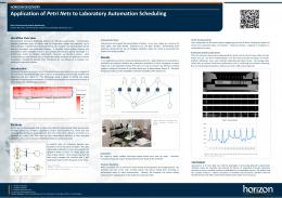
boundedness, liveness, persistence, fairness etc (Oliveira, et al., 2007). The advantages of automated testing are reliability, cost reduction and fastness. 3. MAS Testing This paper focuses on proposing a PN based approach for MAS behavior testing. In this section, a conversion model is presented for adopting the MAS design/analysis models created based on MaSE methodology into standard UML 2.0 models and then the UML models are transformed to PNs for formal testing. The MAS proposed approach overview is shown in Figure 1. The approach is divided into two main modules: Module 1: Constructing MAS behavioral model: a conversion model is proposed to transform the MaSE design/analysis artifacts into standard UML 2.0 models. This module uses the MaSE models as input and constructs the MAS behavioral models based on UML models. Module 2: Converting behavioral model to PN: a conversion model is proposed to transform the UML 2.0 models into PNs model. This module uses the UML models as input and constructs the MAS behavioral models based on PN model. 3.1 Constructing MAS Behavioral Model MAS’s agents communicate by message exchanges. A common type of interaction diagrams in UML is a sequence diagram which is useful design tools because it provides a dynamic view of the system behavior, which can be difficult to extract from static diagrams or specifications. The sequence of messages is helpful for fault detection during communications. A proposed method for transforming the agents’ conversations from MaSE to UML sequence diagrams is introduced in this section. The MAS sequence diagram is not given by MaSE and must be constructed using information provided by the MaSE artifacts like agent class diagrams and role diagrams (Bergenti, et al., 2004). The role sequence diagram in “Applying Use Cases” stage of MaSE analysis phase presents the communication between roles assigned to each agent. The agent class diagram is created in the MaSE “Constructing Agent Classes” stage and represents the entire agent system organization composing of agent classes and relationships among them. An agent class is a model for an agent’s type with the system roles it plays. Multiple role assignments to an agent clearly show the ability of agent to play assigned roles concurrently or sequentially. The MaSE agent class diagram is similar to UML class diagram in object oriented design but the difference is that the MaSE agent classes are defined by roles, not by attributes and operations. Moreover, relationships are communications between agents (DeLoach, 2009). Figure 2 and Figure 3 show the hypothetical examples of MaSE agent class diagram and role sequence diagram. The approach for constructing UML sequence diagram based on the two above mentioned MaSE diagrams is defined as follow (See Figure 4). Each role sequence diagram is looked for the roles which are listed in the same agent class in the agent class diagram. Therefore, all roles in each role sequence diagram are classified based on the agent, which they belong to. Then, each class matches to an agent class in agent class diagram and the exchanged messages with other classes are identifiable. At this moment, an UML sequence diagram can be produced from agent class diagram which the lifelines are agents’ class. The recognized messages between each two classes are registered into UML sequence diagram as a new communication. For example, in Figure 3, the role sequence diagram is classified into three different classes, the first one consists of Role 1 and Role 2 and the second one is composed of Role 3 and Role 4 and the last one contains Role 5. The first class corresponds to agent class 1, the second one corresponds to agent class 2, and the third one corresponds to agent class 3. The constructed UML sequence diagrams from role sequence diagram and agent class diagram are shown in Figure 5. 3.2 The Transformation of UML Sequence Diagram to PNs The aim of this stage is to convert the sequence diagram (components and their sending messages) to PNs. In converting the sequence diagram to PN, the proposed idea by (Emadi & Fereidoon, 2009) was used. Given a UML sequence diagram sdi, the approach taken for its transformation into a PNs model consists of the following steps (see Figure 6): Transforming each of the components of sdi, that send or receive a message, to a PN subsystem. This transformation will associate each component to equivalent PN subsystem.
Published by Canadian Center of Science and Education
49
www.ccsenet.org/mas
Modern Applied Science
Vol. 6, No. 3; March 2012
Joining the obtained PN subsystems of previous step to obtain a whole PN. In this step, from extracted PNs of the previous step, a final PN can be obtained. This PN is based on message passing between sender and receiver components. Defining the initial marking on the final PN. Figure 7 introduces the four basic types of sequence diagram constructors (sequential, alternative, parallel and loop) and their associated PNs. The sequential operators corresponding to messages in Figure 7.a1 are transformed to their equivalent PNs in Figure 7.a2. Figure 7.b2 presents the PN sub-net modeling the alternative choice between ev1 and ev2. The supplementary subnets are placed inside a dotted box. Figure 7.c2 depicts the PN modeling of the optional choice. Consider that the choices are probabilistic. The weights of the conflicting transitions t1 and t2 are obtained from the stereotypes and label values attached to the constraint condition. Figure 7.d2 shows the PN sub-net corresponding to the parallel execution of ev1 and ev2. Finally, Figure 7.e2 and Figure 7.e3 demonstrate the PN sub-net modeling, a while-do loop and repeat-until, respectively. According to the proposed algorithm, the equivalent PN of sequence diagram (Figure 5) is shown in Figure 8. 4. Similar Works The rest of this section surveys recent and active work on testing software agents. Exiting researches in MAS testing have addressed the verification aspects. Verification is concerned with the checking the internal consistency of the system specifications (Bergenti, et al., 2004). Verification is also often equated with proof of correctness, which proves equivalency of programs to formal specifications (Howden, 1986). Existing works on MAS verification are classified into two categories: axiomatic and model checking approaches. Axiomatic approaches are defined as the theorem proving problems which needs high skills in logics. The axiomatic techniques are defined as a logical theory extraction by: Deriving the axioms from the MAS program that describes the program behavior, and Demonstrating that the specification is a logical consequence of (is a theorem) the program theory (Wooldridge & Ciancarini, 2000; Wooldridge, 1992). In design by contract (Mitchell & Mckim, 2002) pre- and post-conditions and invariants for the methods or procedures are defined and verified in runtime. Violating any of them raises an exception. Also in (Wooldridge, 1992), an axiomatic approach to MAS verification was introduced using the MAS programming languages such as AGENT-0 (Shoham, 1993) and METATEM (Hepple, 2011) and temporal logic. The idea uses temporal belief logic to extract the axioms from the properties of two multi-agent programming languages (AGENT-0 and METATEM). Given such the derived axioms, a program theory representing the properties of the system, is systematically derived (Wooldridge, 1992). But the problem with this technique is they do not check program correctness‚ it just informs that a contract has been violated at runtime. According to the (Wooldridge, 1992), the axiomatic approaches suffer from two main problems. First, the designed agent operation should be sufficiently simple that its properties can be converted into axioms in the logic. The Second problem is the difficulty of the proof problem for agent specification languages. The theoretical complexity of proof for many of these logics is quite overwhelming. Model checking approaches appear to be more adequate in industry, because they have less complexity and better traceability as compared to axiomatic. These approaches aim verifying concrete system characteristics (e.g. liveness, deadlock free, undesirable emergent behaviors) based on an input model of the system under verification. Automatic verification of multi-agent communication using agent Tool (Timothy & DeLoach, 2000) and model checking MAS with MABLE programming language (Wooldridge, et al., 2002) are a few examples of model checking approaches that both use SPIN model checker (Baier & Katoen, 2008). SPIN model checker is a checking tool for fault detection in the design models of software systems. These model checking approaches requires translating the system into a model specified with a concrete language. SPIN model checker uses as input a language named PROMELA (Baier & Katoen, 2008). In (Timothy & DeLoach, 2000), the agent Tool is used to create agent conversations graphically based on MaSE state transition diagrams. The graphical representations are converted into formal PROMELA that is analyzed by the SPIN model checker to detect errors such as deadlock, non-progress loops, syntax errors, unused messages, and unused states. As it is discussed in (Bergenti, et al., 2004) and to the best of the author’s knowledge, none of the existing works in model checking uses the graphical models and the model based testing techniques (e.g. PN (Oliveira, et al., 2007)) for MAS verification.
50
ISSN 1913-1844
E-ISSN 1913-1852
www.ccsenet.org/mas
Modern Applied Science
Vol. 6, No. 3; March 2012
In this paper, we have proposed a model checking approach for MAS’ behavioral testing using the MaSE methodology design/analysis artifacts. These artifacts (more precisely agent class diagram and role diagram) are transformed into the standard UML 2.0 models (exactly into sequence diagram) using a proposed conversion model. Then, these sequence diagrams are used to generate an equivalent PN. Finally, the analysis techniques of PN can be applied to automatic MAS testing. Specifically, the proposed approach contributes to the existing AOSE methodologies by providing: A complete and comprehensive testing process for MAS. Reducing/removing side effects in test execution and monitoring because introducing new entities in the system, e.g., mock agents tester agents, and monitoring agent as in many approaches, can influence the behavior of the agents under test and the performance of the system as a whole. Testing emergent properties at macroscopic system level. 5. Conclusion The agent interaction in MAS context can conceivably lead to behavioral failures in runtime, including deadlock. Hence, testing and monitoring MAS to eliminate the risk of unwanted emergent behaviors is an important precondition for introducing MAS to the main stream of commercial software. Most of the exiting testing techniques for MAS have addressed the MAS verification aspects. This paper describes a systematic and automatable approach to test MAS design models using PN theory. The MAS design models, consisting of Agent class diagram and Agent sequence diagram built based on the MaSE methodology, are converted to UML sequence diagram which are used to generate an equivalent PN diagram. Since PNs are formal language, they are used for automatic checking of MAS’ behavioral properties thereby eliminating human errors. In this study, we have presented a process for MAS behavioral testing. On the other hand, each MAS is composed of several agents whose roles are the building blocks used to determine agent’s classes and capture system goals. Each role consists of several tasks and each task can be described by a MaSE task diagram. In the future work, we will investigate agent behavioral testing by constructing agent behavioral model based on the MaSE task diagram. References Athamena, B., & Houhamdi, Z. (2012). Structured acceptance test suite generation process for multi-agent system. Computer and Information Science, 5(1), 55-61. http://dx.doi.org/10.5539/cis.v5n1p55 Baier, C., & Katoen, J. P. (2008). Principles of Model Checking. The MIT Press, Pages: 975. http://dx.doi.org/10.1093/comjnl/bxp025 Bergenti, F., Gleizes, M., P., & Zambonelli, F. (2004). Methodologies and Software Engineering for Agent Systems. Multiagent Systems, Artificial Societies, and Simulated Organizations, 11. http://dx.doi.org/10.1007/b116049 DeLoach, S. (2009). Moving Multiagent Systems from Research to Practice. International Journal of Agent-Oriented Software Engineering, 3(4), 378-382. http://dx.doi.org/10.1504/IJAOSE.2009.025315 DeLoach, S. (2004). The MaSE Methodology. In: Bergenti, F., Gleizes, M., P., & Zambonelli, F. (Eds.) Methodologies and Software Engineering for Agent Systems. Multiagent Systems, Artificial Societies, and Simulated Organizations, 11(II), 107-125. http://dx.doi.org/ 10.1007/1-4020-8058-1_8 Elamy, A., & Far, B. (2008). A Statistical Approach for Evaluating and Assembling Agent Oriented Software Engineering Methodologies. In Agent-Oriented Information Systems IV, 4898/2008, Berlin/Heidelberg: Springer, 105-122. http://dx.doi.org/10.1007/978-3-540-77990-2_7 Emad, S., & Fereidoon, S. (2009). A new executable model for software architecture based on Petri Net. Indian Journal of Science and Technology, 2(9), 15-25. [Online] Available: http://indjst.org/archive/vol.2.issue.9-10/sep09emadi-3.pdf Hepple, A. (2011). Introduction to MetateM. http://www.csc.liv.ac.uk/~anthony/metatem.html
University
of
Liverpool. [Online]
Available:
Houhamdi, Z. (2011a). Multi-agent system testing: A survey. International Journal of Advanced Computer Science and Applications, 2(6), 135-141. http://dx.doi.org/10.3844/jcssp.2011.690.697
Published by Canadian Center of Science and Education
51
www.ccsenet.org/mas
Modern Applied Science
Vol. 6, No. 3; March 2012
Houhamdi, Z., & Athamena, B. (2011a). Structured integration test suite generation process for multi-agent system. Journal of Computer Science, 7(5), 690-697. http://dx.doi.org/10.3844/jcssp.2011.690.697 Houhamdi, Z., & Athamena, B. (2011b). Structured system test suite generation process for multi-agent system. International Journal on Computer Science and Engineering, 3(4), 1681-1688. [Online] Available: http://www.enggjournals.com/ ijcse/doc/IJCSE11-03-04-036.pdf Howden, W. E. (1986). A Functional Approach to Program Testing and Analysis, IEEE Transactions on Software Engineering, 12(10), 997-1005. Huget, M., & Demazeau, Y. (2004). Evaluating multi agent systems: A record/replay approach. In Proceedings of the IEEE/WIC/ACM International Conference on Intelligent Agent Technology (IAT’04), 536-539. http://dx.doi.org/10.1109/IAT.2004.1343013 Mitchell, R., & Mckim, J. (2002). Design by contract, by example. USA: Addison-Wesley Longman Publishing Co. Nguyen, C., Perini A., & Tonella, P. (2010). Goal oriented testing for MASs. International Journal of Agent-Oriented Software Engineering, 4(1), 79-109. http://dx.doi.org/10.1504/IJAOSE.2010.029810 Oliveira, E., Almeida, H., & Silva, L. (2007). Formal modeling and verification of a software component model using colored Petri nets and model checking. In Proceeding of 2007ACM Symposium Applied Computing, 1427-1431. http://dx.doi.org/10.1145/1244002.1244309 OMG, Object Management Group (2007). UML 2.1.1 Superstructure Specification. [Online] Available: http://www.omg.org/spec/UML/2.1.1/ Superstructure/PDF/ Shoham, Y. (1993). Agent-oriented programming, http://dx.doi.org/10.1016/0004-3702(93)90034-9
Artificial
Intelligence,
60(1),
51-92.
Timothy, H. L., & DeLoach, S. (2000). Automatic Verification of Multi-agent Conversations. In the Annual Midwest Artificial Intelligence and Cognitive Science Fayetteville. [Online] Available: http://www.dtic.mil/cgi-bin/GetTRDoc?AD=ADA446531 Wooldridge, M. J., & Ciancarini, P. (2000). Agent-Oriented Software Engineering: The State of the Art. In Proceeding of the Workshop on Agent-Oriented Software Engineering, 1-28. http://dx.doi.org/10.1007/3-540-44564-1_1 Wooldridge, M. (1992). The Logical Modelling of Computational Multi-Agent Systems, PhD Thesis, The University of Manchester, Manchester, UK. Wooldridge, M. J., Fisher, M., Huget, M., & Parsons, S. (2002). Model Checking Multi-Agent Systems with MABLE. In Proceedings of the first international joint conference on Autonomous agents and multiagent systems part 2 - AAMAS '02, 952–959. http://dx.doi.org/10.1145/544862.544965 Start MaSE Models UML Sequence Diagram Construction UML Models Petri Net Conversion PN Models Validation
End Figure 1. MAS Design Testing Flowchart
52
ISSN 1913-1844
E-ISSN 1913-1852
www.ccsenet.org/mas
Modern Applied Science
Vol. 6, No. 3; March 2012
Detect Notify
File Monitor
Login Monitor
FileNotifier() LoginNotifier()
FileModifiedDetector(...
LoginDetector()
Notifier AdminNotifier()
UserInterface User()
Figure 2. Agent Class Diagram
File Delitation Detector
File Modified File Notifier Detector Modify File Violation
Admin Notifier
User
Delation File Violation Request Notification
Notify
Acknowledge Notification Complete
Reported
Reported
Figure 3. Role Sequence Diagram
Published by Canadian Center of Science and Education
53
www.ccsenet.org/mas
Modern Applied Science
Vol. 6, No. 3; March 2012
Start RD =Role Diagram
Identify Roles RL = Role List RL ≠ Null
True Agent Class Diagram
Identify Role Agent Class
False
Role Categorization CS: Categories Set Recognize Messages between Categories
Next
RL
Draw Sequence Diagram SD: Sequence Diagram End
Figure 4. UML Sequence Diagram Construction Flowchart
54
ISSN 1913-1844
E-ISSN 1913-1852
www.ccsenet.org/mas
Modern Applied Science
File Monitor
Detect Notify
Vol. 6, No. 3; March 2012
Notifier
User Interface
Modifier File Violation
Deletation File Violation Request Notification
Notify
Acknowledge
Notification Complete Modifier File Reported
Delete File Reported
Figure 5. UML Sequence Diagram Start SD =Sequence Diagram PNL Null PNL: Petri Net List Decompose SD to Components CL = Component List CL ≠ null
False PNL
True Transform CL to PN
Join FPN: Final Petri Net
PN: Petri Net Insert (PNL, PN)
Define Initial Marking
PNL Next CL
End
Figure 6. Sequence Diagram Conversion to PN
Published by Canadian Center of Science and Education
55
www.ccsenet.org/mas
Modern Applied Science
Vol. 6, No. 3; March 2012
Figure 7. PN Models for Sequence Diagram Structures
56
ISSN 1913-1844
E-ISSN 1913-1852
www.ccsenet.org/mas
Modern Applied Science
A
Vol. 6, No. 3; March 2012
C
B
D
1
2
3
4
5
6
7
8
Figure 8. Equivalent PN of UML Sequence Diagram
Published by Canadian Center of Science and Education
57