Petri Net Based Modelling and Simulation of Email Alert System Juraj Puksec', Miljenko Opsenica', Domagoj Frank', Vlatka Maricic', Kimon P. Valavanis2, Senior Member, IEEE, Ignac Lovrek3, Member, IEEE
-
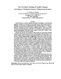
Abstract The paper presents modelling, simulation and checking of Email Alert System service by using Pem' nets. Petti net models are used in the early design phases for formal verification of the service solution characterised by concurrent processes and threads, as well as hardware parallel ability. Case study discussing call design approach is included. Index Term -Internet service, email, Petri net, modelling.
I. INTRODUCTION The integration of Internet services and Telephony services opens a new area in telecommunication for the development of services such as Email Alert System (EMA System). The EMA System service eliminates the need for permanent Internet connection. The EMA System checks users mailbox on the mail server and once a new email has been detected, the user will be informed over the phone [ 1, 21. The Email Alert System developed for implementing this service consists of seven modules. The communication in the EMA System is based on Component Object Model (COM) technology, which enables global applications independence from programming languages and full network transparency. Problems related to such implementation are concurrency between processes, threads and hardware parallel ability. This paper deals with modelling, simulation and checking of the EMA System solutions by using Petri nets. The main goal of derived Petri net models has been to verify formally the proposed solutions, particularly their liveness property, in early phases of the project in order to avoid potential deadlocks and possible conflicts. The paper is organised as follows: Section I1 deals with a description of the EMA System. Voice Machine Module chosen as a case study is presented in Section 111, while its Petri net model is given in Section IV.Section V discusses simulation results. Conclusions are given in the last section.
' Ericsson Nikola Tesla, Krapinska 45, HR - loo00Zagreb, Croatia. Email:
[email protected]
* University of Louisiana at Lafayette, Center for Advanced Computer Studies, Lafayette, USA, and Technical University of Crete, Dept. of DPEM, Greece. University of Zagreb, Faculty of Electrical Engineering and Computing,
Zagreb, Croatia.
11. EMAILALERTSYSTEM One of the most popular Internet services is email, but its deficiency is the inavailability of service. User has to connect to the Internet to check for new email without knowing if any or some specific arrived. Also, it is not possible to access Internet at any time and at any place. The EMA System offers solutions for users by periodically scanning user's mailbox on the mail server and informing users about arrived emails via telephone. A user of the EMA System can be anyone with a telephone subscription and an Internet accessible email account on a mail server that supports POP3 or IMAP4 protocol.
Figure I
- The EMA System in three layer structure
The EMA System consists of seven modules: Web Interface, Console, Web Handler, Database, Controller, Mail Checker and Voice Machine (Fig. 1). The EMA System processes can be divided into three main layers: presentation, application and data layer. Users can register to the EMA System service via the Web Interface or via the Console. User data is stored in Database through the Web Handler. The Web Handler immediately sends an email to the user carrying hidher Personal Identification Number (PIN). When the user gets hidher PIN number he/she can activate the EMA System service. After the activation the Controller picks up user data from Database and requests from the Mail Checker to scan the user's mailbox (or mailboxes). The Mail Checker sends a message to the Controller after detecting of new email. The Controller reads the user's notification phone number and
lo* Mediterranean Electrotechnical Conference, MEleCon 2000, Vol. I 0-7803-6290-X/00/$10.00 02000 IEEE
49
sends a notification request to the Voice Machine. When the user receives the call from the Voice machine he/she must enter hidher PIN number. If the PIN number is correct a voice message will be played. Users also had to decide will the service stay active or will he/she deactivate it. The EMA System is implemented on a Win32 platform [3]. Modules were developed by using C, C++, HTML, ASP, Java Script and VB Script. The EMA System implementation includes Computer Telephony Integration (CTI), programming interface, concurrency control and synchronisation demands. Modules are independent and do not necessarily reside on the same host. Network transparency and differences in data representation are resolved by COM middleware technology [4]. The Controller communicates with other modules by using COM, except communication with the Database is through ActiveX Data Object (ADO) using SQL queries. 111. CASE STUDY: VOICE MACHINE MODULE The Voice Machine acts as an interface between a user and the EMA. System that uses a Public Switched Telephone Network (PSTN). The hardware part of the Voice 'Machine includes an integrated add-on board with voice processing capability, and an analogue or digital line interface. The software part of the Voice Machine handles requests from the Controller and initiates notification call towards service user, Figure 2. Notification call is state-machine controlled. If new email is detected, the Controller sends the request to the Voice machine to initiate an alert call by passing user's UID (user identification number), telephone number and PIN. The Voice Machine starts alert call on the
Figure 2
- Modules communication in the EMA System
available channel by triggering the transition from state IDLE to OFFHOOK, in the Call State diagram, Figure 3. If all channels are busy, the request will wait till timeout occurs. Call State machine controls voice processing, call establishment, call progress, user keypad input and billing information collection from the telephone exchange. UID, Call outcome (successful notification, user busy, not answered etc.) and service activity flag (if service is active or not) is then sent back to the Controller. I v . DESIGNOF CALL STATE DIAGRAM The Voice Machine Call State diagram is shown in Figure 3. Call State diagram contains 14 states divided in three main classes: Hook, Play and Digit plus Idle and FallBack. Request from the Controller initiates transition from IDLE I
I
-
Figure 3 Call State Dingram
50
lomMeditemean Electrotechnical Conference, MEleCon 2000, Vol. I
to OFFHOOK state which starts the call by setting the telephone line “off hook”. If the operation is successful, state machine transits to DIAL which initiates dialling of user’s extension number. If the call is answered, PLAY-INTRO state plays the voice message which requests PIN to be entered by using keypad. DIG-PIN state collects keypad entries and tests if the correct PIN is entered. If the user provides correct PIN, confirmation message is played by PLAY-CONFF’IN state. Otherwise, PLAY-INVPIN plays rejection message. If the correct PIN is entered, the notification is considered successful. After PIN is checked, user can deactivate the service or leave it activated by providing appropriate keypad input. Input is tested in similar manner as PIN input. If user decides to stop the service, PLAY-OFFSERVICE notifies that the request is processed. At the end, PLAY-GOODBYE greets the user and ONHOOK ends the call. The state machine is put to IDLE state which sends the call outcome to the Controller. In order to minimise the number of states, all events that do not pertain to “regular” call sequence initiate transition to FallBack state. Those events are the following: unanswered or busy call, user hang-up during call, timer exceeded, too many retries and any error or unexpected event.
AND SIhWLATION v . PETRI NETBASEDMODELLING In order to verify the module formally, call state diagram is transformed into Petri net [5, 6,7], Figure 4. The main goal of derived Petri net models has been checking the formal properties of the proposed solution, particularly liveness, in early phases of the project in order to avoid potential deadlocks and conflict activities. Petri net is constructed by transforming the Call State machine diagram. All states are transformed into places and they are connected with transitions. Inhibition arcs were used for modelling error conditions. This is explained by the fact that from every regular place transition is possible to next regular place but if some error occurs the call drops to the FallBack place. Visual Object Net ++ [8] tool has been used for testing the EMA System modules. Different situations are investigated by simulating Voice Machine operations. The most important test cases defining successful and unsuccessful call are described by transition sequences and short explanations, as follows:
-
Figure 4 Petri net of the Voice Machine module
~~
10* Meditekmean Electrotechnical Conference, MEleCon 2000, Vol. I
51
1) Regular call flow
Regular call flow means that user enters hidher PIN and SERVICE number correctly. The following transition sequence describes regular call flow: P1+
tl t15
.51P
t3
P
3
t5
d P5 +w+P9+ -P13----
t7
t9
t13
t23 t 24 t27 P17 dP 2 4 d P 2 7 dP1.
The call is considered as successful. 2) Call flow with errors All errors happening during the call initiate the call release and the call drops to the FallBack state. An example showing error during notification call, before PIN entering, (P8#0) produces the following transition sequence: tl t3 t5 t8 Pl*P3*F5*P7,P8+F2~F27dPl.
t26
t27
From the simulation results we can conclude that the constructed Petri net is error-free. Only after the Petri net simulation was performed, the programming of Voice Machine module took place.
CONCLUSION Modelling, simulation and checking of Email Alert Internet services by using Petri nets is described in the paper. Call model for Voice Machine and its Petri net model are elaborated as a case study. Petri net models were used for clarifying service concepts and implementation. Formal verification and simulation based on derived Petri net proved to be useful in early design phases. Petri net models and the analysis based on them were found to be an efficient way to improve design process and project controllability. This is important especially for new telecom services combining features from different networks, such as Internet and telephone network.
The call is considered as unsuccessful.
REFERENCES
3) User enters invalid service number User enters invalid service number (P19#0). After entering the correct number, the call is terminated regularly. The corresponding transition sequence follows: PI
P
3
A P5 t 5 P 7
LP
P17, P 1 9 A P20-%P17-%
9
5 P13&PIS&
P24’24P27’27P1.
The call is considered as successful. 4) Service deactivation Users decision to deactivate the service (P2 1#0) initiates the following transition sequence: Pl&PlJ+P5-W+P9-p t3 13--\PlS--tr5
17
t9
t17 t 22 t24 Pl7,P21dP22+P24~P27-P1.
t13
t15
t27
D. Frank, H.Lucic, M. Opsenica, J. Puksec, M. Zic, S. Brajkovic, V. Maricic, “The EMA System: A CTI-Based E-Mail Alerting Service”, lEEE Communications Magazine, vol. 38, no. 2, February 2000, pp. 122 - 128. M. Opsenica. D. Frank, J. Puksec, “EMA System and Concurrence Solution”, Proc. of SofCOM ’99 Con$, Split-Rijeka-Trieste-Venecie, Croatia-ltaly, 13”’-16* October 1999, pp. 279 - 287. J. M. Hart,“Win32 System Programming”, Addison Wesley Longman inc., 1997. D. Box, “Essential C O M , Addison Wesley Longman inc., 1998. J. L. Peterson, “Petri Net Theory and the Modeling of systems”, Prenrice-Hall, Englewood Cliffs, 1981. I. Lovrek, “Modelling Telecommunications Processes - Theory and Application of Petri Nets”, Skolska knjiga, Zagreb, 1998. (in Croatian). S. Ramaswamy, K. P. Valavanis, S. Barber, ”Petri Net Extensions for the Development of MIMO Models for Automated Manufacturing Systems”,Journal of Manufacturing Systems, Vol. 16, No. 3, pp: 175191, 1997. [8] R. h t h , “Visual Object Net++ 2.0”. http://www.systemtechnik.tuilmenau.dd-drath/.
IDLE condition is restored. 5 ) User enters invalid PIN
User enters invalid PIN number (P11#0). After PIN correction user decide to deactivate the service. The following transition sequence is produced: P1’1P3--%ps-%P7’7P9,P1
l&Pl2%F94
Pl3113Pl5~Pl7.P21’17’P22t22.P24124P27f27Pl.
The call is considered as successful. There are no deadlocks in the model. Conflict transitions are only transitions that model regular call continuation and error-initiated call termination, such as: (tl, t2), (t3, t4), (ts, t6). (t7, t8), (t9, t10, t12), (t13, t14), (t15, t16), (t17, t18, t20,t23), (t21, t22) and (t24. t25). All these conflicts are intentional. They describe mutually exclusive actions. The Petri net proves to be live, and there are no deadlocks in the model.
52
Mediterranean Electrotechnical Conference, MEleCon 2000, Vol. I