ELECTRONICS AND ELECTRICAL ENGINEERING ISSN 1392 – 1215
2009. No. 2(90) ELEKTRONIKA IR ELEKTROTECHNIKA TELECOMMUNICATIONS ENGINEERING
T180 ──────────────────────── TELEKOMUNIKACIJŲ INŽINERIJA
A Platform for Adaptive Equalization Prototyping Ž. Nakutis Electronic and measurement systems department, Kaunas University of Technology Studentų str. 50-443, LT-51368 Kaunas, Lithuania, phone: +370 37 300883; e-mail:
[email protected] universities communication and digital signal processing related courses [9, 10] and handbooks. Due to the need of adaptive features the implementation of adaptive filters historically is targeted by the software of high performance digital signal processors. However, adaptive equalizer hardware prototyping is usually avoided, but computer simulation is used instead, utilizing such tools as Matlab/Simulink Communication toolbox. Even though, many features of the equalizers can be modeled, but their hardware implementation should also be of importance both for teaching needs and research results verification. The goal of this paper is to present and analyze adaptive equalizers prototyping platform.
Introduction Adaptive equalization is a mature technology in the field of data communication. Goal of a channel equalizer is to mitigate distortions caused by the communication channel and reduce ISI (Inter Symbol Interference). Due to the initially unknown communication channel transfer function or its nonstationary nature adaptive equalizers became the most often solution at the receiver. Theoretical fundamentals of linear and non-linear equalizers were developed in the 1970-1990 as summarized in tutorial reviews [1]. However, interest in the adaptive equalization is still noticeable in the scientific papers until now [2, 3]. Indeed, in addition to the classical applications in the DSL modems [1] and wireless (radio) communications [4] adaptive equalization is proposed for underwater (acoustic) telemetry systems [5], for optical transceivers [6], for read channels in magnetic hard driver data disks [7], for terrestrial digital video broadcasting receivers [8], etc. Even in the communication systems where channel distortions are in principal targeted by alternative solutions like spread spectrum modulation, OFDM or CDMA [4], adaptive equalizers are useful ever after [2]. Linear adaptive equalizer operation is based on the adaptive LMS filters. Nonlinear equalizers use the most likelihood sequence equalizers (Viterbi algorithm) and employ detected symbols to reconstruct most probably transmitted sequence. Hardware implementation of adaptive equalizers is also in the scope of recent publications [3, 6]. Because of its well developed theoretical background and common use in various communication systems the adaptive equalization became a must topic in many
Tools and experimental setup A setup for adaptive DSP algorithms teaching was presented in the paper [9]. Its flexibility allows us to implement equalizer prototype also. After the survey of currently available and widely used hardware tools and supporting software packages intended for the digital signal processing it was proposed to choose the platform composed of Texas Instruments, Inc. DSP Starter Kits DSK6713, Code Composer Development environment and a set of appropriate Mathworks Matlab/Simulink toolboxes. The key component of the Starter Kit is TI digital signal processor TMS32C6713 featuring performance of up to 400 MMACS. The above tools in the last decade gained the leading positions in academic, research and development organizations perhaps due to their reliability, excellent support and documentation, continuous updating of the
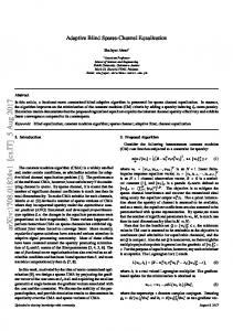
Fig. 1. Models mapping to hardware and signal representations (digital/analog) in the platform
21
which is routed to the right output channel. Due to the frame based (buffered) sampled signals processing in the channel model implementation (DSK1) the necessary delay of reference signal has to be selected higher then the one derived concerning only the order of FIR type channel order. A methodology to fine tune the delay was explained in [9]. Visualization and further processing of both output signals and signals sampled in the intermediate points of the equalizer model is possible both via the sound card input and the JTAG emulator using RTDX data exchange method [9] supported by the Simulink environment. Employment of the PC sound card and standard audio input/output capabilities of the DSK boards (onboard Texas Instruments codecs 320AIC23) defines the applicable prototyping frequency range. Even though it might be significantly lower than the wideband signal frequency range of the real equalizers, the algorithmic implementation of the equalizer is not affected by operation in the lower range. It is schematically presented in the Fig. 1 paths of the analog signals propagation in the platform and signals routes together with the used sampling frequencies. Antialiasing filters are implemented inside the codes and their cut-off frequency is automatically set to the half of sampling frequency.
Fig. 2. Photo of the proposed setup
offered functionality, donation programs for universities, etc. Disadvantages of the selected tools are mostly related to their high technical complexity and high requirements for the workstation. Nevertheless, the development platform abstracts the end user from low level programming by utilizing target executable code generation from the graphical representation of a channel equalizer model. Platform for channel equalizer prototyping The platform for equalizer prototyping should consist not only from the equalizer itself but also from the excitation and data acquisition means. Their mapping to the available hardware tools is shown in the Fig. 1. Differently from the similar setup described in the [9] excitation signal generation is implemented not by the PC sound card but by the first DSK board. The advantage of this approach is more simple connections (Left and Right in Fig. 1) between two DSK boards as shown in the Fig. 2 compared to the corresponding connections in the setup described in [9]. Another advantage is the possibility to generate excitation signals not affected by the PC sound card transfer function. A Simulink model implemented by the DSK1 is shown in Fig. 3. Communication channel can be modeled by implementing any model of interest starting from simple FIR filter (dispersive channel) up to complex nonstationary noisy channels.
Equalizer prototype testing Variety of equalizers and their performance parameters can be investigated using the platform. In the Fig. 5 (a) pulses of the excitation and channel model response are given. The equalizer and channel were both excited using single sample pulse with the periodicity of 20 samples (see G in Fig. 1 and Pulse Generator in Fig. 3). The common dispersive channel was modeled by the 3rd order digital FIR filter having the transfer function:
yi
1 cos(2 ai / d ) xi j , 2 j 0 2
(1)
where parameter d 3.5 , coefficients a0 1 , a1 0 ,
a2 1 . Distortion of the excitation pulse in the time domain can be seen in Fig. 5 (a) by observing the response pulse. Sampling frequency of the signals presented in Fig. 5 is 44.1 kHz. Routing the excitation signal to the desired (sometimes called reference) port of the equalizer and the channel response to the input port is necessary prior to the start of equalizer training. In the training stage the LMS filter coefficients are adapted to meet least squares error minimization goal. When the equalizer training is stopped it enters the direct equalization mode. Fig. 5(b) indicates equalized pulse record obtained in the direct equalization mode. It can be clearly seen that pulse distortion introduced by the channel is reduced at the output of the equalizer. This is the evidence of intersymbol interference impact reduction by the equalizer. The quality of the pulse shape reconstruction can be further investigated analyzing signal records obtained using the considered platform in the Matlab environment.
Fig. 3. Simulink model for channel and excitation modeling
A simple channel equalizer based on the normalized LMS adaptive filter is described using Simulink block model shown in Fig. 4. It is implemented using the second hardware board DSK2. The channel equalizer can be put to training or direct equalization mode using on-board switches. In the training mode excitation signal from the generator was routed to the reference (desired) input of the adaptive LMS filter. White noise generator is used instead of pulse generator in training mode. In the direct mode excitation signal comming to the left input of the DSK2 is routed to its left output without any processing for comparison over the equalized output of the LMS filter 22
In
Line In C6713 DSK ADC
SW0 Submatrix From2
O1
SW0 From4
Ctrl O2
Switch1
M ux1 Input In
DSK_ADC SW1 Submatrix1From3
Ctrl O2
-91 z
M ux2
Delay SW2 From
SW1 From5
Output
O1
Desired Normalized LM S
Error Switch2
Adapt
SW3 From1
C6713 DSK DAC M atrix DSK_DAC Concatenate
Wts
Reset LM S Filter
C6713DSK SW2
SW1
Goto2 SW3
Goto1 SW0
Goto3
Goto0
C6713 DSK DIP Switch
1 2 Dec 4 8
C6713 DSK LED
DSK_Switch
BinToDec
DSK_LED
Fig. 4. Channel equalizer Simulink model M agnitude, V 1.5
3 kHz in the period of 10 ms. In Fig. 6(a) we may see decline of the chirp amplitude in the higher frequency range due to channel high frequency filtering. However, at the output of the trained equalizer (Fig. 6(b)) the chirp amplitude is virtually not dependant from the input signal frequency. Some ripple of the amplitude can be explained by the limited sampling frequency of the PC sound card.
(a) Response Excitation
1
0.5 M agnitude, V 1
(a)
0 0.5
-0.5 4.5 M agnitude, V
5
5.5
6
0
(b)
1.5 -0.5
Equalized Excitation 1
-1 8 M agnitude, V 1
0.5
10
12 (b)
14
16
0.5
0
0
-0.5 6
6.5
7
7.5
time, ms Fig. 5. Excitation signal distortion (a) and reconstruction (b) at the equalizer output
-0.5
-1
Channel frequency transfer function equalization can initially be demonstrated using chirp (frequency varying in time domain) signal. The chirp generator therefore was inserted in the model (Fig. 3) instead of the pulse generator. The chirp signal was linearly swept from 0.2 to
16
18 20 22 time, ms Fig. 6. Channel model (a) and equalizer (b) response when excited using the chirp waveform
23
Conclusions 3.
The proposed adaptive equalization prototyping platform can be used as a supplement to simulation in education. The communication channel equalizer is implemented in the hardware similar to the used in telecommunication systems designs, therefore supporting the confidence of the real world applications. The proposed platform is composed from the hardware and software tools that are widely accepted in academic environments and are often supplied by the so called university programs of manufacturers. The platform offers possibilities to test equalizer operation under different channel models. Both equalizer parameters and channel models can be changed easily in the graphical diagram models and implemented in the hardware immediately.
4.
5.
6.
7.
8.
Acknoledgment 9.
Research was supported by EU Structural Fonds (Project BPD2004-ESF-2.5.0-03-05/0083).
10.
References 1. Qureshi, S. Adaptive equalization // Proceedings of the IEEE, Vol. 73, Issue 9. – 1985. – P. 1349–1387. 2. Chen Bor-Sen, B.-S., Liao Jung-Feng, J.-F. Adaptive MCCDMA Multiple Channel Estimation and Tracking Over Time-Varying Multipath Fading Channels, IEEE
Transactions on Wireless Communications, Volume 6, Issue 6. – 2007. – P. 2328–2337. Zhong, W., Mao, Z. Design and VLSI Architecture of a Channel Equalizer Based on Adaptive Modulation for IEEE 802.11a WLAN, IEEE Asia Pacific Conference on Circuits and Systems. – 2006. – P. 1699–1702. Sklar, B. Rayleigh fading channels in mobile digital communication systems .II. Mitigation, IEEE Communications Magazine, Vol. 35, Issue 7. – 1997. – P. 102–109. Aijun Song, Badiey, M. Generalized equalization for underwater acoustic communications, Proceedings of MTS/IEEE OCEANS. – 2005, Vol. 2. – P. 1522–1527. Azadet, K., Haratsch, E. et al., DSP techniques for optical transceivers, IEEE Conference on Custom Integrated Circuits. – 2001. – P. 281-288. Haratsch, E.F., Keirn, Z.A. Digital signal processing in read channels, Proceedings of the IEEE Custom Integrated Circuits Conference. – 2005. – P. 683–690. Sherratt, R.S. Performance and conformance results of the deterministic DVB-T equalizer, IEEE Transactions on Consumer Electronics, Vol. 50, Issue 1. – P. 95–99. Nakutis Ž. Setup for Adaptive DSP Algorithms Teaching, Proceedings of the ITI 2008 30th Int. Conf. on Information Technology Interfaces. – 2008. – P. 939–944. Marozas V., Jurkonis R., Lukoševičius A. Development of Virtual and Remote Lab Experimentation System For Electronics Engineering // Electronics and Electrical Engineering. ISSN 1392–1215. – Kaunas: Technologija, 2008. – No. 7(87). – P. 41–44. Received 2008 10 16
Ž. Nakutis. A Platform for Adaptive Equalization Prototyping // Electronics and Electrical Engineering. – Kaunas: Technologija, 2009. – No. 2(90). – P. 21–24. Hardware prototyping platform for the adaptive equalizer investigation is presented in the paper. The platform consist the equalizer, communication channel, excitation and signal acquisition means that are mapped to two Digital Spectrum Starter Kits based on Texas Instruments DSP and PC sound card. Simulink models of the equalizer, communication channel and excitation generator are compiled and executed by the processors of the DSK boards. The ability of the implemented equalizer to reconstruct shape of the excitation pulses distorted by the communication channel was demonstrated. The proposed adaptive equalization prototyping platform can be used as a supplement to simulation in education. Ill. 6, bibl. 10 (in English; summaries in English, Russian and Lithuanian). Ж. Накутис. Платформа аппаратного моделирования адаптивного эквалайзера // Электроника и электротехника. – Каунас: Технология, 2009. – № 2(90). – С. 21–24. Описывается апаратурная платформа моделирования для исследования адаптивного эквалайзера канала связи. Платформа состоит из эквалайзера, канала связи, инструментов возбуждения и ввода сигналов, которые расспределены между двумя макетами фирмы Digital Spectrum на основе сигнальных процесоров фирмы Texas Instruments и аудио картой персонального компютера. Simulink модели эквалайзера, канала связи и возбуждающего генератора компилируются и выполняются на процессорах макетов. В статье демонстрируется как эквалайзер реконструирует форму импульсов, искажeнных в канале связи. Представленная апаратурная платформа моделирования адаптивного эквалайзера может дополнять подход симулирования в целях обучения. Ил. 6, библ. 10 (на английском языке; рефераты на английском, русском и литовском яз.). Ž. Nakutis. Adaptyviojo vienodintuvo aparatinio modeliavimo platforma // Elektronika ir elektrotechnika. – Kaunas: Technologija, 2009. – Nr. 2(90). – P. 21–24. Aprašyta aparatinė modeliavimo platforma, skirta adaptyviojo ryšio kanalo vienodintuvui tirti. Platforma yra sudaryta iš vienodintuvo, ryšio kanalo, žadinimo ir signalų įvedimo priemonių, kurių realizavimas yra paskirstytas dviejuose firmos „Digital Spectrum“ maketuose su „Texas Instruments“ skaitmeniniais signaliniais procesoriais ir asmeninio kompiuterio garso plokštėje. Vienodintuvo, ryšio kanalo ir žadinimo generatoriaus „Simuliuok“ paketo modeliai yra kompiliuojami ir vykdomi maketuose esančiais procesoriais. Parodomas vienodintuvo gebėjimas rekonstruoti kanalo iškraipytą žadinimo impulsų formą. Pasiūlyta adaptyviojo vienodintuvo aparatinio modeliavimo platforma gali būti naudojama kaip priedas imituoti mokymo tikslais. Il. 6, bibl. 10 (anglų kalba; santraukos anglų, rusų ir lietuvių k.).
24