(IJACSA) International Journal of Advanced Computer Science and Applications, Vol. 2, No.3, March 2011
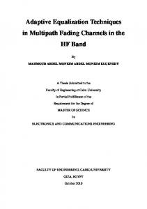
Adaptive Equalization Algorithms:An Overview Amandeep Singh Sappal Electronics & Communication Engineering Punjabi University Patiala Punjab, India
[email protected]
Garima Malik Electronics & Communication Engineering Punjabi University Patiala Punjab, India
[email protected]
Abstract—The recent digital transmission systems impose the application of channel equalizers with short training time and high tracking rate. Equalization techniques compensate for the time dispersion introduced by communication channels and combat the resulting inter-symbol interference (ISI) effect. Given a channel of unknown impulse response, the purpose of an adaptive equalizer is to operate on the channel output such that the cascade connection of the channel and the equalizer provides an approximation to an ideal transmission medium. Typically, adaptive equalizers used in digital communications require an initial training period, during which a known data sequence is transmitted. A replica of this sequence is made available at the receiver in proper synchronism with the transmitter, thereby making it possible for adjustments to be made to the equalizer coefficients in accordance with the adaptive filtering algorithm employed in the equalizer design. In this paper, an overview of the current state of the art in adaptive equalization techniques has been presented.
constant, but, it changes for every different path from the transmitter to the receiver. But, there are also non stationary channels like wireless communications. These channels’ transfer functions vary with time, so that it is not possible to use an optimum filter for these types of channels. So, In order to solve this problem equalizers are designed. Equalizer is meant to work in such a way that BER (Bit Error Rate) should be low and SNR (Signal-to-Noise Ratio) should be high. Equalizer gives the inverse of channel to the Received signal and combination of channel and equalizer gives a flat frequency response and linear phase [1] [4] shown in figure 1.
Keywords- Channel Equalizer; Adaptive Equalize; Least Mean Square; Recursive Least Squares.
Figure 1. Concept of equalizer
I.
INTRODUCTION
One of the most important advantages of the digital transmission systems for voice, data and video communications is their higher reliability in noise environment in comparison with that of their analog counterparts. Unfortunately most often the digital transmission of information is accompanied with a phenomenon known as intersymbol interference (ISI) [1]. Briefly this means that the transmitted pulses are smeared out so that pulses that correspond to different symbols are not separable. Depending on the transmission media the main causes for ISI are: •
cable lines – the fact that they are band limited;
•
cellular communications – multipath propagation
Obviously for a reliable digital transmission system it is crucial to reduce the effects of ISI and it is where the equalizers come on the scene. The need for equalizers [2] arises from the fact that the channel has amplitude and phase dispersion which results in the interference of the transmitted signals with one another. The design of the transmitters and receivers depends on the assumption of the channel transfer function is known. But, in most of the digital communications applications, the channel transfer function is not known at enough level to incorporate filters to remove the channel effect at the transmitters and receivers.For example, in circuit switching communications, the channel transfer function is usually
The static equalizer is cheap in implementation but its noise performance is not very good [3]-[20]. As it is told before, most of the time, the channels and, consequently, the transmission system’s transfer functions are not known. Also, the channel’s impulse response may vary with time. The result of this is that the equalizer cannot be designed. So, mostly preferred scheme is to exploit adaptive equalizers. An adaptive equalizer is an equalization filter that automatically adapts to time-varying properties of the communication channel. It is a filter that self-adjusts its transfer function according to an optimizing algorithm. The rest of this paper is organized as follows. In section II, discussed the basic concept of transversal equalizers are introduced followed by a simplified description of some practical adaptive equalizer. Different adaptation algorithms are discussed in section III. Many methods exist for both the identification and correction processes of adaptive equalization are presented in section IV. The application of adaptive filtering are covered briefly in section V. The conclusion along with future research directions are discussed in Section VI. II.
CHANNEL EQUALIZATION
As mentioned in the introduction the intersymbol interference imposes the main obstacles to achieving increased digital transmission rates with the required accuracy. ISI problem is resolved by channel equalization [5] in which the aim is to construct an equalizer such that the impulse response
62 | P a g e http://ijacsa.thesai.org/
(IJACSA) International Journal of Advanced Computer Science and Applications, Vol. 2, No.3, March 2011 of the channel/equalizer combination is as close to z–Δ as possible, where is a delay. Frequently the channel parameters are not known in advance and moreover they may vary with time, in some applications significantly. Hence, it is necessary to use the adaptive equalizers, which provide the means of tracking the channel characteristics. The following figure shows a diagram of a channel equalization system. Figure3. Adaptive filter
To start the discussion of the block diagram we take the following assumptions: The input signal is the sum of a desired signal interfering noise v (n) Figure2. Digital transmission system using channel equalization
In the previous figure, s(n) is the signal that you transmit through the communication channel, and x(n) is the distorted output signal. To compensate for the signal distortion, the adaptive channel equalization system completes the following two modes:
Training mode - This mode helps you determine the appropriate coefficients of the adaptive filter. When you transmit the signal s (n) to the communication channel, you also apply a delayed version of the same signal to the adaptive filter. In the previous figure, z is a delay function and d (n) is the delayed signal, y(n) is the output signal from the adaptive filter and e(n) is the error signal between d (n) and y (n) . The adaptive filter iteratively adjusts the coefficients to minimize e(n) .After the power of e(n)
d (n) and
x(n) d (n) v(n)
(1) The variable filter has a Finite Impulse Response (FIR) structure. For such structures the impulse response is equal to the filter coefficients. The coefficients for a filter of order p are defined as
wn [ wn (0), wn (1), ..., wn ( p)]T the error signal or cost function is between the desired and the estimated signal
the
(2) difference
(3) e(n) d (n) d (n) The variable filter estimates the desired signal by convolving the input signal with the impulse response. In vector notation this is expressed
d (n) wn * x(n)
(4)
Where
x(n) [ x(n), x(n 1), ..., x(n p)]T
converges, y (n) is almost identical to d (n) ,which means that you can use the resulting adaptive filter coefficients to compensate for the signal distortion.
(5) is an input signal vector. Moreover, the variable filter updates the filter coefficients at every time instant
Decision-directed mode - After you determine the appropriate coefficients of the adaptive filter, you can switch the adaptive channel equalization system to decision-directed mode. In this mode, the adaptive channel equalization system decodes the signal and y (n) produces a new signal, which
Where wn is a correction factor for the filter coefficients .The adaptive algorithm generates this correction factor based on the input and error signals.
is an estimation of the signal delay of Δ taps [6].
s(n) except for a
Here, Adaptive filter plays an important role. The structure of the adaptive filter [7] is showed in Fig.3
wn1 wn wn
III.
(6)
ADAPTATION ALGORITHMS
There are two main adaptation algorithms one is least mean square (LMS) and other is Recursive least square filter (RLS). A. Least Mean Squares Algorithm (LMS) Least mean squares (LMS) algorithms are a class of adaptive filter used to mimic a desired filter by finding the filter coefficients that relate to producing the least mean squares of the error signal (difference between the desired and the actual signal). It is a stochastic gradient descent method in that the filter is only adapted based on the error at the current time. LMS filter is built around a transversal (i.e. tapped delay line) structure. Two practical features, simple to design, yet highly 63 | P a g e
http://ijacsa.thesai.org/
(IJACSA) International Journal of Advanced Computer Science and Applications, Vol. 2, No.3, March 2011 effective in performance have made it highly popular in various application. LMS filter employ, small step size statistical theory, which provides a fairly accurate description of the transient behavior. It also includes H∞ theory which provides the mathematical basis for the deterministic robustness of the LMS filters [1]. As mentioned before LMS algorithm is built around a transversal filter, which is responsible for performing the filtering process. A weight control mechanism responsible for performing the adaptive control process on the tape weight of the transversal filter [9] as illustrated in Figure 4.
Figure4. Block diagram of adaptive transversal filter employing LMS algorithm
The LMS algorithm in general, consists of two basics procedure: Filtering process, which involve, computing the output (d (n d )) of a linear filter in response to the input signal and generating an estimation error by comparing this output with a desired response as follows:
e(n) d (n) y(n)
B. Recursive Least Square Algorithm (RLS) The Recursive least squares (RLS)[11] adaptive filter is an algorithm which recursively finds the filter coefficients that minimize a weighted linear least squares cost function relating to the input signals. This in contrast to other algorithms such as the least mean squares (LMS) that aim to reduce the mean square error. In the derivation of the RLS, the input signals are considered deterministic, while for the LMS and similar algorithm they are considered stochastic. Compared to most of its competitors, the RLS [11] exhibits extremely fast convergence. However, this benefit comes at the cost of high computational complexity, and potentially poor tracking performance when the filter to be estimated changes. As illustrated in Figure 5, the RLS algorithm has the same to procedures as LMS algorithm, except that it provides a tracking rate sufficient for fast fading channel, moreover RLS algorithm is known to have the stability issues due to the covariance update formula p(n) [13], which is used for automatics adjustment in accordance with the estimation error as follows: [14].
p(0) 1I (9) Where p is inverse correlation matrix and is regularization parameter, positive constant for high SNR and negative constant for low SNR. For each instant of time
(7)
(n) p(n 1)u(n) ( n) k ( n) u H (n) (n)
y(n) is filter output and is the desired response at time n Adaptive process, which involves the automatics adjustment of the parameter of the filter in accordance with the estimation error.
i.
ii.
iii. iv.
LMS is the most well-known adaptive algorithms by a value that is proportional to the product of input to the equalizer and output error. LMS algorithms execute quickly but converge slowly, and its complexity grows linearly with the no of weights. Computational simplicity In which channel parameter don’t vary very rapidly [10].
(10) (11)
Time varying gain vector
wˆ (n 1) wˆ (n) (u)e (n) (8) Where is the step size, (n 1) = estimate of tape weight vector at time (n 1) and If prior knowledge of the tape weight vector ( n) is not available, set ( n) 0 The combination of these two processes working together constitutes a feedback loop, as illustrated in the block diagram of Figure 4. First, we have a transversal filter, around which the LMS algorithm is built; this component is responsible for performing the filtering process. Second, we have a mechanism for performing the adaptive control process on the tap weight of the transversal filter- hence the designated “adaptive weight –control mechanism” in the figure [1].
n 1, 2,3.....
(n) d (n) wˆ H (n 1)u(n)
(12)
Then the priori estimation error
wˆ (n) wˆ (n 1) k (n) (n)
(13)
Figure5. Block diagram of adaptive transversal filter employing RLS algorithm
IV.
ADAPTIVE EQUALIZATION TECHNIQUES
Different kinds of Equalizer are available in the text like Fractionally Spaced Equalizer, Blind Equalization, DecisionFeedback Equalization, Linear Phase Equalizer, T-Shaped Equalizer, Dual Mode Equalizer and Symbol spaced Equalizer. But most widely used equalizers are discussed as follow:
64 | P a g e http://ijacsa.thesai.org/
(IJACSA) International Journal of Advanced Computer Science and Applications, Vol. 2, No.3, March 2011 A. Symbol Spaced Equalizer A symbol-spaced linear equalizer consists of a tapped delay line that stores samples from the input signal. Once per symbol period, the equalizer outputs a weighted sum of the values in the delay line and updates the weights to prepare for the next symbol period. This class of equalizer is called symbol-spaced [20] because the sample rates of the input and output are equal. In this configuration the equalizer is attempting to synthesize the inverse of the folded channel spectrum which arises due to the symbol rate sampling (aliasing) of the input. In typical application, the equalizer begins in training mode together information about the channel, and later switches to decision –directed mode. Here, The new set of weights depends on these quantities:
The current set of weights The input signal The output signal For adaptive algorithms other than CMA, a reference signal, d, whose characteristics depend on the operation mode of the equalizer.
need not be synthesized in the feed forward filter, therefore excessive noise enhancement is avoided and sensitivity to sampler phase is decreased.
Figure7. Decision feedback equalizer
The advantage of a DFE implementation is the feedback filter, which is additionally working to remove ISI, operates on noiseless quantized levels, and thus its output is free of channel noise. One drawback to the DFE structure surfaces when an incorrect decision is applied to the feedback filter. The DFE output reflects this error during the next few symbols as the incorrect decision propagates through the feedback filter. Under this condition, there is a greater likelihood for more incorrect decisions following the first one, producing a condition known as error propagation. On most channels of interest the error rate is low enough that the overall performance degradation is slight.
Figure6. Symbol spaced Equalizer
B. Decision-Feedback Equalization The basic limitation of a linear equalizer, such as transversal filter, is the poor perform on the channel having spectral nulls. A decision feedback equalizer (DFE) is a nonlinear equalizer that uses previous detector decision to eliminate the ISI on pulses that are currently being demodulated. In other words, the distortion on a current pulse that was caused by previous pulses is subtracted. Figure 7 shows a simplified block diagram of a DFE where the forward filter and the feedback filter can each be a linear filter, such as transversal filter. The nonlinearity of the DFE stems from the nonlinear characteristic of the detector that provides an input to the feedback filter. The basic idea of a DFE[19] is that if the values of the symbols previously detected are known, then ISI contributed by these symbols can be cancelled out exactly at the output of the forward filter by subtracting past symbol values with appropriate weighting. The forward and feedback tap weights can be adjusted simultaneously to fulfill a criterion such as minimizing the MSE. The DFE structure is particularly useful for equalization of channels with severe amplitude distortion, and is also less sensitive to sampling phase offset. The improved performance comes about since the addition of the feedback filter allows more freedom in the selection of feed forward coefficients. The exact inverse of the channel response
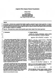
C. Blind Equalization Blind equalization of the transmission channel has drawn achieving equalization without the need of transmitting a training signal. Blind equalization algorithms that have been proposed are the constant modulus algorithm (CMA) and multimodal’s algorithm (MMA). This reduces the meansquared error (MSE) to acceptable levels. Without the aid of training sequences, a blind equalization is used as an adaptive equalization in communication systems. In the blind equalization algorithm, the output of the equalizer is quantized and the quantized output is used to update the coefficients of the equalizer. Then, for the complex signal case, an advanced algorithm was presented in. However, the convergence property of this algorithm is relatively poor.[15] In an effort to overcome the limitations of decision directed equalization, the desired signal is estimated at the receiver using a statistical measure based on a priori symbol properties, this technique is referred to as blind equalization [16]. In the Blind Error is selected as the basis for the filter coefficient update. In general, blind equalization directs the coefficient adaptation process towards the optimal filter parameters even when the initial error rate is large. For best results the error calculation is switched to decision directed method after an initial period of equalization, we call this the shift blind method. Referring to, the Reference Selector selects the Decision Device Output as the input to the error calculation and the Error Selector selects the Standard Error as the basis for the filter coefficient update. 65 | P a g e
http://ijacsa.thesai.org/
(IJACSA) International Journal of Advanced Computer Science and Applications, Vol. 2, No.3, March 2011 TABLE I. FOUR BASIC CLASSES OF ADAPTIVE FILTERING APPLICATION Class of adaptive filtering Identification
Application System identification
Figure8. Blind Equalization
D. Fractionally Spaced Equalizer A fractionally spaced equalizer [17] is a linear equalizer that is similar to a symbol-spaced linear equalizer. By contrast, however, a fractionally spaced equalizer receives say K input samples before it produces one output sample and updates the weights, where K is an integer. In many applications, K is 2. The output sample rate is 1/T, while the input sample rate is K/T. The weight-updating occurs at the output rate, which is the slower rate. Sometimes the input to the equalizer is oversampled such that the sample interval is shorter than the symbol interval and the resulting equalizer is said to be fractionally spaced. Equalizer Taps are spaced closer than the reciprocal of symbol rate. Advantages of FSE are it has ability to be not affected by aliasing problem, shows fast convergence and sample rate is less the symbol rate [18].
Layered earth modeling
Inverse modeling
Prediction
Equalization
Predictive coding
Figure9. Fractional spaced equalizer
V.
APPLICATIONS OF ADAPTIVE FILTERING
The ability of an adaptive filter to operate satisfactorily in an unknown environment and track time variations of input statistics makes the adaptive filter a powerful device for signal processing and control applications. Indeed, adaptive filters have been successfully applied in such devices fields as communications, radar, sonar and biomedical engineering. Although these applications are quite different in nature, nevertheless, they have one basic feature in common: An input vector and a desired response are used to compute an estimation error, which is in turn used to control the values of a set of adjustable filter coefficients. The adjustable coefficients may take the form of tap weights reflection coefficients, or rotation parameters, depending on the filter structure employed. However, the essential difference between the various applications of adaptive filtering arises in the manner in which the desired response is extracted. In this context, we may distinguish four basic classes of adaptive filtering application [1].
Interference cancellation
Spectrum analysis Noise cancellation
Beamforming
Purpose Given an unknown dynamical system, the purpose system identification is to design an adaptive filter that provides an approximation to the system. In exploration seismology, a layered modeled of the earth is developed to unravel the complexities of the earth’s surface. Given a channel of unknown impulse response, the purpose of an adaptive equalizer is to operate on the channel output such that the cascade connection of the channel and the equalizer provides an approximation to an ideal transmission medium. The adaptive prediction is used to develop a model of a signal of interest (e.g., a speech signal); rather than encode the signal directly, in predictive coding the prediction error is encoded for transmission or storage. Typically, the prediction error has a smaller variance than the original signal-Hence the basis for improved encoding. In this application, predictive modeling is used to estimate the power spectrum of a signal of interest. The purpose of an adaptive noise canceller is to subtract noise from a received signal in adaptively controlled manner so as to improve the signal-to-noise ratio. Echo cancellation, experienced on telephone circuits, is a special form of noise cancellation.Noise cancellation is also used in electrocardiography. A beamforming is spatial filter consist of an array of antenna elements with adjustable weights (coefficients). The twin purposes of an adaptive beamformer are to adaptively control the weights so as to cancel interfering signal
66 | P a g e http://ijacsa.thesai.org/
(IJACSA) International Journal of Advanced Computer Science and Applications, Vol. 2, No.3, March 2011 impinging on the array from unknown direction and, at the same time, provide protection to a target signal of interest.
VI.
CONCLUSION
ACKNOWLEDGMENTS The authors would thanks the reviewers for their help in improving the document. REFERENCES
[3] [4]
[5]
[6]
[8]
[9]
The continuing evolution of communication standards and competitive pressure in the market-place dictate that communication system architects must start the engineering design and development cycle while standards are still in a fluid state. Third and future generation communication infrastructure must support multiple modulation formats and air interface standards. FPGAs provide the flexibility to achieve this goal, while simultaneously providing high levels of performance. The SDR implementation of traditionally analog and digital hardware functions opens-up new levels of service quality, channel access flexibility and cost efficiency. In this paper, the several aspects of adaptive equalizer for communication systems are reviewed. Bandwidth-efficient data transmission over telephone and radio channels is made possible by the use of adaptive equalization to compensate for the time dispersion introduced by the channel. Spurred by practical applications, a steady research effort over the last two decades has produced a rich body of literature in adaptive equalization and the related more general fields of reception of digital signals, adaptive filtering, and system identification. There is still more work to be done in adaptive equalization of nonlinearities with memory and in equalizer algorithms for coded modulation systems. However, the emphasis has already shifted from adaptive equalization theory toward the more general theory and applications of adaptive filters, and toward structures and implementation technologies which are uniquely suited to particular applications.
[1] [2]
[7]
Analog and Digital Communications, S.Haykins, Prentice Hall, 1996. Modern Digital and analog Communications system, B.P.Lathi S. U. H. Qureshi, “Adaptive equalization,” Proceedings of the IEEE 1985, vol. 73, no. 9, pp. 1349-1387. B. Petersen, D. Falconer, “Suppression of adjacent-channel, cochannel and intersymbol interference by equalizers and linear combiners,” IEEE Trans on Communication, vol. 42, pp. 3109-3118, Dec. 1994 Adinoyi, S. Al-Semari, A. Zerquine, “Decision feedback equalisation of coded I-Q QPSK in mobile radio environments,” Electron. Lett. vol. 35, No1, pp. 13-14, Jan. 1999. Wang Junfeng, Zhang Bo, “Design of Adaptive Equalizer Based on Variable Step LMS Algorithm,” Proceedings of the Third International Symposium on Computer Science and Computational Technology(ISCSCT ’10) Jiaozuo, P. R. China, 14-15, pp. 256-258, August 2010.
[10]
[11]
[12]
[13]
[14]
[15]
[16]
[17]
[18]
[19]
[20]
[21]
[22]
Antoinette Beasley and Arlene Cole-Rhodes, “Performance of Adaptive Equalizer for QAM signals,” IEEE, Military communications Conference, 2005. MILCOM 2005, Vol.4, pp. 2373 - 2377. En-Fang Sang, Hen-Geul Yeh, “The use of transform domain LMS algorithm to adaptive equalization,” International Conference on Industrial Electronics, Control, and Instrumentation, 1993. Proceedings of the IECON '93, Vol.3, pp.2061-2064, 1993. Kevin Banovic, Raymond Lee, Esam Abdel-Raheem, and Mohammed A. S. Khalid, “Computationally-Efficient Methods for Blind Adaptive Equalization,” 48th Midwest Symposium on Circuits and Systems, Vol.1, pp.341-344, 2005. En-Fang Sang, Hen-Geul Yeh, “The use of transform domain LMS algorithm to adaptive equalization,” International Conference on Industrial Electronics, Control, and Instrumentation, 1993. Proceedings of the IECON '93, Vol.3, pp.2061-2064, 1993. Mahmood Farhan Mosleh, Aseel Hameed AL-Nakkash, “Combination of LMS and RLS Adaptive Equalizer for Selective Fading Channel,” European Journal of Scientific Research ISSN 1450-216X Vol.43, No.1, pp.127-137, 2010. C Chen, C., Chen, K. and Chiueh, T. 2003 “Algorithm and Architecture Design for a low Complexity Adaptive Equalizer,” National Taiwan University, Taipei, Taiwan, 0-7803-7761- 31031S17.0, IEEE. Iliev,G and Kasabov, N. 2000 “Channel Equalization using Adaptive Filtering with Averaging,” 5th Joint coference on Information Science (JCIS), Atlantic city, USA., 2000. Sharma, O., Janyani, V and Sancheti, S. 2009. “Recursive Least Squares Adaptive Filter a better ISI Compensator,” International Journal of Electronics, Circuits and Systems. J Yang, J.-J. Werner, G. A. Dumont, “The multimodal’s blind equalization and its generalized algorithms,” IEEE Journal on selected areas in communication, vol.20, no.5, pp. 997-1015, 2002. 10 D. N. Godard, “Self-recovering equalization and Carrier Tracking in Two-dimensional Data communications Systems,” IEEE Trans. Communication, vol. COM-28, November 1980 J.R. Treichler, I. Fijalkow, and C.R. Johnson, JR., “Fractionally Spaced Equalizers,” IEEE Signal Processing Magazine, Vol.13, Isssue: 3, pp.6581, 1996. Kevin Banovi´c, Mohammed A. S. Khalid and Esam Abdel-Raheem, “A Configurable Fractionally-Spaced Blind Adaptive Equalizer for QAM Demodulators,” Digital Signal Processing, Vol. 17, No.6, pp. 10711088, Nov. 2007. Vladimir D. Orlic, Miroslav Lutovac, “A solution for efficient reduction of intersymbol interference in digital microwave radio,” Telsiks 2009, pp.463-464. Antoinette Beasley and Arlene Cole-Rhodes, “Performance of Adaptive Equalizer for QAM signals,” IEEE, Military Communications Conference, 2005. MILCOM 2005, Vol.4, pp. 2373 - 2377. Haque, A. K. M. F. (2010). Multipath Fading Channel Optimization for Wireless Medical Applications. International Journal of Advanced Computer Science and Applications - IJACSA, 1(4), 33-36. Bappy, D. M., Dey, A. K., & Saha, S. (2010). OFDM System Analysis for reduction of Inter symbol Interference Using the AWGN Channel Platform. International Journal of Advanced Computer Science and Applications - IJACSA, 1(5), 123-125.
AUTHORS PROFILE Garima Malik received her Bachelor of Engineering B.E and pursuing Master of Technology M.Tech from Punjabi University Patiala, India. Amandeep Singh Sappal is currently his Ph.D in Electronic & Communication from Punjabi University Patiala and presently he is working as an Assistant Lecturer in Punjabi University Patiala, India.
67 | P a g e http://ijacsa.thesai.org/