3562
IEEE TRANSACTIONS ON POWER ELECTRONICS, VOL. 32, NO. 5, MAY 2017
A Power Management System for Multianode Benthic Microbial Fuel Cells Ridvan Umaz, Caleb Garrett, Fengyu Qian, Baikun Li, and Lei Wang, Senior Member, IEEE
Abstract—Benthic microbial fuel cells (BMFCs) are important energy-harvesting devices for underwater sensors and electronic devices. However, it is a challenging problem to ensure the robustness of BMFCs in harsh ocean environment. In particular, the anode buried in sediment is subject to burrowing organisms tunneling, which breaks the anaerobic condition, and the electrons generated by the anode will be consumed locally. This eliminates the difference in electric potential between the anode and the cathode. The system then becomes short-circuited and ceases to function. This is a serious problem in the underwater environment due to the likelihood of bioturbation. Using a multianode BMFC can effectively address this problem due to the distributed structure of multiple anodes. This, however, requires a new power management system (PMS) to automatically detect and remove the effect of impaired anodes. This paper presents a new PMS for multianode BMFCs. The proposed PMS automatically disconnects the impaired anodes from the rest of the system for bioturbation resilience and better efficiency. The proposed PMS is self-starting, i.e., no need of extra power sources other than the BMFC. The PMS has been tested through a prototype BFMC. Experimental results demonstrate the effectiveness of this design for multianode BMFCs. Index Terms—Bioturbation, multianode benthic MFC, power management system (PMS), switching circuit.
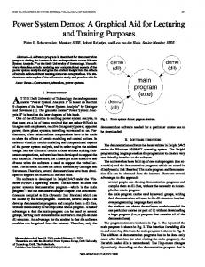
I. INTRODUCTION ENTHIC microbial fuel cells (BMFCs) [1] are devices that exploit the metabolism of aquatic microorganisms to drive electrochemical reactions and harvest electrical energy from organic matter. The basic principle of BMFCs is shown in Fig. 1. Typically, a BMFC consists of an anode buried in sediment and a cathode floating in water [2]. The anaerobic condition is required for microorganisms growing on the anode surface to degrade organic matter and generate electrons. These electrons pass through an external load (e.g., sensors) to reach the cathode, which utilizes dissolved oxygen as electron acceptors. In this manner, BMFCs allow energy harvesting [3] from oceans, lakes, and rivers to support self-sustained operation of underwater
B
Manuscript received May 28, 2015; revised November 24, 2015, March 24, 2016, and June 15, 2016; accepted June 21, 2016. Date of publication June 24, 2016; date of current version February 2, 2017. This work was supported in part by the Office of Naval Research under Grant N000141210345, and in part by the National Science Foundation under CAREER Award CNS 0954037 and CNS 1127084. Recommended for publication by Associate Editor B. Semail. R. Umaz, C. Garrett, F. Qian, and L. Wang are with the Department of Electrical and Computer Engineering, University of Connecticut, Storrs, CT 06268 USA (e-mail:
[email protected];
[email protected];
[email protected];
[email protected]). B. Li is with the Department of Civil and Environmental Engineering, University of Connecticut, Storrs, CT 06268 USA (e-mail:
[email protected]). Color versions of one or more of the figures in this paper are available online at http://ieeexplore.ieee.org. Digital Object Identifier 10.1109/TPEL.2016.2585020
Fig. 1.
Basic principle of benthic MFCs.
sensors and other electronic devices. A well-designed BMFC can operate as long as microorganisms live and require nearly no maintenance. One limiting issue in BMFCs is the relatively low output voltage and power density [4]–[10]. To improve the output voltage and power of BMFCs, some existing techniques rely upon shortening the distance of electrodes [11], applying different cathode arrangements [12], and using multiple independent MFCs [13]. Most of these works rely upon large or parallel electrodes for higher power output. This is because connecting multiple BMFCs in series in open water does not help, i.e., this arrangement is equivalent to a single BMFC setup [2], [5]. Using large electrodes for higher power output, however, makes BMFCs vulnerable to the bioturbation caused by diverse aquatic organisms such as fish digging, which causes a shortcircuit effect in BMFCs. In BMFCs, anodes must be buried under the sediment in order to prevent contact with dissolved oxygen in water. In other words, anodes must be operated under the anaerobic condition, isolated from oxygen. If oxygen seeps into the anode, the electrons generated by the microorganisms at the anode will be consumed by oxygen. These so-called reverse reactions, i.e., electrochemical redox reactions at the anode, eliminate the difference of electric potential between the anode and the cathode. As a result, BMFCs will be short-circuited without any useful voltage and power outputs. BMFCs using a single large anode can be the worst case due to such impairments. Oxygen seep due to burrowing organisms at a small local spot will affect the entire anode and the BFMC will stop functioning.
0885-8993 © 2016 IEEE. Personal use is permitted, but republication/redistribution requires IEEE permission. See http://www.ieee.org/publications standards/publications/rights/index.html for more information.
UMAZ et al.: POWER MANAGEMENT SYSTEM FOR MULTIANODE BENTHIC MICROBIAL FUEL CELLS
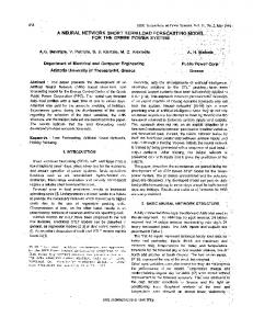
Fig. 2.
Structure of the multianode BMFC developed in [14].
In order to improve the robustness of BMFCs for underwater energy harvesting, bioturbation-related problems must be resolved. For this purpose, our past work developed a distributed multianode BMFC [14], of which the basic structure is shown in Fig. 2. In this BMFC, multiple anodes are spatially distributed and shared by one cathode. If one of the anodes is impaired by burrowing organisms, the problem is confined to that anode only, while the other anodes can continue to operate and the BMFC will maintain a stable power output. The robustness of BMFCs is therefore greatly improved in the harsh marine environment in the presence of diverse bioturbation problems. Employing multiple anodes for bioturbation resilience imposes new requirements on the design of power management systems (PMS). Specifically, the PMS must be able to detect the impaired anodes automatically and disconnect them from the rest of the BMFC; otherwise the reverse reactions at the impaired anodes will cause an equivalent short-circuit effect to other anode/cathode pairs as well. In addition, the PMS should boost the output voltage to a level required by the load. The load will be operated in the burst mode; it requires a certain charging time to accumulate energy into an energy storage element so that the load can work for a short period, and this scenario will be repeated over the time. These new requirements are truly challenging due to the fact that BMFCs typically generate very small output power (e.g., less than 1 w/m2 of electrode area in field tests), which also requires the overhead of the PMS to be as small as possible. Previous works [2], [4]–[9], and [12] have studied several PMS for single-anode BMFCs. In [17], a PMS was developed for multiple independently operated SMFCs (mio-SMFC) to improve the robustness against failures in individual SMFC (e.g., when the anode of an SMFC is not totally covered by the sediment). These PMS are in general not suitable for multianode BMFCs [14]. This paper presents a new PMS design for achieving bioturbation resilience in multianode BMFCs [14], which have a different structure than the multiple independently operated SMFCs [17]. The proposed PMS consists of a multianode decoupling circuit, a super capacitor, a self-sustained (i.e., not requiring other power sources) switching circuit, and a dc–dc converter. The multianode decoupling circuit is a key component in this PMS. It can automatically detect and disconnect the impaired anodes caused by bioturbation, so that the BMFC can reliably harvest energy even if the anaerobic condition at some anodes is broken by aquatic organisms, i.e., seeped oxygen resulting in electron depletion at the corresponding anodes. The super capacitor is used to temporarily accumulate the harvested
3563
energy and then deliver it to the dc–dc converter, which steps up the output voltage for the load. The self-sustained switching circuit provides an interface between the super capacitor and the dc–dc converter. This circuit controls the energy accumulation and delivery processes. Different from most existing PMS for BMFCs, the proposed PMS is self-starting, i.e., no need of extra power sources other than the BMFC. The preliminary idea of this PMS was discussed in [20], whereas this paper presents the detailed design. Experimental results demonstrate that the proposed PMS achieves high efficiency and reliable performance under the bioturbation. The rest of the paper is organized as follows. Section II presents the design of the proposed PMS for multianode BMFCs to deal with bioturbation problems. Section III discusses the implementation of a prototype multianode BMFC and the PMS. Experimental results and evaluation are given in Section IV and the conclusion is drawn in Section V. II. PMS FOR MULTIANODE BMFCS The system diagram of the proposed PMS is shown in Fig. 3. It consists of a multianode decoupling circuit, a super capacitor, a switching circuit, and a dc–dc converter. The function of the multianode decoupling circuit is to remove the effect of impaired anodes so as to improve the robustness of the BMFC under bioturbation. The switching circuit controls the charging– discharging cycles of the super capacitor, which acts as a temporary storage to accumulate the energy harvested from the BMFC. The dc–dc converter generates the required output voltage to the load. Detailed design and operation of these components will be discussed in the following sections. A. Multianode Decoupling Circuit Bioturbation problems cause an equivalent short-circuit effect at the affected anodes. This is because the seeped oxygen causes reverse reactions that consume the harvested electrons at the anode surface, i.e., the electrons will not be transported to the cathode and consumed by the external load. The decoupling circuit is able to detect this problem automatically and disconnect the affected anodes from the rest of the BMFC. As shown in Fig. 4, the decoupling circuit consists of a group of charge pumps, the number of which equals that of the anodes in the BMFC. These charge pumps use the shared cathode as their positive inputs. Each charge pump takes one anode as its negative input (i.e., serves as the ground reference). The outputs of the charge pumps are connected to the super capacitor, which is used as the storage element to accumulate the harvested energy from the BMFC. Assume that one anode is impaired by bioturbation (e.g., seeped oxygen). Due to reverse reactions, the electric potential of this anode will drop and approach the potential of the shared cathode, e.g., this anode is turning into a cathode. Thus, the charge pump taking this anode and the shared cathode as the negative and positive input, respectively, does not have enough input voltage to start up. Other anodes will not be shorted because these anodes are connected to the negative inputs of different charge pumps. The shared cathode will not be affected either because bioturbation only occurs on anodes; nor will the
3564
Fig. 3.
IEEE TRANSACTIONS ON POWER ELECTRONICS, VOL. 32, NO. 5, MAY 2017
System diagram of the proposed PMS.
Fig. 4. Multianode decoupling circuit. A shared cathode is used as the positive input for all charge pumps while each charge pump uses one anode as its own ground. Each charge pump has a local capacitor (C c p i ).
shared output be affected because the impaired anode effectively disables the corresponding charge pump (as there is not enough input voltage to start up this charge pump), i.e., the output of a disabled charge pump cannot be shorted by its inputs because of the internal isolation circuitry in the charge pump [18]. This is also the case if more than one anodes are impaired, where the corresponding charge pumps are also disabled. Note that other unaffected charge pumps are still functioning because their anodes are decoupled from the impaired anodes. Note that each charge pump will need a local capacitor to first accumulate the energy harvested from the corresponding anode. Once the local capacitor reaches or exceeds the discharge start voltage, the positive end of the local capacitor will be connected to that of the super capacitor by a switch circuit inside the charge pump. The negative ends of the local capacitor and the super capacitor (using an anode as the ground reference) are not physically connected but have similar electric field potential, i.e., they share the same electrical ground. This is because microbes are able to maintain the redox gradients in the sediment and establish a stable electric field potential at the anodes [14]– [16]. Thus, the harvested energy by the other anodes will be transferred from their local capacitors to the super capacitor. A question arises that, instead of using individual local capacitor for each charge pump, whether it is possible to use only one local capacitor shared by all charge pumps. The answer is no due to two reasons. First, since anodes may be surrounded by different sediment conditions, the charge pumps will have different charging and discharging cycles. It is impossible to synchronize these operations for a single local capacitor. Second, these charge pumps are also used to detect bioturbation problems on the anodes. If one or several anodes are impaired, the corresponding local capacitors will have no or very small voltage. Thus, the total output voltage of the decoupling circuit will be reduced if all local capacitors are replaced by a shared local capacitor. The value of the local capacitors affects the time of transferring the stored energy to the load, which is critical to the BMFC that may have impaired anodes. In other words, if one or some anodes are impaired, the energy stored in their local capacitors is
no longer retrievable because these capacitors may not reach the discharge start voltage required by the charge pumps. In order to determine the optimal value of the local capacitors, the power transfer efficiency of the charge pumps should be considered. This efficiency is defined as the ratio between the input power Pin of a charge pump and the received power Pc at its local capacitor, as η = Pc /Pin .
(1)
The charge pump input power Pin can be calculated as Pin = Vin × Iin
(2)
where Vin and Iin are the average input voltage and current (drawn from the BMFC), respectively, of the charge pump. On the other hand, the charge pump starts to discharge the local capacitor to the super capacitor once its local capacitor voltage reaches the discharge start voltage Vd , and the discharging process stops when the local capacitor voltage reduces to Vc , at which point the local capacitor starts to charge up again by the BMFC. Thus, the energy delivered to the local capacitor can be expressed as E = 1/2 × C × (Vd2 − Vc2 )
(3)
where C is the value of the local capacitor. The average power Pc delivered to the local capacitor can be obtained as Pc = (1/2t) × C × (Vd2 − Vc2 )
(4)
where t is the time for the local capacitor to charge from Vc to Vd . In this study, Vd and Vc are 2 and 1.44 V , respectively, while the charging time t increases nonlinearly with C (the underlying effect will not be cancelled out by C/t). Thus, if a large local capacitor is used, it will increase the take a long time to charge this capacitor, which will reduce the charge pump output power Pc as well as the power transfer efficiency η. In this paper, different local capacitors are tested and the corresponding power transfer efficiencies are measured to determine the optimal capacitor value that maximizes η, as discussed in Section III.
UMAZ et al.: POWER MANAGEMENT SYSTEM FOR MULTIANODE BENTHIC MICROBIAL FUEL CELLS
Fig. 6.
Fig. 5. Characteristic curve of the switching circuit. During the charging process, the switch is OFF, while during the discharging process, the switch is ON.
B. Super Capacitor and Switching Circuit As mentioned, the charge pumps in the decoupling circuit cannot be synchronized on their charging and discharging cycles, which are determined by the sediment conditions around the anodes. When a charge pump’s local capacitor reaches the discharge start voltage, the stored energy is released through the output of the charge pump. Because the discharging times of these charge pumps are different, the outputs of the charge pumps cannot drive the dc–dc converter or the load directly. Doing so will significantly reduce the efficiency of the PMS. The best solution to this problem is to incorporate a super capacitor, which acts as the second stage storage to accumulate the energy when any of the charge pumps start to discharge. Note that the outputs of nonfunctional charge pumps (e.g., those connected to the impaired anodes) are high-impedance and thus will not affect the operation of the super capacitor. Due to the buffering effect of the super capacitor, a relatively stable energy level is available for the subsequent circuits. The connection between the super capacitor and the dc–dc converter needs to be controlled by a switching circuit. If no switching circuit exists, the dc–dc converter will constantly draw current from the super capacitor. Due to the low output power of BMFCs, the super capacitor voltage will drop quickly and would not come back again to the required level of the dc–dc converter. Thus, the dc–dc converter is not able to start up and drive the load. As shown in Fig. 5, the desired operation of the switching circuit should be as follows. 1) Initially, the super capacitor starts to charge from 0. The switching circuit is OFF, and the support capacitor and the dc–dc converter are disconnected. The input voltage of the dc–dc converter is zero during this period. No power is delivered to the load. 2) When the super capacitor reaches the discharge start voltage Vd , the switching circuit turns ON and connects the super capacitor to the dc–dc converter. The input voltage of the dc–dc converter is equal to the voltage of the super capacitor. The super capacitor starts to transfer the stored
3565
Schematic of the switching circuit.
energy to the dc–dc converter, which then provides the power to the load with the required voltage level. 3) Due to the low power output of BMFCs, the dc–dc converter draws energy from the super capacitor at a faster rate than the super capacitor draws energy from the charge pumps. Thus, the voltage of the super capacitor starts to reduce immediately after it is connected to the dc–dc converter by the switching circuit. When the voltage drops to the charge start voltage Vc , the switching circuit turns OFF, disconnecting the super capacitor from the dc–dc converter. The input voltage of the dc–dc converter becomes zero and the load receives no power. 4) The super capacitor starts to charge back from Vc to Vd by the BMFC through the charge pumps, and the operation returns to step 2. Note that the above operations can be implemented in different ways. For example, a hysteresis controller [8], [9] could be utilized, but an extra power supply is needed to power the comparator and build reference voltages. Using extra power supplies to enable power management functions is undesirable as it compromises the goal for self-sustainability. Ideally, the entire system, including the PMS and the load, should be powered by the BMFC only. In this paper, we develop a new switching circuit that is self-starting, i.e., it does not require any extra power sources other than the energy harvested by the BMFC. Fig. 6 shows the schematic of the proposed switching circuit. As the super capacitor initially charges up, the pMOS transistor P 1 is cut off. The voltage of the super capacitor goes through P ath1 across the diodes D1 and D2 and nMOS transistor N 1. The gate voltage Vg 2 of the nMOS transistor N 2 can be expressed as Vg 2 = VCAP − 2 × VD − Vtn 1
(5)
where VCAP is the voltage of the super capacitor that is being charged up, VD is voltage drop over the diode, and Vtn 1 is the threshold voltage of the nMOS transistor N 1. Once Vg 2 increases above the threshold voltage Vtn 2 of N 2, N 2 becomes conducting and the gate voltages of the pMOS transistors P 1 and P 2 drop to zero. Consequently, P 1 and P 2 turn ON and the dc–dc converter is connected to the super capacitor through P 2. The super capacitor starts to discharge and transfer the stored energy to the dc–dc converter. Substituting Vg 2 = Vtn 2 into (5), the super capacitor’s discharge start voltage Vd can be expressed as Vd = Vtn 1 + Vtn 2 + 2 × VD .
(6)
3566
IEEE TRANSACTIONS ON POWER ELECTRONICS, VOL. 32, NO. 5, MAY 2017
TABLE I CHARGING TIME AND POWER TRANSFER RATIO FOR DIFFERENT CHARGE PUMP LOCAL CAPACITORS Capacitor C c p (μF) 470 800 1270 1740 2210
Fig. 7.
Prototype BMFC with four anodes and one shared cathode.
As diode D1 is bypassed by P 1 on P ath2, and the gate voltage Vg 2 of N 2 initially undergoes a sudden increase with the amount equal to the voltage drop of D1, i.e., Vg 2 = VCAP − VD − Vtn 1 .
(7)
This increase will keep N 2 on until the voltage of the super capacitor VCAP drops to the charge start voltage Vc . From (7), as the voltage of the super capacitor VCAP drops, Vg 2 reduces as well. Once Vg 2 reaches the threshold voltage Vtn 2 of N 2, N 2 is cut off, which also turns OFFP 1 and P 2 and thus disconnects the dc–dc converter from the super capacitor. The super capacitor will be charged again. Thus, substituting Vg 2 = Vtn 2 into (7), the charge start voltage Vc can be expressed as Vc = Vtn 1 + Vtn 2 + VD .
(8)
Obviously, the above operations are controlled by the output voltage of the super capacitor only, i.e., the proposed switching circuit is self-starting (no need of extra power sources). In addition, the charge pumps and the dc–dc converter are also self-starting, making the proposed PMS highly efficient and self-sustainable. III. IMPLEMENTATION The proposed PMS was implemented in a printed circuit board (PCB) and tested through a prototype BMFC. The BMFC has four anodes and one shared cathode to deal with the bioturbation problems. A. Multianode BMFC A multianode BMFC made from plexiglas cylinders (effective working volume: 500 mL, inner diameter: 7.5 cm, and length: 15 cm) was used to test the performance of the proposed PMS. The BMFC implementation is shown in Fig. 7. Four carbon cloth anodes are placed inside the plexiglas cylinder and buried
Charging Time (s)
Power Ratio η (%)
32 53 80 112 142
31 31.04 31.08 29.81 29.09
in the sediment to support the growth of microorganisms and collect the generated electrons. Each of the installed anodes is separated by 2 cm in distance. Three anodes are used for energy harvesting and one anode serves as the ground reference for the super capacitor, switching circuit, dc–dc converter and the load. Activated carbon cathode (diameter: 5 cm) and 20% polytetrafluoroethylene is secured onto the plexiglas cylinder and immersed in water to utilize the dissolved oxygen as the electron acceptor. The cathode is positioned parallel to the benthic surface at a distance of 4 cm. The water depth above the cathode is 12 cm. Organic soil sediments with diverse microbes are utilized as the inocula. Sodium acetate is added as an additional carbon source to enhance the inoculation of anaerobic electrogenic bacteria. All measurements were conducted in duplicates and operated at room temperature of 20 ◦ C. B. PMS Implementation The charge pumps for the BMFC need to work with a low input voltage and draw small current from the BMFC. The charge pump S-882 from Seiko Instruments [18] was selected. It requires an input voltage as low as 0.3 V and can charge to 2 V and discharge to 1.44 V. The decoupling circuit uses three charge pumps, each connected to one anode. Each S-882 charge pump requires an external local capacitor Ccp , whose value must be large enough to support the charge sharing between the charge pump and the super capacitor/dc– dc converter when the switching circuit is ON. In addition to this requirement, the selection of the local capacitor Ccp also affects the power transfer efficiency η, as discussed in Section II-A. To obtain the optimal power transfer efficiency, different values of Ccp were tested, and the input and output power of the charge pump was measured to calculate the efficiency. Table I shows the results of charging time and power transfer ratio η (measured from one charge pump) under different values of Ccp . The charging time refers to the time when the capacitor voltage increases from 1.44 to 2 V. From Table I, it can be seen that using a larger charge pump capacitor results in a longer charging time. Moreover, the power transfer efficiency also changes, initially increasing and then decreasing. This is because power transfer is a complicated process determined by the electric operating mode of the charge pump, which in this case varies with the size of the local capacitor Ccp . The largest value of power transfer efficiency is achieved when Ccp = 1270 μF. As the value of Ccp increases, the effect of increase in charging time will dominate and reduce the
UMAZ et al.: POWER MANAGEMENT SYSTEM FOR MULTIANODE BENTHIC MICROBIAL FUEL CELLS
power transfer efficiency. If one or more anodes fail to operate due to bioturbation or other problems, the stored energy in the corresponding Ccp will be unaccessible because the capacitor cannot reach the required voltage level to discharge the charge pump. The stored energy will then be trapped in the capacitor. This problem can be mitigated by using a smaller charge pump capacitor to reduce the charging time. As the charging time is reduced, the amount of wasted energy, if any, will be relatively small. In this design, we choose Ccp = 470 μF because of the short charging time. Also, the degradation in power transfer efficiency is negligible. Using a smaller charge pump capacitor reduces the charging time of the charge pump, which minimizes the impact of bioturbation on anodes. The selection of the super capacitor needs to consider the requirement of specific applications (e.g., the power requirement of loads). For the purpose of demonstration, we use a 220 mF super capacitor with the discharge start voltage Vd = 1.44 V and the charge start voltage Vc = 1.12 V. The reason of choosing Vd = 1.44 V is that this value is the maximum voltage allowed by the super capacitor. On the other hand, choosing Vc = 1.12 V enables the dc–dc converter (here we choose L6920DB from ST microelectronics [19]) to achieve a higher efficiency than the specified minimum input voltage of 0.8 V. The switching circuit needs to be operated with these voltages; i.e., the switch will be ON to discharge the super capacitor when the super capacitor voltage reaches Vd = 1.44 V, and when the super capacitor voltage drops to Vc = 1.12 V, the switch will be OFFso that the super capacitor can be recharged by the BMFC. In Fig. 6, the diodes D1 and D2 are 1N4001 and 1N4004 (Vishay Siliconix, VD = 320 mV), respectively, P 1 is FDN304P (Fairchild semiconductor, Vtp1 = −0.4 V), P 2 is Si3499DV (Vishay Siliconix, Vtp2 = −0.75 V), N 1 is PMV31XN (NXP semiconductors, Vtn 1 = 0.35 V), and N 2 is Si3460BDV (Vishay Siliconix, Vtn 2 = 0.45 V). Thus, Vd = 1.44 V and Vc = 1.12 V from (6) and (8) in Section II-B, which meet the design specifications. Note that the charge start voltage Vc and the discharge start voltage Vd can be adjusted by applying different types of diodes or adding more diodes to the switching circuit. The fabricated PCB of the PMS is shown in Fig. 8. IV. EXPERIMENTAL RESULTS AND DISCUSSION This section presents the experimental results from the proposed PMS and the BMFC. The power–current density characteristics of the BMFC were tested as follows. First, the BMFC was connected to a resistive load until it reached the steady state. After that, the load was disconnected to measure the BMFC open circuit voltage, which was around 0.45 V in this study. Then, a variable resistive load (Rext ) from 15 to 2500 Ω was connected to the BMFC in order to construct the polarization curves for three different anode configurations: a three-anode case (A3 ) where all anodes are functional without any bioturbation, a two-anode case (A2 ) where one anode is impaired by exposing to the dissolved oxygen in water, and a one-anode case (A1 ) where two anodes are impaired for the same reason. For each Rext value, the BMFC output voltage and current values
Fig. 8.
3567
PCB implementation of the PMS.
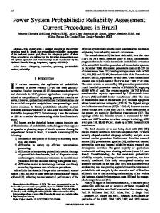
were recorded. The measurements were made when the voltage and the current become stable. In Fig. 9(a), the current density (normalized by the cathode area) and voltage are proportional to the number of functional anodes under the same Rext value. This is because these results are obtained under the different numbers of anodes, i.e., the BMFC has different configurations. The power density was calculated as a product of the measured voltage and current. In Fig. 9(b), it can be seen that the power and current densities increase with the number of functional anodes in the BMFC. These results verify that the multianode BMFC works as expected in the presence of bioturbation. To test the PMS, the BMFC was connected as the input and a 10 kΩ load resistor was connected as the output. Charge pumps were monitored to evaluate the local capacitor charging and discharging cycles for each case, as shown in Fig. 10, where t1 measures the time when the charge pump starts to charge its local capacitor from 0 to 2 V, and t2 is the time that the charge pump charges its local capacitor from the charge start voltage (Vc ) to the discharge start voltage (Vd ). The values of Vc and Vd are 1.44 and 2 V, respectively. For A3 , A2 , and A1 cases, the local capacitors have the same Vc and Vd but different t1 and t2 values, as the number of functional anodes is different and each anode may see different sediment conditions. These results are summarized in Table II, where for A3 and A2 cases, the values of t1 and t2 are averaged over all the functional anodes. To verify the function of the switching circuit, Fig. 11 shows the relationship between the dc–dc converter output voltage and the gate voltage Vg of the PMOS P 2 in Fig. 6, which controls the ON/OFFbehavior of the switching circuit. It can be seen that when the super capacitor voltage reaches the discharge start voltage, Vg starts to decrease and quickly drops to zero (as NMOS N 2 is ON). Thus, P 2 switches ON and the super capacitor starts to discharge. The stored energy at the super capacitor is transferred to the dc–dc converter, which generates a stable 3.3 V output voltage to drive the load. When the super capacitor is discharged to the charge start voltage, P 2 switches OFFand Vg starts to increase. The dc–dc converter output voltage drops
3568
IEEE TRANSACTIONS ON POWER ELECTRONICS, VOL. 32, NO. 5, MAY 2017
Fig. 9. Voltage–current density and power density–current density characteristics of the prototype BMFC. (a) Polarization curve (voltage versus current density). (b) Power density versus current density.
Fig. 10. Measured waveform of charge pump capacitor voltage. The values of time axis (e.g., t1 and t2 ) are different for different cases, as shown in Table II. TABLE II MEASURED TIME RESULTS FOR A 3 , A 2 , AND A 1 CASES Cases A1 A2 A3
t1
t2
t3
t4
t5
202 s 189 s 180 s
60 s 53 s 55 s
4.1 h 2.06 h 1.383 h
25 s 25 s 25 s
0.916 h 0.48 h 0.3 h
to zero as the switching circuit is OFF. The same process repeats over the time. These results indicate that the switching circuit works properly and the expected control on energy transfer is accomplished. The super capacitor voltage and the output voltage to the load were measured in Fig. 12(a), and (b) shows the zoomed area between t3 and t5. For A3 , A2 , and A1 cases, the charge and discharge start voltages of the super capacitor are Vc = 1.12 V and Vd = 1.44 V, respectively. The output voltage to the load is Vout = 3.3 V. It can be seen that when the super capacitor voltage reaches the discharge start voltage Vd = 1.44 V, the switching circuit is ON and the load receives the power from the dc–dc converter. The super capacitor voltage then reduces and once it reaches Vc = 1.12 V, the switching circuit is OFF. No power is delivered to the load and the super capacitor is charged
Fig. 11. Measured waveforms of dc–dc converter output voltage (V o u t ) and the gate voltage (V g ) of PMOS P 2 in the switching circuit. The value of time axis are different for different cases, as shown in Table II.
back by the BMFC through the charge pumps. Due to the low power output of the BMFC [see Fig. 9(b)], the load will operate in this burst mode. It requires a sufficiently long charging time t5 to accumulate the harvested energy into the super capacitor so that the load can consume the energy and work for a short period of t4 . This pattern will be repeated over the time. Note that A3 , A2 , and A1 cases have different values of t3 (initial charging time) and t5 , as shown in Table II. Increasing the number of anodes in the BMFC can reduce both t3 and t5 . This is because multianode BMFCs can harvest more energy to the load. On the other hand, the load active time t4 is the same as the value of the super capacitor is fixed, i.e., the same amount of energy stored in the super capacitor is transferred to the load. Finally, the power transfer efficiencies of A3 , A2 , and A1 cases were measured. The overall efficiency of the system is expressed as ηoverall = η1 ∗ η2
(9)
where η2 is the efficiency of the dc–dc converter, and η1 is the efficiency from the BMFC to the super capacitor, obtained as η1 = Pcc /Pin
(10)
UMAZ et al.: POWER MANAGEMENT SYSTEM FOR MULTIANODE BENTHIC MICROBIAL FUEL CELLS
3569
Fig. 12. (a) Measured waveforms of the super capacitor voltage (V C A P ) and the output voltage to the load (V o u t ). (b) Zoomed waveforms when the load is active (e.g., between t3 and t5 in (a)). The values of time axis (e.g., t3 , t4 , t5 ) are different for different cases, as shown in Table II. TABLE III PERFORMANCE COMPARISON OF THE EXISTING PMS Circuit # of anode # of cathode Required startup voltage External power sources Efficiency Bioturbation/Robutsness
[5]
[6]
[8]
[17]
This paper
Single Single 300 mV Not required 22% No
Single Single 180 mV Not required N/A No
Single Single N/A Required for operation 45% No
Multi Multi 300 mV Not required 32.8% Yes
Multi single 300 mV Not required 35.02% Yes
where Pin is the charge pump input power (i.e., BMFC output power) and Pcc is the power transferred to the super capacitor, defined as Pcc = (1/2t5 ) × C × (Vd2 − Vc2 )
(11)
where C is the value of the super capacitor. As an off-the-shelf charge pump (Seiko S-882) is used, its input impedance is fixed, which is larger than the BMFC internal impedance. As a result, the input power to the charge pump is smaller than the maximum output power of the BMFC. This affects the charging and discharging cycles of the charge pump, resulting in a long charging time t5 . As the number of functional anodes increases, the charging time t5 reduces and Pcc increases, which increases the overall efficiency. The overall power transfer efficiencies are 20.23%, 26.18%, and 35.02% for A1 , A2 , and A3 , respectively. Note that most losses during power transfer come from the overheads in the commercial charge pump, dc– dc converter and other components used in PMS, which are beyond our control. Table III compares the existing works of PMSs for MFCs. In terms of efficiency, the proposed PMS is comparable to the previous work [17] that does not require the support of external power sources. Note that this paper and [17] target different MFC structures and apply different approaches for power management. In summary, the proposed PMS is truly self-sustainable and can effectively address the bioturbation problem.
V. CONCLUSION Multianode BMFCs have distinct advantages over the existing single-anode BMFCs. Using multiple anodes can improve the robustness of BMFCs in the harsh ocean environment. A PMS for multianode BMFCs was developed in this paper. The PMS is self-starting and can automatically detect the impaired anodes due to bioturbation. Design optimization of the PMS includes the consideration of both the power transfer efficiency and the impact of possible bioturbation problems. The detailed design of the PMS was discussed and the performance was tested with a prototype multianode BMFC. The experimental results match with the design specifications. Further work is directed toward field tests and further system optimization to improve the power transfer efficiency of the PMS.
REFERENCES [1] N. Degrenne et al., “Self-starting DC:DC boost converter for low-power and low-voltage microbial electric generators,” in Proc. IEEE Energy Convers. Congr. Expo., 2011, pp. 889–896. [2] C. Donovan, A. Dewan, H. Peng, D. Heo, and H. Beyenal, “Power management system for a 2.5 W remote sensor powered by a sediment microbial fuel cell,” J. Power Sources, vol. 196, pp. 1171–1177, Feb. 2011. [3] L. M. Tender et al., “Harnessing microbially generated power on the seafloor,” Nature Biotechnol., vol. 20, pp. 821, Aug. 2002. [4] C. Donovan, A. Dewan, D. Heo, and H. Beyenal, “Batteryless, Wireless sensor powered by a sediment microbial fuel cell,” Environ. Sci. Technol., vol. 42, no. 22, 2008, pp. 8591–8596. [5] A. Meehan, H. Gao, and Z. Lewandowski, “Energy harvesting with microbial fuel cell and power management system,” IEEE Trans. Power Electron., vol. 26, no. 1, pp. 176–181, Jan. 2011.
3570
IEEE TRANSACTIONS ON POWER ELECTRONICS, VOL. 32, NO. 5, MAY 2017
[6] F. Yang, D. Zhang, T. Shimotori, K. Wang, and Y. Huang, “Study of transformer-based power management system and its performance optimization for microbial fuel cells,” J. Power Sources, vol. 205, pp. 86–92, May 2012. [7] D. Zhangb, F. Yanga, T. Shimotoric, K. Wanga, and Y. Huangd, “Performance evaluation of power management systems in microbial fuel cellbased energy harvesting applications for driving small electronic devices,” J. Power Sources, vol. 217, pp. 65–71, Nov. 2012. [8] J. Park and Z. Ren, “Hysteresis-controller-based energy harvesting scheme for microbial fuel cells with parallel operation capability,” IEEE Trans. Energy Convers., vol. 27, no. 3, pp. 715–724, Sep. 2012. [9] J. Park and Z. Ren, “High efficiency energy harvesting from microbial fuel cells using a synchronous boost converter,” J. Power Sources, vol. 208, pp. 322–327, Jun. 2012. [10] P. K. Wua, J. C. Biffingerb, L. A. Fitzgeraldb, and B. R. Ringeisen, “A low power DC/DC booster circuit design for microbial fuel cell,” Process Biochem., vol. 47, no. 11, pp. 1620–1626, Nov. 2012. [11] J. Dai, X. Li, B. Li, and L. Wang, “Design and modeling of an underwater energy harvesting system,” in Proc. Int. Symp. Circuits Syst., pp. 22–26, 2011. [12] F. Zhang, L. Tian, and Z. He, “Powering a wireless temperature sensor using sediment microbial fuel cells with vertical arrangement of electrodes,” J. Power Sources, vol. 196, pp. 9568–9573, 2011. [13] T. Ewing, P. Ha, J. Babauta, N. Tang, D. Heo, and H. Beyenal, “Scale-up of sediment microbial fuel cells,” J. Power Sources, vol. 272, pp. 311–319, 2014. [14] U. Karra, G. Huang, R. Umaz, C. Tenaglier, L. Wang, and B. Li, “Stability characterization and modeling of robust distributed benthic microbial fuel cell (DBMFC) system,” Elsevier Bioresource Technol., vol. 144, pp. 477–484, Sep. 2013. [15] K. Rabaey and W. Verstaete, “Microbial fuel cells: Novel biotechnology for energy generation,” Trends Biotechnol., vol. 23, no. 6, pp. 291–298, 2005. [16] F. Rezaei, T. L. Richard, R. A. Brennan, and B. E. Logan, “Substrate enhanced microbial fuel cells for improved remote power generation from dediment-based systems,” Environ. Sci. Technol., vol. 11, pp. 4053–4058, 2007. [17] N. Tang, W. Hong, T. Ewing, H. Beyenal, J. H. Kim, and D. Heo, “A self-sustainable power management system for reliable power scaling up of sediment microbial fuel cells,” IEEE Trans. Power Electron., vol. 30, no. 9, pp. 4626–4632, Sep. 2015. [18] Seiko Instruments Inc., “Ultra low voltage operation charge pump IC for step UP DC-DC converter startup,” Chiba, Japan, S882Z Datasheet, 2010. [19] STMicroelectronics, “Synchronous rectifier step up converter,” Geneva, Switzerland, L6920DB Datasheet, Oct. 2006. [20] U. Karra, E. Muto, R. Umaz, M. Kolln, C. Santoro, L. Wang, and B. Li., “Performance evaluation of activated carbon-based electrodes and novel power management system for long-term benthic microbial fuel cells,” Int. J. Hydrogen Energy, vol. 36, pp. 21847–21856, Dec. 2014.
Ridvan Umaz received the B.Sc. degree in electrical and electronics engineering from Inonu University, Malatya, Turkey, in 2009, and the M.S. degree in electrical and computer engineering from University of Connecticut, Storrs, CT, USA, in 2013, where he is currently working toward the Ph.D. degree in electrical and computer engineering. His research interests include energy harvesting system, integrated circuit design, low power charge pumps and dc–dc converters. Caleb Garett received the B.S. degree in electrical engineering from the University of Connecticut, Storrs, CT, USA, in 2016. He is currently employed at the Whelen Engineering in Chester, CT as an Electronic Design Engineer. His research interests include vehicle-to-vehicle communication and wireless connectivity for the Internet of Things.
Fengyu Qian received the B.S. degree in electronics science and technology, from the Xian Jiaotong University, Xi’an, China, in 2012. He is currently working toward the Ph.D. degree in electrical and computer engineering from the University of Connecticut, Storrs, CT, USA. His research interests include very-large-scale integration (VLSI) circuit design, VLSI signal processing, renewable energy power management, and smarts sensors such as on-chip sensors and biosensors.
Baikun Li received the B.Eng. and M.Eng. degrees from Harbin Institute of Technology, Harbin, China, and the Ph.D. degree from University of Cincinnati, Cincinnati, OH, USA, in 1992 1995, and 2002, respectively. She completed the post-doctorate training at the Pennsylvania State University in 2003. She was the Assistant Professor at Penn State Harrisburg for three years before moving to UConn in 2006. She is the Professor of environmental engineering at the University of Connecticut, Storrs, CT, USA. Her research interests include multidisciplinary areas of bioenergy production from wastes, bioelectricity harvest from ocean sediment, and biosensors and bioelectronics. Her current research focuses on the development of self-sustained wastewater treatment processes; optimization of biomass energy production from waste treatment; scale-up underwater electricity harvest systems; real time in situ environmental shock sensing; and long-term on-line wastewater quality monitoring. Dr. Li received the Al Geib Professorship and the Woman of Innovation (Research Innovation and Leadership) award in 2010 by the Connecticut Technology Council. She has served as the Associate Editor for Journal of Environmental Engineering (ASCE) and CLEAN-Soil, Air, Water. She has been the major adviser for more than 30 graduate students.
Lei Wang (M’01–SM’11) received the B.Eng. and M.Eng. degrees from Tsinghua University, Beijing, China, and the Ph.D. degree from the University of Illinois at Urbana-Champaign, Champaign, IL, USA, in 1992, 1996, and 2001, respectively. During the summer of 1999, he worked at Microprocessor Research Laboratories, Intel Corporation, in Hillsboro, OR, USA, where his work involved development of high-speed and noise-tolerant VLSI circuits and design methodologies. From December 2001 to July 2004, he was with Microprocessor Technology Laboratories, Hewlett-Packard Company, Fort Collins, CO, USA, where he participated in the design of the first dual-core multi-threaded Itanium Architecture Processor, a joint project between Intel and Hewlett-Packard. Since August 2004, he has been with the Department of Electrical and Computer Engineering, University of Connecticut, Storrs, CT, USA, where he is currently the F. L. Castleman Associate Professor in Engineering Innovation. Dr. Wang received the National Science Foundation CAREER Award. He is the Member of IEEE Signal Processing Society Technical Committee on Design and Implementation of Signal Processing Systems. Since 2014, he has been serving as a Senior Area Editor for the IEEE SIGNAL PROCESSING LETTERS, and on the Steering Committee of the IEEE TRANSACTIONS ON MULTI-SCALE COMPUTING SYSTEMS. He served as an Associate Editor for the IEEE TRANSACTIONS ON COMPUTERS from 2010 to 2014, and an Associate Editor for the IEEE SIGNAL PROCESSING LETTERS from 2012 to 2014. He has served on Technical Program Committees of various international conferences.