Development of a Multicore Power System Simulator for Ship Systems Fabian M. Uriarte
Robert Hebner
Center for Electromechanics The University of Texas at Austin Austin, TX, USA
[email protected]
Center for Electromechanics The University of Texas at Austin Austin, TX, USA
[email protected]
Abstract—An important impediment to using widely available software to simulate the behavior of advanced power systems for electric ships is that the simulation time is too long to be practical. Consequently, the Center for Electromechanics at the University of Texas at Austin (UT-CEM) is developing a multicore power system solver to simulate large shipboard power systems. In its first year of development, the focus is on testing CEM’s solver (CEMS) for accuracy. This paper presents an overview of the major traits of CEMS, and compares its simulation results to the well-known commercial power system simulator SimPowerSystems. Preliminary results show that accuracy is maintained and improved in specific test cases.
in commercial power system simulators [1],[2] is well known throughout the Navy and its shipyards.
I.
While efforts to speed-up the simulation time of shipboard power systems models are not new, they are not widely available or come at a cost. For example, in [3], the latency insertion method was used to partition a large, notional electric shipboard power system into subsystems. Although speed gains of 14x were report on a multicore computer, VTB [4] is required as the user-interface. The current approach is to try to achieve the same acceleration using more conventional interfaces to reduce training costs. An additional widely known solver is Opal-RT’s ARTEMIS [5], currently capable of importing SimPowerSystems schematics and solving large shipboard power systems in real-time when using their target hardware. A solution as such, however, would require the acquisition of costly specialized hardware and would not be accessible to other members of the ship research community. Power system models in the ship community already exist in SimPowerSystems or PSCAD [2], and remaining in such environments reduces training costs.
INTRODUCTION
As the all-electric ship program continues to progress from the conceptual stage toward practical implementation, the need for accurate modeling and simulation of its electrical power system has become more apparent. The large assortment of loads encountered on a warship, ranging from continuous duty loads to highly intermittent duty loads, makes it imperative to understand how the loads can be integrated in the shipboard power system and how they will interact dynamically with each other, as well as with the available power sources. Furthermore, the increased presence of power electronic stages, especially at the interface between the ac and dc zones of the system, requires more stringent control methods, both at the local and global level, thus adding to the complexity of the system.
This paper presents an overview of UT-CEM’s effort to develop fast power system simulations for Navy entities: a multicore power system solver called CEMS. Two traits make CEMS highly attractive: compatibility and speed potential. Compatibility comes from using SimPowerSystems as the user interface, which will allow users to retain existing models and solve them in CEMS. Speed is sought via power system partitioning and proper exploitation of multicore technology, which is now available on desktop computers.
Under the sponsorship of the Office of Naval Research, researchers at the University of Texas Center for Electromechanics (UT-CEM) have made an attempt to model a notional electric ship with a collection of different loads . This effort resulted in the development of a relatively large power system model, using SimPowerSystems [1], for a ship system supporting several load types. Although the effort produced usable and interesting results, the large power system model highlighted a major challenge: even under the assumption of a simplified architecture, the power system complexity poses strong computational demands on desktop computers, which results in unbearably long simulation run-times. In fact, it was not unusual to wait one week for calculations covering only six seconds of simulated data. This issue involving execution time
Section II presents traits that make CEMS an attractive solver. Section III presents major tiers internal to the solver under development. Section IV presents case studies to demonstrate the solver’s accuracy in specific cases. II.
This work is sponsored by the Office of Naval Research as part of the Electric Ship Research and Development Consortium.
978-1-4244-9273-2/11/$26.00 ©2011 IEEE
MOTIVATION
Compatibility and speed are of primary concern, to UTCEM. These characteristics have been deemed necessary to increase the wide spread impact of CEMS. An overview of these two traits follows
106
A. Compatiblity The life span of a program is strongly dependant on its usability. For this reason, UT-CEM decided to shun the development of a graphical user interface (GUI) for CEMS, and instead use the familiar SimPowerSystems as its GUI [6]. Use of an existing GUI circumvents several issues of new interface designs: development, maintenance, support, documentation, training, and porting existing models. These issues unnecessarily demand an exorbitant amount of staffyears.
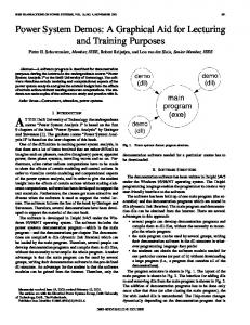
Figure 2. Partitioning method implemented by CEMS. Current sources are torn at the disconnection point shown.
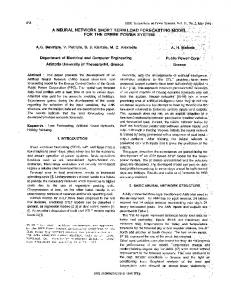
Integration between SimPowerSystems and CEMS is depicted in Figure 1. After creating or opening SimPowerSystems models (.MDL file), users are currently able to solve select models as normal in Simulinnk—or—launch CEMS (.EXE file), import the .MDL file, and execute the simulation externally. Since CEMS is intended for large power system models only, users will be advised to simulate small models as normal. The simulation data produced by CEMS is in the form of .CSV files which can be plotted from most visualization environments. SimPowerSystems (.MDL file)
CEMS (.EXE file)
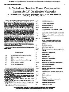
Development of CEMS follows the spiral design approach depicted in Figure 3. Each stage is entered as the previous stage reaches satisfactory completion. This cycle is currently in effect and will continue until CEMS is available. As exemplified with case studies later, this paper is the result of the first accuracy assessment. Subsequent work by the authors will become available as CEMS progresses through the design cycle. Development
Results (.CSV files)
Figure 1. CEMS imports SimPowerSystems models and solves outside of the Simulink enviromment. The results are output in .CSV files.
Speed
Accuracy
Figure 3. Software design cycle. As phases reach acceptable completion, the next phase is visited in clockwise order.
B. Speed Several things are responsible for lengthy simulations, including single matrix formulations, system order, switch model, integration step size, programming efficiency, etc. These are software-based and controllable in the sense that their impact can be mitigated at a relatively low cost.
III.
PROGRAM TIERS
CEMS executes several tiers before starting a simulation. Among these tiers, the major ones are discretization, partitioning, and simulation methodology.
Because software-based reasons can be addressed at a relatively low cost, UT-CEM has embarked on the development of a multicore power system simulation solver named CEMS. The partitioning approach used by CEMS addresses the issue of single-matrix formulationns which do not use the many cores available on desktop computers.
Discretization in CEMS is based on root-matching [13] instead of trapezoidal integration. This choice stems from the fact that root-matching is not as sensitive to numerical chatter as is the trapezoidal rule [14],[15]. Although backward Euler integration is suitable for specific circuits [16], it is not difficult to show that its accuracy falls short of that of the trapezoidal rule.
Consider the electrical network disconnection point partitioned by virtue of current source transportation [7] as shown in Figure 2. Before the separation, the boundary voltages were va, vb, and vc. The separation bisects these voltages as va1 and va2, as vb1 and vb2, and as vc1 and vc2, respectively. This partitioning technique is known as node tearing [8-11], and is used by CEMS. (Details on solutions of this type can be found in [8],[12].)
Partitioning was explained at the electrical network level assuming the disconnection point location was known. In practice, determining the number and location of these disconnection points (for large power system models) is a difficult task [17]. Determination of the disconnection points in CEMS is carried out with graph theory. Before each simulation, CEMS creates a representative graph of the power system, where each vertex represents a power apparatus and each edge represents an electrical node. The graph is traversed and partitioned using hMetis [18], which has readily-implemented partitioning and
107
[14], where the snubber was made resistive to ensure real eigenvalues. When the diode turns off, the load’s voltage oscillates around zero in SimPowerSystems, as shown in Figure 7. This fictitious oscillation, known as numerical chatter, is a well known problem of trapezoidal integration [15]. A close-up of this result is shown in Figure 8, where it can be seen that CEMS correctly brings the voltage to zero without oscillations.
balancing heuristics [19] suitable for locating the disconnection points. The simulation methodology consists of a multithreaded scheme [20] based on two-way signaling [21]. After partitioning the power system, each subsystem is appointed to an operating system thread. At each step of the simulation, each thread solves the electrical network equations of its respective subsystem, then waits for a synchronization signal. Shared-memory is used to exchange data between threads. This multithreading pattern is effective in multicore computers where data exchange does not require physical communication networks as observed in PC-clusters [22]. IV.
CASE STUDIES
Three case studies demonstrate the accuracy of CEMS. Simulation results from these cases are compared to results obtained with SimPowerSystems. All simulations were executed using a time step of Δt = 50 μs , and using the fixedstep solver in SimPowerSystems.
Figure 6. Diode and RL circuit used for case 2.
Case 1) RLC circuit This case shows that CEMS and SimPoweerSystems yield identical results for purely sinusoidal circuits. Consider for example the RLC circuit [23] shown in Figure 4. An overlay of the current waveforms produced by SimPowerSystems and CEMS is shown in Figure 5. No discrepancy exists between the two results. Figure 7. Voltage waveform for case 2.
Figure 4. RLC circuit used for case 1. Figure 8. Close-up of the voltage waveform show in Figure 7.
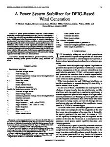
Case 3) Three-phase rectifier This case shows that CEMS does not experience the numerical chatter exhibited in case 2, even when partitioning a switching circuit. The three-phase rectifier circuit shown in Figure 9 was partitioned using the approach described for Figure 2. (For models of this size, the run-times of CEMS and SimPowerSystems are approximately the same.) Figure 5. Current waveform overlay for case 1.
Case 2) Diode and RL circuit This case shows that CEMS is insensitive to numerical chatter. Consider the diode and RL circuit shown in Figure 6
108
results provided by CEMS are consistent with SimPowerSystems. Because the equation formulation and discretization approaches in SimPowerSystems and CEMS are different, some result discrepancies are expected. Among the case studies analyzed, of which some were shown in this paper, the results by CEMS are consistent, and in some cases, better than the results provided by SimPowerSystems fixed-step solver. (A comparison between CEMS and the variable-step solver in SimPowerSystems has not been made.) Since accuracy appears to be acceptable at this stage of the work, UT-CEM plans to move forward to demonstrate the increase in speed.
Figure 9. Partitioned three-phase rectifier circuit (case 3).
VI. [1] [2] [3]
Figure 10. DC side current waveform.
[4] [5] [6] [7] [8] [9]
Figure 11. Close-up of current waveform shown in Figure 10. [10]
As seen from the DC side current in Figure 10 and Figure 11, SimPowerSystems gives incorrect results as it uses trapezoidal integration. Although in SimPowerSystems these oscillations can be suppressed by using a variable-step solver, variable-step solvers are too inefficient in large model simulation to be practical. From Figure 11, the results provided by CEMS do not exhibit oscillations. Additiionally, it was verified that the partitioned and unpartitioned results provided by CEMS agree with one another. V.
[11] [12] [13] [14]
SUMMARY AND CONCLUSIONS
Compatibility and speed are at the core of UT-CEM’s effort to develop a power system solver. Compatibility will allow users to retain existing SimPowerSystems schematics and optionally execute them in CEMS. Speed is sought by partitioning large power system models and using multithreading programming techniques to exploit multicore technology.
[15] [16] [17]
Accuracy is more important than speed. In this regard, considerable resources are currently allocated to ensure that the
109
REFERENCES
The MathWorks, Inc. (2010). SimPowerSystems 5 User's Guide. [Online]. Available: http://www.mathworks.com/help/toolbox/physmod/powersys/ Manitoba HVDC Research Center. (2010, Jan.). [Online]. Available: https://pscad.com/products/pscad/ Y. Zhang, R. Dougal, B. Langland, J. Shi, and J. Tang, "Method for partitioning large system models when using latency insertion method to speed network solution," in Proc. 2009 Grand Challenges in Modeling and Simulation. E. Broughton, B. Langland, E. Solodovnick, and G. Croft. (2003). Virtual Test Bed User's Manual. Columbia, SC: University of South Carolina. Opal-RT Technologies Inc. (2009). eMEGAsim and eDRIVEsim Product Information & Simulation Application Examples. [Online]. Available: http://www.opal-rt.com/sites/default/files/technical_papers/ The MathWorks, Inc. (2010). Simulink 7 User's Guide. [Online]. Available: http://www.mathworks.com/help/toolbox/simulink/ R. A. Rohrer, "Circuit partitioning simplified," IEEE Trans. Circuits and Systems, vol. 35, pp. 2-5, 1988. A. Sangiovanni-Vincentelli, C. Li-Kuan, and L. O. Chua, "A new tearing approach - node tearing nodal analysis," in Proc. 1975 IEEE International Symposium on Circuits and Systems, pp. 143-147. B. M. Zhang, N. A. Xiang, and S. Y. Wang, "Unified piecewise solution of power-system networks combining both branch cutting and node tearing," International Journal of Electrical Power & Energy Systems, vol. 11, pp. 283-288, Oct 1989. P. W. Aitchison and A. Klos, "Network tearing - an alternative method," International Journal of Electrical Power & Energy Systems, vol. 13, pp. 308-320, Dec 1991. C. Yue, X. Zhou, and R. Li, "Node-splitting approach used for network partition and parallel processing in electromagnetic transient smiulation," in Proc. 2004 International Conference on Power System Technology. I. S. Duff, A. M. Erisman, and J. K. Reid. (1986). Direct Methods for Sparse Matrices. Oxford: Oxford University Press. N. R. Watson and G. D. Irwin, "Electromagnetic transient simulation of power systems using root-matching techniques," IEE Proceedings: Generation, Transmission and Distribution, vol. 145, pp. 481-486, 1998. W. Gao, E. Solodovnik, R. Dougal, G. Cokkinides, and A. P. S. Meliopoulos, "Elimination of numerical oscillations in power system dynamic simulation," in Proc. 2003 18th IEEE Applied Power Electronics Conference and Exposition, pp. 790-794. J. R. Marti and J. Lin, "Suppression of numerical oscillations in the EMTP," IEEE Trans. Power Systems, vol. 4, pp. 739-747, 1989. K. Strunz, "Flexible numerical integration for efficient representation of switching in real time electromagnetic transients simulation," IEEE Trans. Power Delivery, vol. 19, pp. 1276-1283, Jul. 2004. C. S. Chang, L. R. Lu, and F. S. Wen, "Power system network partitioning using tabu search," Electric Power Systems Research, vol. 49, pp. 55-61, Feb. 15 1999.
[18] G. Karypis, R. Aggarwal, V. Kumar, and S. Shekhar, "Multilevel hypergraph partitioning: applications in VLSI domain," in Proc. 1997 Design and Automation Conference, pp. 526-529. [19] B. W. Kernighan and S. Lin, "An efficient heuristic procedure for partitioning graphs," Bell Laboratories Record, vol. 49, pp. 291-307, 1970. [20] F. M. Uriarte and K. L. Butler-Purry, "Multicore simulation of an ACradial shipboard power system," in Proc. 2010 Power Engineering Society General Meeting. [21] J. Albahari and B. Albahari. (2007). C# 3.0 in a Nutshell (5th ed.) Cambridge: O’Reilly. [22] J. A. Hollman and J. R. Marti, "Real time network simulation with PCcluster," IEEE Trans. Power Systems, vol. 18, pp. 563-569, 2003. [23] A. Yamane and J. Bélanger. (2010). Comparison between ARTEMIS 5th order Integration method used with the eMEGAsim Simulation Platform and the classical TUSTIN 2nd order method used in PSCAD and SimPowerSystems software. [Online]. Available: http://www.opalrt.com/technical_documents
110