Mar 9, 2009 - very detail the SDFT in Section II. DFT ... SDFT are tested by three examples in Section III. Finally .... AMD K6-200 CPU time of each method.
IEEE TRANSACTIONS ON POWER DELIVERY, VOL. 16, NO. 3, JULY 2001
361
A Precise Calculation of Power System Frequency Jun-Zhe Yang and Chih-Wen Liu, Member, IEEE
Abstract—A precise digital algorithm based on Discrete Fourier Transforms (DFT) to estimate the frequency of a sinusoid with harmonics in real-time is proposed. This algorithm that we called the Smart Discrete Fourier Transforms (SDFT) smartly avoids the errors that arise when frequency deviates from the nominal frequency, and keeps all the advantages of the DFT e.g., immune to harmonics and the recursive computing can be used in SDFT. These make the SDFT more accurate than conventional DFT based techniques. In addition, this method is recursive and very easy to implement, so it is very suitable for use in real-time. We provide the simulation results compared with a conventional DFT method and second-order Prony method to validate the claimed benefits of SDFT. Index Terms—Discrete Fourier Transforms (DFT), frequency estimation, phasor measurement.
deviates from nominal frequency, its speed is even faster than DFT, and it can get exact solution in the presence of harmonics. The organization of this paper is as follows: We describe in very detail the SDFT in Section II. DFT, Prony method and SDFT are tested by three examples in Section III. Finally, we give a conclusion in Section IV. II. THE PROPOSED DIGITAL ALGORITHM This section presents the algorithm of the SDFT that calculates the frequency from a voltage/current signal. Consider a siwith th harmonic nusoidal input signal of frequency given by: (1)
I. INTRODUCTION
where
F
REQUENCY is one of the most important quantities in power system operation because it can reflect the dynamic energy balance between load and generating power. So frequency is always regarded as an index of the operating practices, and utilities can know the system energy balance situations by observing frequency variations. Frequency may vary very fast in the transient events such that it is difficult to track it accurately. In addition, there are many devices, such as power electronic equipments and arc furnaces, etc. generating lots of harmonics and noise in modern power systems. It is therefore essential for utilities to seek and develop a reliable method that can measure frequency in presence of harmonics and noise. With the advent of the microprocessor, more and more microprocessor-based equipments have been extensively used in power systems. Using such equipments is known to provide accurate, fast responding, economic, and flexible solutions to measurement problems [1]. Therefore, all we have to do is to find the best algorithm and implement it. There have been many digital algorithms applied to estimating frequency during recent years, for example Modified Zero Crossing Technique [2], Level Crossing Technique [3], Least Squares Error Technique [4]–[6], Newton method [7], Kalman Filter [8]–[10], Prony Method [11], and Discrete Fourier Transform (DFT) [12], etc. For real-time use, most of the aforementioned methods have trade-off between accuracy and speed [13]. A precise digital algorithm, namely Smart Discrete Fourier Transform (SDFT) is presented and tries to meet the real-time use. SDFT has the advantages that it can obtain exact solution when frequency
: the amplitude, : the phase angle. is sampled with a sampling rate ( Suppose that waveform to produce the sample set
) Hz
(2) is conventionally represented by a phasor (a The signal complex number) (3) Then
can be expressed as (4)
where denotes complex conjugate. Moreover, the fundamental is given by frequency (60 Hz) component of DFT of (5) Combing (4) and (5) and taking frequency deviation ] into consideration, we obtain: [
Manuscript received November 9, 1998; revised September 20, 2000. The authors are with the Department of Electrical Engineering, National Taiwan University, Taipei, Taiwan. Publisher Item Identifier S 0885-8977(01)03089-8. 0885–8977/01$10.00 © 2001 IEEE
Authorized licensed use limited to: National Taiwan University. Downloaded on March 9, 2009 at 04:33 from IEEE Xplore. Restrictions apply.
362
IEEE TRANSACTIONS ON POWER DELIVERY, VOL. 16, NO. 3, JULY 2001
(6) We rearrange (6) as the following (9) where
and
Rearranging (9) further, we obtain
(7)
We use the following identity to simplify (7)
(8)
Then (7) can be expressed as
(10)
Authorized licensed use limited to: National Taiwan University. Downloaded on March 9, 2009 at 04:33 from IEEE Xplore. Restrictions apply.
YANG AND LIU: A PRECISE CALCULATION OF POWER SYSTEM FREQUENCY
If we define
,
,
and
363
as
(22) If we multiply “ then we get
” on both sides of (21) and (22), respectively,
(23) (11) (24) Subtracting (15) from (23) and subtracting (21) from (24), reand obtain spectively, we can erase (12)
(25)
(26) and
Repeat similar operation to erase the tions will become
, then the equa-
(13)
(27) (28) , where Dividing (28) by (27), we get
.
(29) (14) Then (9) can be expressed as
Then expand (29), and use numerical method to find the solution of “ .” And from the definition of “ ” in (16), we can get the exact solution of the frequency
(15) Except the parts of th harmonic, so far the development of the algorithm of SDFT are the same as the conventional DFT method. So the SDFT can keep all advantages of DFT such as recursive computing manner. But in the DFT, it assumes that the frequency deviation is small enough to be ignored, and it , so traditional DFT based methods always considers incur error in estimating frequency and phasor when frequency deviates from nominal frequency (60 Hz). If we want to get and into consideration. exact solution, we must take , So we define
Re
(30)
From (29), it is observed that SDFT can provide exact frequency , , and in the presence of harusing , monics. Moreover, we can estimate phasor after getting exact “ ” by the following equations: (31)
(32) (16) And from (10), we will find the following relations
(33) (17) (18) (19) (20)
Then
It appears that SDFT can take integral order harmonics into consideration. To distinguish easily, SDFT means calculating and we add suffix to the others, for exfrequency for and ample SDFT and SDFT calculate frequency for , respectively. And here we offer the polynomial equa): tion of SDFT (
(21)
Authorized licensed use limited to: National Taiwan University. Downloaded on March 9, 2009 at 04:33 from IEEE Xplore. Restrictions apply.
364
IEEE TRANSACTIONS ON POWER DELIVERY, VOL. 16, NO. 3, JULY 2001
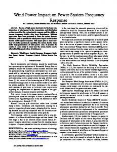
Fig. 1. Comparison of frequency calculations among DFT, Prony, SDFT, and SDFT . [Test signal: x(t) = cos(wt), f = 61 Hz].
(a)
where
Actually, if we assume that from the beginning of development of the algorithm, we will derive a polynomial equation similar to (29) that provide exact frequency in the presence of nonintegral harmonic. We add suffix “ ” to SDFT means that has taken nonintegral harmonics into consideration. Although we can take all of the harmonics into consideration, we still need a digital filter to decay noise and high order harmonics. Since, in SDFT, the more harmonics taken into consideration, the more CPU time needed in computing. The advantages of digital filtering are no voltage drop, no temperature drift, no noise addition, and don’t have any analog filter element features, like aging. Besides these, digital filter can be implemented in microprocessor-based equipment. These make us choose a digital filter to filter noise and high order harmonics. There are many digital filters that we can choose e.g., Hanning, Hamming and Blackman windows. In our simulations we will use the Blackman window for filtering.
(b)
III. SIMULATION RESULTS Simulation results presented in this section were all simulated from Matlab and showed a fair comparison to both the DFT method and Prony method. In Fig. 1, we showed that SDFT could obtain an exact solution identical to the Prony method under frequency deviation in a pure sinusoidal waveform. Fig. 1 also shows the performance of SDFT method and conventional DFT method. It is observed that conventional DFT method gives the wrong frequency calculations. In Fig. 2(a), SDFT and SDFT are observed to obtain the exact solution. While the SDFT and Prony methods test the same signal without filtering, we find that Prony is worse than SDFT in the presence of harmonics, but if the test signal is filtered by a Blackman window (window size = 16) for estimation,
(c) Fig. 2. (a) Comparison of frequency calculations among SDFT, Prony, SDFT , SDFT . [Test signal: x(t) = cos(wt) + 0:05 cos(3wt) + 0:02 cos(5wt), f = 60:5 Hz]. (b) Comparison of frequency calculations among SDFT, Prony, SDFT with Blackman window. (c) Comparison of frequency calculations among SDFT, Prony, SDFT , SDFT with Blackman window. [Test signal: x(t) = cos(wt) + 0:05 cos(3wt) + 0:02 cos(2� 3 380 3 t), f = 60:5 Hz].
we find that the SDFT and Prony methods have similar performance. Since the SDFT can deal with 3rd harmonic and a
Authorized licensed use limited to: National Taiwan University. Downloaded on March 9, 2009 at 04:33 from IEEE Xplore. Restrictions apply.
YANG AND LIU: A PRECISE CALCULATION OF POWER SYSTEM FREQUENCY
365
(a)
(b)
(c)
(d)
Fig. 3. (a) Frequency variation of test signal, x(t) = cos(wt), f = 60 + 0:5 sin(2�t) Hz. (b) Comparison of error of frequency calculations between SDFT and Prony. (c) Comparison of error of frequency calculations between SDFT and SDFT . (d) Comparison of error of frequency calculations between SDFT and SDFT .
nonintegral harmonic, in Fig. 2(c), only the SDFT gets the exact solution. In Fig. 3(a), the frequency is changed as a sine wave and 3rd, 5th harmonics is also added in test signal during 1 second. We can observe the errors of SDFT and Prony with Blackman window in Fig. 3(b), and the errors of SDFT and SDFT without filter in Fig. 3(c). Although SDFT and SDFT can resist the effect of the 3rd, 5th harmonics, the effect of frequency variation makes them get some small errors. In Fig. 3(d), we change 5th harmonic to a nonintegral harmonic, and of course SDFT has better performance than SDFT . However, this is a special case for SDFT . In fact, SDFT spends more time in computing than SDFT , and sometimes it has convergence problem when there are more than two harmonics in the signal. Anyway, from Fig. 3 we can conclude that SDFT-family algorithms (SDFT, SDFT and SDFT ) are better than DFT method and Prony method for frequency calculation. By comparison of computation speed, Table I shows the AMD K6-200 CPU time of each method. There are 960 data
TABLE I COMPUTATION TIME
per second computed by each method [the test signal is the same as in Fig. 3(a)] without a Blackman window to calculate the frequency, while adding a Blackman window will add 0.91 second to the computation. We find that SDFT is the fastest method in these computations, even faster than DFT, because SDFT counts frequencies directly, but DFT has to count the phase first and then use the phase difference to count frequencies. The faster speed of SDFT over the Prony method is because recursion can be used in SDFT. IV. CONCLUSION In this paper we introduce the SDFT-family methods and demonstrate their performance. SDFT both keeps
Authorized licensed use limited to: National Taiwan University. Downloaded on March 9, 2009 at 04:33 from IEEE Xplore. Restrictions apply.
366
IEEE TRANSACTIONS ON POWER DELIVERY, VOL. 16, NO. 3, JULY 2001
the advantages of DFT and also deals with the cause of frequency deviation errors, while taking harmonics into consideration. These aspects make SDFT a fast, accurate and harmonic-resisting method. But we do not suggest taking all the harmonics into consideration, since that would require too much computation time. Alternatively, using a smoothing window to decay the high order harmonics and just taking the low order harmonics into consideration will be more efficient and suitable for power systems under real-time demands. REFERENCES [1] P. J. Moore, R. D. Carranza, and A. T. Johns, “Model system tests on a new numeric method of power system frequency measurement,” IEEE Trans. on Power Delivery, vol. 11, no. 2, pp. 696–701, Apr. 1996. [2] M. M. Begovic, P. M. Djuric, S. Dunlap, and A. G. Phadke, “Frequency tracking in power networks in the presence of harmonics,” IEEE Trans. on Power Delivery, vol. 8, no. 2, pp. 480–486, Apr. 1993. [3] C. T. Nguyen and K. Srinivasan, “A new technique for rapid tracking of frequency deviations based on level crossings,” IEEE Trans. on Power Apparatus and Systems, vol. PAS-103, no. 8, pp. 2230–2236, Aug. 1984. [4] I. Kamwa and R. Grondin, “Fast adaptive schemes for tracking voltage phasor and local frequency in power transmission and distribution systems,” IEEE Trans. on Power Delivery, vol. 7, no. 2, pp. 789–795, Apr. 1992. [5] M. S. Sachdev and M. M. Giray, “A least error squares technique for determining power system frequency,” IEEE Trans. on Power Apparatus and Systems, vol. PAS-104, no. 2, pp. 437–443, Feb. 1985. [6] M. M. Giray and M. S. Sachdev, “Off-nominal frequency measurements in electric power systems,” IEEE Trans. on Power Delivery, vol. 4, no. 3, pp. 1573–1578, July 1989. [7] V. V. Terzija, M. B. Djuric, and B. D. Kovacevic, “Voltage phasor and local system frequency estimation using newton type algorithm,” IEEE Trans. on Power Delivery, vol. 9, no. 3, pp. 1368–1374, July 1994. [8] M. S. Sachdev, H. C. Wood, and N. G. Johnson, “Kalman filtering applied to power system measurements for relaying,” IEEE Trans. on Power Apparatus and System, vol. PAS-104, no. 12, pp. 3565–3573, Dec. 1985.
[9] A. A. Girgis and T. L. D. Hwang, “Optimal estimation of voltage phasors and frequency deviation using linear and nonlinear kalman filter: Theory and limitations,” IEEE Trans. on Power Apparatus and Systems, vol. 103, no. 10, pp. 2943–2949, Oct. 1984. [10] A. A. Girgis and W. L. Peterson, “Adaptive estimation of power system frequency deviation and its rate of change for calculating sudden power system overloads,” IEEE Trans. on Power Delivery, vol. 5, no. 2, pp. 585–594, Apr. 1990. [11] T. Lobos and J. Rezmer, “Real-time determination of power system frequency,” IEEE Trans. on Instrumentation and Measurement, vol. 46, no. 4, pp. 877–881, Aug. 1997. [12] A. G. Phadke, J. S. Thorp, and M. G. Adamiak, “A new measurement technique for tracking voltage phasors, local system frequency, and rate of change of frequency,” IEEE Trans. on Power Apparatus and Systems, vol. 102, no. 5, pp. 1025–1038, May 1983. [13] Ph. Denys, C. Counan, L. Hossenlopp, and C. Holweck, “Measurement of voltage phase for the French future deffence plan against losses of synchronism,” IEEE Trans. on Power Delivery, vol. 7, no. 1, pp. 62–69, Jan. 1992.
Jun-Zhe Yang was born at Tainan, Taiwan, in 1971. He received the B.S. degree in electrical engineering from Tatung Institute of Technology in 1994, and the M.S. and Ph.D. degrees from National Taiwan University in 1997 and 1999. Now, he serves as Second Lieutenant in Air Force. His interested researches include GPS time transfer and the measurement technique in power system.
Chih-Wen Liu (M’94) was born in Taiwan in 1964. He received the B.S. degree in electrical engineering from National Taiwan University in 1987, and the M.S. and Ph.D. degrees in electrical engineering from Cornell University in 1992 and 1994. Since 1994, he has been with National Taiwan University, where he is Associate Professor of electrical engineering. He is a Member of the IEEE and serves as a Reviewer for IEEE TRANSACTIONS ON CIRCUITS AND SYSTEMS. His main research area is in application of computer technology to power system monitoring, operation, protection and control. His other research interests include GPS time transfer and chaotic dynamics and their application to system problems.
Authorized licensed use limited to: National Taiwan University. Downloaded on March 9, 2009 at 04:33 from IEEE Xplore. Restrictions apply.