Sep 15, 2008 - In this paper we describe a profile-driven, paper-based sketching interface which in- ..... shape of the flask on a piece of paper as shown in Fig- ure 5(a). Once the ..... putation, pages 835â844, 2005. [6] P. J. Farrugia, J. C. Borg ...
A Profile-driven Sketching Interface for Pen-and-Paper Sketches Alexandra Bartolo, Philip Farrugia, Kenneth Camilleri and Jonathan Borg Faculty of Engineering University of Malta {abbart, pjfarr, kpcami, jcborg}@eng.um.edu.mt
Abstract
(CAD) tools to redraw the initial conceptual scribbles to obtain an accurate and detailed representation of their design as well as the possibility of obtaining a virtual 3D representation of the concept. Drawing with CAD systems involves using Window, Icon, Menu and Pointer (WIMP) interfaces and so designers spend a considerable amount of time to redraw the conceptual design sketches, using interfaces that are not as natural as the drawing habits of the designer. Sketching interfaces for design solutions make the tools available in CAD systems more accessible by replacing the WIMP interface with interfaces that are closer to the designers’ drawing habits [4]. The drawback of most of the existing sketching interface tools is that these make use of digital ink and hence require the use of Tablet PCs. Despite the fact that Tablets are becoming more popular, designers still tend to prefer physical pen and paper since besides being cheaper, pen and paper is more comfortable and portable than any on-line sketching device [10, 12].
Sketching interface tools are developed to allow designers to benefit from the powerful computational tools available in computer aided design systems. However, despite the number of sketching tools such as PDAs and Tablet PCs available on market, designers typically create a number of initial conceptual ideas using paper-based sketches and scribbles such that these tools remain inaccessible to designers in the early design stages. In this paper we describe a profile-driven, paper-based sketching interface which infers the 3D geometry of objects drawn by designers using the traditional pen and paper sketching. We show that by making full use of the shape information present in the scribbled drawing, it is possible to obtain a paper-based sketching interface that retains the simplicity of the earlystage design drawings while allowing for the modeling of a variety of object shapes.
For this reason, our past research has focused on algorithms that are needed to create a computer interface that infers the 3D shape information of the object directly from the designers’ paper-based sketch. By using our sketching interface, the designer will be required to annotate the paperbased scribble using a specific annotation language. The annotated scribble must then be digitized using scanners or digital cameras. Once digitized, the sketch interpretation algorithms convert the flat annotated drawing into a 3D model without the need of any further human intervention. The advantage of sketching interface proposed in this paper is that unlike our previous interfaces, this is a profile-driven sketching interface, that is, the algorithms involved in the interpretation will make full use of the scribbled profile for interpretation. This allows us to reduce the rules governing our earlier annotation language described in [3] and hence make the sketching interface easier to use. In this paper, we also show that by making the interface tool profile-driven, we can increase the flexibility of the tool by allowing more complex free-form shapes to be modeled.
1. Introduction Paper-based sketches and scribbles are used extensively in the early design stages, when the designer is in the process of externalizing form concepts. Freehand sketches and scribbles are ideal during the early design stages since when scribbling, the designer does not need to adhere to specific drawing rules. This allows the designer to quickly generate a number of scribbles depicting different solutions to a design problem. Thus, by scribbling in the early design stages, the designer is more likely to engage in innovative design [14]. The utility of the scribbles drawn during the early design stages is however somewhat limited in the later design stages. The scribbles lack accuracy and so they cannot be used directly in more advanced design stages when accuracy becomes important. The scribbles also represent the design concept as a flat, static image which are not as effective as 3D virtual models when illustrating design concepts to clients or peers. Thus, designers will often use Computer-Aided Design
VL/HCC Workshop: Sketch Tools for Diagramming Herrsching am Ammersee, Germany 15 September 2008 Editors: Beryl Plimmer & Tracy Hammond
The paper is presented as follows: Section 2 gives a review of existing sketching interfaces, Section 3 describes
1
the sketching language, Section 4 describes the image preprocessing techniques required, Section 5 describes the interpretation algorithm, Section 6 presents the results obtained while Section 7 concludes the paper.
3D primitive symbol
Object Profile
Plane Line
Path Line
2. Background Work Sketching interfaces for 3D modeling may be broadly classified into three categories namely, gestural modeling systems, reconstructional modeling systems and hybrid systems. The differences between these approaches lies mainly in the way the interpretation algorithm generates the 3D model of the object. This in turn determines the type of input drawing the designer is expected to make. Gestural modeling interfaces such as Pencil [5], Teddy [8] and GIDeS++ [11] among others, use symbolic modeling gestures to trigger an action such as a 3D operation or a Boolean operation that will modify an evolving 3D model. Using these interfaces, the 3D model is constructed in an interactive manner, with the designer making use of a set of gestures to guide the modeling. Thus, although these interfaces are more intuitive than the WIMP interfaces, the designer is still required to draw the sketch in a manner that differs from the natural drawing style. The reconstructional modeling interfaces such as those proposed in [9], [7] and [13] among others, involve the determination of the topology and geometry of a 3D object that is represented by 2D views or by single 3D projection. In comparison to gestural modeling interfaces, these systems have two main advantages. The first is that with this approach, the designer is expected to sketch in a specific drawing convention which the designer would already be familiar with, secondly, this approach has the benefit of being automated. However, with the exception of Freehand [7], the existing systems that fall in this category are limited to modeling of polyhedral shapes. Hybrid modeling interfaces combine the gestural modeling approach with the reconstructional modeling approach. In these systems, the designer draws the object using digital ink and then use gestures to modify the 3D model. The advantage of these systems is that the initial drawing is closer to the designers’ drawing style while the gestures ensure that the interpretation remains fairly easy, hence allowing for the modeling of more complex objects. Interfaces that fall in this category may also handle a degree of inaccuracy in the designers’ drawings. This is a feature that is important in the early conceptual design stage, when accuracy tends to be ignored. However, as with gestural modeling, continuous user interaction is required to generate the 3D model. Most of the sketch-based interfaces described in literature require that the designer sketch is made using digital ink as this somewhat simplifies the interpretation problem
VL/HCC Workshop: Sketch Tools for Diagramming Herrsching am Ammersee, Germany 15 September 2008 Editors: Beryl Plimmer & Tracy Hammond
z
z
Cross-sectional Profile
y x (a) Intended 3D object
x (b) Sketch language representation
Figure 1. The annotation tool described in [3]
since the sketch strokes may be captured directly as vectors and the interface will have access to the temporal information of the ink strokes. However, pen and paper are still the designers’ preferred drawing medium [12], such that it is necessary to develop a sketching interface that allows the designer to give instructions to the sketch interpretation algorithms by sketching on paper in an off-line environment. This is necessary to retain the flexibility and portability of the physical paper medium. The sketching interface described in [3] bridges the gap between the user flexibility and ease of computation by creating a paper-based annotation tool, based on the prescribed sketching language described in [6]. Using this annotation tool, the designer annotates the initial scribble using plane lines, path lines, cross-sectional profiles and 3D primitive symbols as shown in Figure 1. Once digitized, the annotated drawing is used as input to the interpretation algorithms which will use the annotations and the scribbled object profile to deduce the geometric operations required by a particular CAD system to generate the 3D model of the object [3]. However, in this sketching interface, the interpretation algorithms do not make full use of the shape information present in the object profile and so, the annotation rules force the designer to think in terms of CAD system commands when annotating the drawing, limiting the flexibility of the sketching interface. Furthermore, by failing to make full use of the object profile, the sketching interface becomes limited to the modeling of simple object shapes. Thus, it is necessary to enhance positive aspects of the sketching interface described in [3] by making fuller use of the shape information present in the object profile. This would enable the interpretation algorithms to infer the 3D structure of the drawing independently from the geometric operations of any CAD system, thus increasing the flexibility of the sketching interface.
2
P L3 P L3
P L2 P L2 P L1 z
z x
P L1 y
z x
x
Figure 3. Drawing profiles
Figure 2. Drawing plane lines
3. A Profile-driven Sketching Interface
resides. The plane lines are therefore used to indicate the planes of interest in the object profile as shown in Figure 2. In general each drawing will be annotated with at least two plane lines, defining the base of the object and the top-most part of the object. Most objects will however require additional plane lines to indicate intermediary planes of interest. These will include all planes where the cross-section of the object changes shape. In order to reduce the ambiguities in the interpretation of the object which may result if the drawings are represented by different topologies, the annotation rules specify that the object must be drawn in an upright manner as shown in Figure 2(a). This ensures that the base plane line will always be that which has the smallest z coordinate, allowing the interpretation algorithms to use this plane line as a point of reference when inferring the 3D geometry of the object.
The new profile-driven sketching interface considers the modeling of free-form object shapes that have a single planar axis, however, the sketching interface can cater for all shapes that fall within this research restriction. The sketching interface acts in an off-line manner, that is, the designer must complete the entire drawing before commencing the interpretation of the drawing. This allows the designer to use the traditional pen and paper medium but at the same time, does not exclude the designer from using a Tablet PC if this is preferred. Designers using this sketching interface are required to follow two drawing steps, namely the scribbling step and the annotation step. In the scribbling step, the designer scribbles the object profile, thus communicating with the interpretation algorithm the intended shape of the object. In the annotation step, the designer annotates the object profile using three annotation components, namely plane lines, cross-sectional profiles and 3D primitive symbols. The use of these annotations is governed by simple annotation rules which shall be described in the following sections. In order to enable the interpretation algorithms to distinguish the object profile from the annotations, different pen colours are used for the object profile and for the annotations. Rather than specifying the use of two particular pen colours, the annotation rules indicate that the pen colours selected should have sufficient contrast such that the interpretation algorithm may successfully distinguish between the two colours.
3.2. The cross-sectional profiles The sketching interface uses cross-sectional profiles to resolve the ambiguities that arise when 3D objects are represented on a flat plane. Furthermore, by using cross-sectional profiles to specify the geometry of the object, designers using this sketching interface will be able to model nonpolyhedral objects that may have any arbitrary shape. The use of cross-sectional profiles in conjunction with the plane lines is inspired from the concept of removed sections as described in the BS8888:2002 drawing standards [6] such that the cross-sectional profiles may be compared to successive removed sections which indicate the object’s crosssectional shape at consecutive cutting planes. Furthermore, as shown in Figure 3, these cross-sectional profiles are drawn parallel to the respective plane lines whose role is similar to the cutting planes described in these drawing standards, this is also typical of the BS8888:2002 drawing standards. Thus, the sketching interface minimizes the initial learning curve required to use the interface by using annotation rules that are natural to the designer. The annotation rules for the cross-sectional profiles also
3.1. The plane lines The use of plane lines is motivated by the concept of workplanes which are commonly used in CAD systems to describe 3D objects. Thus, designers using this sketching interface will already be familiar with the annotation rules that govern the use of the plane lines [6]. Plane lines define the side of a plane on which a cross-sectional profile
VL/HCC Workshop: Sketch Tools for Diagramming Herrsching am Ammersee, Germany 15 September 2008 Editors: Beryl Plimmer & Tracy Hammond
z y
x
3
Cube Cylinder Sphere Cone Pyramid Wedge
Figure 4. The 3D primitive symbols
determine the position at which these profiles must be drawn. Besides being parallel to their respective plane line, the cross-sectional profiles must be positioned such that they are closest to their associated plane line. It is also necessary to ensure that the cross-sectional profiles do not intersect any other annotation or the object profile. Furthermore, the annotation rules specify that the cross-sectional profiles are used to give information about the shape and not the actual size of the object’s cross-section. This rule allows designers to draw the cross-sectional profiles in a convenient size, freeing the designer from the burden of scaling each new cross-sectional profile with respect to the previous cross-sectional profiles. This is possible since the actual size of the object will be determined by the interpretation algorithms from the shape information present in the object profile.
(a) scribble profile
(b) base plane line & cross-sectional profile
(c) 2nd plane line & cross-sectional profile
(c) 3D primitive symbol
3.3. The 3D primitive symbols Although the use of plane lines and cross-sectional profiles allows for the modeling of a variety of object shapes, certain objects, particularly those which contain 3D primitives such as spheres, cannot be described effectively using just plane lines and cross-sectional profiles. For this reason, the proposed sketching language introduces a set of 3D primitive symbols, shown in Figure 4 that the designer may use to annotate the scribble to indicate that the 3D model should include such a primitive. The symbols chosen reflect common ways with which the 3D primitives are actually sketched, hence ensuring that the symbols are easy to remember and use [6]. As in the case of the cross-sectional profiles, these primitive symbols are used to indicate the shape of the object at that instance. The actual size of the primitive will be obtained by the interpretation algorithm from the size information present in the object profile. The sketch interpretation algorithms currently support 3D primitive symbols that are located in the top extremity of the object. Similar to the cross-sectional profile, the 3D primitive symbol should be drawn close to the plane line on which it resides. However, the primitive symbol does not require a dedicated plane line, such that it is possible for the designer to draw a cross-sectional profile and a symbol in the proximity of the same plane line. This would imply that the 3D primitive resides on a plane whose shape is given by the cross-sectional profile.
VL/HCC Workshop: Sketch Tools for Diagramming Herrsching am Ammersee, Germany 15 September 2008 Editors: Beryl Plimmer & Tracy Hammond
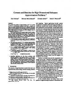
Figure 5. Case Study: ‘Easy grip’ flask
Note that when object shapes are terminated with 3D primitives, the top-most plane line becomes unnecessary since the final shape of the object depends on the particular primitive being used. Thus, when 3D primitive symbols are used, this final plane line may be omitted.
3.4. Case study: ‘Easy grip’ flask In this example we illustrate the use of the profile-driven sketching interface to design a drinking flask with indents that allow for an easier grip of the flask. The base of the flask has a rectangular cross-sectional profile which changes gradually to a circular cross-section at the base of the flask’s neck. The neck of the flask should have a cylindrical shape. Using a black felt-tip pen, the designer scribbles the shape of the flask on a piece of paper as shown in Figure 5(a). Once the object profile is completed, the designer uses a red felt-tip pen to make the necessary annotations. The designer will first annotate the base plane line and the
4
These are necessary to indicate the changes in the shape of the object. In the profile-driven sketching interface, these changes are detected from the object profile such that the designer is only required to indicate the planes where the object’s cross-sectional profile significantly changes its shape. The annotated diagram shown in Figure 6 also contains a larger number of cross-sectional profiles. These are required since the algorithms that generate the 3D model of the object are dependent on CAD system operations such as lofts and extrude operations, forcing the designer to specify the intermediary cross-sectional profile at each plane line. As shown in Figure 6 this may be rather complex when the cross-sectional profile of the object is gradually changing shape. By using the proposed object-driven sketching interface, the designer does not need to specify these intermediary cross-sectional profiles since, as shall be described in the following sections, the number of intermediary planes required to obtain an accurate representation of the object, as well as the cross-sectional shape at these intermediary planes, will be determined automatically from the object profile. As a result, the designer may annotate a drawing using fewer annotations, ensuring that the final drawing is free from unnecessary clutter.
Figure 6. Sketch of the ‘Easy grip’ flask using the annotation language described in [3]
corresponding rectangular cross-sectional profile as shown in Figure 5(b). One may note that, in accordance to the annotation rules, the base plane line lies at the lower part of the paper and that the cross-sectional profile is much smaller than its intended size which is specified by the object profile. Since the shape of the flask changes gradually to a circular cross-section at the flask’s neck, the designer will draw only one other plane line, next to which, the circular cross-section is drawn as shown in Figure 5(c). Next to this plane line, the designer will also draw the cylinder symbol as shown in Figure 5, indicating that the next part of the object should have a cylindrical shape as shown in Figure 5. This case study shows that non-symmetric, free-form objects can be prepared for interpretation with very few annotations. This is possible since the interpretation algorithms used in this sketching interface make full use of the object profile such that annotations are only required to provide information that is either missing or ambiguous in the object profile.
4. Pre-processing of Annotated Drawing Prior to interpretation, the annotated scribble must be preprocessed in order to distinguish between the annotation strokes and the scribble strokes. The annotation strokes must then be further classified as plane lines, cross-sectional profiles and symbols. This is required to allow the interpretation algorithm to use the semantics associated with the different strokes to generate the desired 3D model.
4.1. Colour Segmentation It is first necessary to separate the scribble strokes from the annotations. Since the designer is asked to use contrasting colours to draw the annotations and the scribble strokes, the separation is achieved by clustering the colours in the image into three groups. The largest of these groups will represent the colour of the image background and can therefore be ignored. The remaining two clusters reflect the colours of the annotations and the scribble strokes. Since the designer is not restricted to use two particular colours, it is necessary for the interpretation algorithm to identify which of the two colours are used for the scribble strokes and which are used for the annotations. In our implementation, we distinguish between the annotations and the scribbled strokes from the different stroke characteristics of the annotations and the scribble. The annotated strokes will definitely contain plane lines, which are single straight lines and cross-sectional profiles, which consist of single lines
3.5. Advantages of a profile-driven annotation language Figure 6 shows the representation of the flask described in Section 3.4 using the sketching interface described in [3]. Comparison of this sketch with that drawn using the proposed profile-driven sketching interface shown in Figure 5(d) emphasizes the advantages of the new annotation rules and hence the advantages of a profile-driven sketching interface. Figure 6 contains a larger number of plane lines.
VL/HCC Workshop: Sketch Tools for Diagramming Herrsching am Ammersee, Germany 15 September 2008 Editors: Beryl Plimmer & Tracy Hammond
5
forming closed loops. This contrasts with the strokes forming the scribbled profile which will contain a number of short intersecting segments. This difference in the stroke characteristics is used to identify which of the two colours was used by the designer to draw the scribbled profile and which was used to draw the annotations, hence distinguishing between the annotations and the scribble. One should note that this simplistic distinction between the image colours assumes that the annotated drawing is drawn on a plain sheet of paper that does not contain any textured or patterned background. It also assumes that the drawing is digitized by means of a scanner. This allows us to assume that the background of the digitized image consists of a homogenous colour which will naturally be the largest colour cluster. If however, the image is drawn on textured or patterned paper, or if the image is digitized by means of digital cameras, then the assumption that the image background consists of a single homogenous cluster is not valid. If this is the case, the separation of the scribble from the annotations will require a pre-processing binarisation step. This will identify the image background from the user drawn strokes such allowing the use of the colour segmentation described in the previous paragraph to be applied successfully to the drawing. Since this binarisation is being applied to images which are expected to have difficult backgrounds, we do not rely on a global thresholding algorithm as this is not likely to give a good performance, instead we make use of a local, adaptive binarisation algorithm as described in [2].
line forming a closed loop. In this way, the symbol recognition algorithm is required only when the designer makes use of 3D primitive symbols, in which case the recognition algorithm must distinguish between the different symbols. This approach is less computationally extensive since the recognition algorithm is evoked only when the designer uses the primitive symbols.
5. Preparation to extract the 3D structure Prior to obtaining the 3D shape information from the drawing, it is necessary to re-group the information into components which are representative of the different parts of the 3D object. Each component should consist of two plane lines which define the initial and final positions of the component on the 3D shape, two cross-sectional profiles which define the cross-sectional shape of the object at the initial and final plane lines and two object profile segments that define the shape of the 3D object at the intermediary planes between the initial and final plane lines. A hierarchical representation of these components will enable the interpretation algorithm to determine the 3D shape of the intended design object.
5.1. Association of plane lines and crosssectional profiles Since the annotation rules require that the cross-sectional profiles and 3D primitive symbols are drawn close to the plane lines on which they reside, the minimum distance between the plane lines and the 3D primitive is used to associate the cross-sectional profiles and 3D primitives with the plane lines.
4.2. Scribble simplification Since the designer may draw the object profile as a scribble containing a number of overlapping short segments, it is necessary to group these scribbled strokes into a single contour that represents the designer’s intended shape. This is achieved by treating the over lapping scribble strokes as visual patterns and Gabor filtering techniques are used to group the strokes into an object profile that consists of a single contour [1].
5.2. Segmentation of the object profile The object profile should be divided into components according to the position defined by the plane lines. To achieve this, the plane lines are extrapolated until both ends of the plane line intersect with the object profile as shown in Figure 7(a). The object profile is therefore segmented at these points of intersections as shown in Figure 7(b). The endpoint of each profile segment is used as a pointer to the plane line with which it intersects, such that each profile segment will be associated with an initial and a final plane line. This will automatically associate each profile segment with the cross-sectional profile that define the initial and final cross-sectional shape of the 3D object.
4.3. Classification of annotations The annotations must be further classified as plane lines, profiles and symbols. Although this may be carried out using a symbol recognition algorithm, we do not use the symbol recognition to identify the plane lines and crosssectional profiles. The reason for this, is that these annotations are considerably different from each other and from the 3D primitive symbols and thus may be identified without the use of symbol recognition algorithms. Thus, an annotation is labeled as a plane line if it consists of a single line and as a cross-sectional profile if it consists of a single
VL/HCC Workshop: Sketch Tools for Diagramming Herrsching am Ammersee, Germany 15 September 2008 Editors: Beryl Plimmer & Tracy Hammond
6. Extracting Shape Information The next step of the interpretation algorithm is to extract the 3D geometry from the hierarchical structure of compo-
6
2 P L3
P L3 θ
P L2 P L2
P L2
(b) Rotated Profile (a) Annotated Scribble z
P L1 (a)
width
1 P L1 (b)
y
breadth (c) width vs breadth representation
Figure 7. Segmentation of object profile
z y
x
x
(d) Profiles mapped into 3D space
Figure 8. Mapping the profiles into 3D space nents. Thus, it is necessary to determine the position in the 3D space of the defined cross-sectional profiles and 3D primitives from which the position and shape of the object cross-sections at intermediary planes may be obtained.
sary as it allows us to map the 2D profile into 3D space. In generating the 3D shape information, it is assumed that the origin of the origin of the 3D coordinate system lies on the centre of the bottom-most plane line and therefore, on the outer contour of the bottom plane of the object. Using this co-ordinate system, the breadth of the cross-sectional profile is mapped directly to the y-axis, while the width of the cross-sectional profile is mapped onto the x-axis and z-axis using x = w(sin θ + cos θ) and z = w(cos θ − sin θ) where θ is the angle the plane line makes with the 2D horizontal axis. This mapping is sufficient for the base cross-sectional profile but for subsequent profiles the horizontal and vertical displacement of the centre of the plane line from the base plane line must be added to the x-axis and z-axis respectively.
6.1. Determining the position and scale of the cross-sectional profiles The cross-sectional profiles drawn by the designer give the basic skeleton of the 3D model. These must be scaled to their actual size since the designer is not required to sketch the cross-sectional profile to scale. The proper size of the profiles may be obtained from the length l of the associated plane line since this would have been already extrapolated to the width of the scribbled profile. This length should correspond to the width w of the cross-sectional profile, thus the ratio wl determines the scaling ratio required to give the cross-sectional profile its proper size. Since the crosssectional profiles may have irregular shapes, the width of the cross-sectional profile is determined from the width of the minimum bounding box enclosing the profile. Since the designer is asked to draw the cross-sectional profiles adjacent to the plane lines, it is also necessary to place the cross-sectional profile to its proper position in the object’s 3D topology. This requires that the profile is translated such that the centre of the minimum bounding box coincides with the midpoint of the associated plane line. Note that it is necessary to use the minimum bounding box of the crosssectional profile rather than the centre of gravity of the profile since due to shape irregularities this will not necessarily correspond to the centre of the plane line and hence the centre of scribbled profile. Once the cross-sectional profile has been properly scaled and its proper position determined, it must be rotated to obtain a representation of the profile on a width vs breadth axis as shown in Figure 8. This is neces-
VL/HCC Workshop: Sketch Tools for Diagramming Herrsching am Ammersee, Germany 15 September 2008 Editors: Beryl Plimmer & Tracy Hammond
6.2. Determining the shape of intermediary cross-sectional profiles Since the designer will only specify the planes where significant changes occur in the cross-sectional profile of the object, the cross-sectional profiles defined as annotations will only give a coarse representation of the designer’s intended 3D shape. The scribbled profile will however give information on the more subtle shape information such that it is necessary to define intermediate plane lines which allows the interpretation algorithm to create a 3D model that more accurately defines the designer’s intent. Thus it is necessary to determine intermediate cross-sectional profiles and this is obtained by morphing the cross-sectional profile at a particular plane into the shape specified in the succes-
7
sentation, however, in order to ensure that a 3D model may be generated without user intervention, the interpretation algorithm may, in the absence of any pre-defined user values, modify the values of m and n adaptively for each part in the annotated drawing. To determine the value of n, we apply the polygonization algorithm described in [15] to the two cross-sectional profiles, hence representing the two cross-sectional profiles will be represented by straight line segments. This will give an indication on the distance between salient points on the cross-sectional profiles and so, we use the length of the smallest line segment of the two profiles as an indication of a suitable sampling interval, hence determining the number of samples n required to obtain a smooth representation of the cross-sectional profiles. The value of m is determined in a similar manner, but the polygonization algorithm is applied to the scribbled object profile segments instead of the cross-sectional profiles.
Figure 9. Determining the shape of intermediary cross-sectional profiles
sive plane. The width vs breadth representation of the crosssectional profiles are used to determine the cross-sectional shape of the intermediary planes. The contour paths of each cross-sectional profile are sampled such that each crosssectional profile has the same number of sample points n. This allows us to match the points from the first crosssectional profile to the second cross-sectional profile by straight line segments as shown in Figure 9. These line segments are divided into m equal subdivisions such that the shape of intermediary cross-sectional profiles may be defined by the coordinates of the points on the same subdivision mi . These intermediary cross-sectional shapes must be placed in the context of the scribbled profile and must therefore be positioned and scaled according to the shape information present in the scribble. To achieve this m intermediary plane lines, corresponding to the number of intermediary cross-sectional profiles generated by the morphing algorithm, must be created. Thus, the two scribbled edges are sampled and points of correspondence between the two scribbled edges are determined. These points form the endpoints of the intermediary plane lines. The size and orientation of these plane lines are used to determine the scale and orientation of the intermediary cross-sectional profiles. In this way, it would be possible to create 3D representations of concave and convex objects as well as of objects which are not symmetric about the vertical axis. One should note that in order to evaluate the transition between cross-sectional profiles, we require two user defined parameters, namely the number of sample points taken on the cross-sectional profiles n and the number of intermediary profiles generated m. These two values reflect the accuracy of the representation, with the larger values of m and n giving a smoother object representation. This will however incur an increase in the computational time required to generate the model. The designer may set these values according to the level of accuracy required in the 3D repre-
VL/HCC Workshop: Sketch Tools for Diagramming Herrsching am Ammersee, Germany 15 September 2008 Editors: Beryl Plimmer & Tracy Hammond
6.3. Determining the size and position of 3D primitives If the annotated drawing has 3D primitive symbols, the interpretation algorithm requires a final step before finalizing the 3D model. The primitive symbols gives information about the type of the primitive but the size and position of the primitive in the 3D model are obtained from the scribble. This information can be obtained from the height and width of the scribble segment above the plane line on which the primitive resides. Thus, the bounding box of the scribble area above the plane line is determined and the width and height of the bounding box are evaluated. The height of the bounding box determines the height of the primitive, perpendicular to the base of the primitive. On the other hand, the width of the bounding box, determines the width of the base of the primitive. In the cylinder and cone primitives, this is effectively the diameter of the base circle. The sphere primitive however differs from all other primitives and requires separate processing. The reason for this is mainly due to the fact that it is possible for the object to have parts of the sphere surface as a 3D primitive as shown in the example given in Figure 1. In such cases, the height of the scribble above the plane line does not necessary correspond to the radius of the sphere. Therefore it is necessary to determine the radius and the centre of the sphere. This is done by taking two chords on the scribbled surface above the plane line. The perpendicular bisectors to these chords is constructed and the point of intersection is evaluated. The centre of the sphere may be approximated from the point of intersection of the perpendicular bisectors, while the radius is determined from the distance of this point to the scribbled surface.
8
asked the designers to compare the stroke discrimination using colours with other methods such as different mouse buttons or different pen pressures. From this preliminary survey we noted that designers had a general positive reaction towards this annotation tool, achieving a mean rank of 2.2 with a standard deviation of 1.4 out of a scale of 7 in which a rank of 1 gives a definite positive response and a rank of 7 gives a definite negative response. It is worth noting that 50% of the designers participating in this survey said that they would definitely adopt the sketching language in their design work. When comparing the discrimination between strokes, designers showed preference to the use of different colours in both cases. Ten designers preferred the use of colour to pen pressure whereas nine designers preferred the use of colour to different mouse buttons. The most common reason for this selection is the fact that different colours allow for greater visualization such that it will be easier for the designer’s themselves to distinguish between scribble strokes and annotations. Mouse buttons obtained better results than pen pressure because designers felt that it would be more difficult to control pen pressure. In future, we intend to further evaluate this sketching interface by asking practicing designers to participate in a hands-on experience as this will give us a greater insight on the qualities of the interface. Although this allows the designer to obtain 3D models of a variety of objects, the interface requires further improvements which would make the sketching tool more versatile. One such improvement is to provide the support for the representation of objects that contain more complex features such as form features. The sketching tool described in [6] provides similar support by using the cross-sectional profiles in conjunction with a set of form feature symbols to instruct the interpretation algorithms on the position and shape of these form features. We believe that this feature may be easily adapted in the proposed profile-driven sketching interface particularly since this interface requires much less annotation rules than the sketching language described in [6]. A second improvement would be to allow the sketching interface to model objects that do not consist of a single axis. This may potentially be carried out by allowing the designer to create annotated drawings for different views or parts of the object for which incomplete 3D representations may be created. These incomplete 3D parts may then be merged to form a single 3D object as desired by the designer.
Figure 10. Wire-frame models obtained using the profile-driven sketching interface
7. Results and Discussion Figure 10 shows two wire-frame representations of two objects whose 3D model was obtained using the profiledriven sketching interface described in this paper. One may note that in both cases, the annotated drawing contains few annotations. The sketching interface allows the designer to annotate the drawing using relatively few annotations, freeing the drawing from unnecessary clutter. The two examples shown in Figure 10 demonstrate that the 3D representation is faithful to the shape defined by the designer in the scribbled object. Thus the morphing techniques used to determine the shape of the cross-sectional profile at intermediary planes as well as the adjustment of these intermediary profiles according to the shape of the object profile, allow the interpretation algorithms to deduce the 3D shape of a variety of single axis, free-form objects that have symmetric or asymmetric shapes. In order to determine the strength of this interface tool, a preliminary evaluation was carried out with twelve practicing designers who had a mean of 6.3 years experience in the design field. We gave these designers an annotated sketch and a description of the interface by mail and then asked these designers to assess the usefulness of the proposed annotation tool. Furthermore, since the sketching interface being proposed requires the use of two different colours, we
VL/HCC Workshop: Sketch Tools for Diagramming Herrsching am Ammersee, Germany 15 September 2008 Editors: Beryl Plimmer & Tracy Hammond
8. Conclusion In this paper, we have described a profile-driven paperbased sketching interface that allows the automatic creation of 3D models from an annotated 2D scribble of the object.
9
This sketch-based interface allows designers to retain the traditional pen-and-paper sketching media which are preferred in the earlier design stages. In contrast to existing paper-based sketching interfaces, the interface described in this paper makes full use of the shape information present in the object profile. We have shown that this allows us to simplify the annotation rules such that the designer is expected to annotate the drawing at the most salient planes only and these, together with the object profile, will be sufficient for the interpretation algorithms to infer the 3D geometry of the object, obtaining a faithful representation of the designer’s intent. In fact, annotations are only required to add information that is either missing or ambiguous in the 2D representation of the object profile. This makes the sketching interface more natural to use since the annotations do not rely on the geometry operations of a particular CAD system. In addition, the ability to infer the 3D geometry without the use if a CAD system increases the portability and flexibility of the paper-based sketching interface, making it much easier to integrate the paper-based sketching interface with other interfaces such as 3D editing interfaces. Furthermore, we show that by reducing the number of annotations, the resulting annotated drawings can be much simpler than those created using existing paper-based sketching interfaces. Thus, using a profile-driven sketching interface, the modeling of complex asymmetric shapes does not require a significant increase in the number of annotations needed by the interpretation algorithms to infer the 3D geometry of the object. The preliminary evaluation of the tool suggests that the flexibility of the profile-driven sketching interface is already being appreciated by practicing designers. This is encouraging as it shows that the profile-driven sketching interface helps to bridge the gap that exists between traditional penand-paper sketching and computer-aided design. It also motivates future work in this direction, with the aspiration that the profile-driven sketching interface may be further developed such that designers will have the possibility to generate virtual 3D models of any free-from object.
[2] A. Bartolo, K. P. Camilleri, P. J. Farrugia, and J. C. Borg. Adaptation of Brensens Thresholding Algorithm for Sketched Line Drawings. In Proceedings of the Eurographics Workshop on Sketch-Based Interfaces and Modeling, 2004. [3] A. Bartolo, K. P. Camilleri, P. J. Farrugia, and J. C. Borg. A New Sketch Based Interface using the Gray-level Cooccurrence Matrix for Perceptual Simplification of Paper Based Scribbles. In Proceedings of the Eurographics Workshop on Sketch-Based Interfaces and Modeling, pages 91 – 98, 2006. [4] A. Caetano, N. Goulart, M. Fonseca, and J. Jorge. JavaSketchIt: Issues in Sketching the Look of User Interfaces. In AAAI Spring Symposium on Sketch Understanding, pages 9 – 14, 2002. [5] Z. Ding, Z. S, W. Peng, X. Ye, and H. Hu. PENCIL: A Framework for Expressing Free-Hand Sketching in 3D. In 1st International Conference in Advances in Natural Computation, pages 835–844, 2005. [6] P. J. Farrugia, J. C. Borg, X. T. Yan, K. P. Camilleri, and G. Graham. A Sketching Alphabet for Paper-based Collaborative Design. Journal of Design Research, special issue on Fostering innovation during Early Informal Design Phases, 6:260 288, 2007. [7] T. Honda, S. Kaneko, and Y. Takeda. 3-D Shape Reconstruction for Recognition of Freehand Machine Drawings. Annals of the International Institution for Production Engineering Research, 1993. [8] T. Igarashi, S. Matsuoka, and H. Tanaka. Teddy: A Sketching Interface for 3D Freeform Design. In 26th annual conference on Computer graphics and interactive techniques, pages 409–416, 1999. [9] H. Lipson and M. Shpitalni. Correlation-based Reconstruction of a 3D Object from a single freehand sketch. In AAAI Spring Symposium on Sketch Understanding, pages 99–104, 2002. [10] M. Notowidigdo and R. C. Miller. Off-Line Sketch Interpretation. In AAAI Fall Symposium on Sketch Understanding, pages 120–126, 2004. [11] J. P. Pereira, J. A. Jorge, V. A. Branco, N. F. Silva, T. D. Cardoso, and F. N. Ferreira. Cascading Recognizers for Ambiguous Calligraphic Interaction. In Workshop on SketchBased Interfaces and Modeling, pages 63–72, 2004. [12] P. Rajan and T. Hammond. From Paper to Machine: Extracting Strokes from Images for use in Sketch Recognition. In Proceedings of the Eurographics Workshop on Sketch-Based Interfaces and Modeling, pages 41 – 48, 2008. [13] E. Schweikardt and M. D. Gross. Digital Clay: Deriving Digital Models from Freehand Sketches. In Association for Computer-Aided Design in Architecture, pages 202–211, 1998. [14] M. Shpitalni and H. Lipson. Classification of Sketch Strokes and Corner Detection using Conic Sections and Adaptive Clustering. Journal of Mechanical Design, 119:131–135, 1997. [15] J. Sklansky and V. Gonzalez. Fast Polygonal Approximation of Digitized Curves. Pattern Recognition, 12:327–331, 1980.
Acknowledgments This research is funded by the University of Malta under the research grant R30 31330 and is part of the project Innovative ‘Early Design’ Product Prototyping (InPro)
References [1] A. Bartolo, K. P. Camilleri, S. G. Fabri, and J. C. Borg. Scribbles to Vectors: Preparation of Scribble Drawings for CAD Interpretation. In Proceedings of the Eurographics Workshop on Sketch-Based Interfaces and Modeling, 2007.
VL/HCC Workshop: Sketch Tools for Diagramming Herrsching am Ammersee, Germany 15 September 2008 Editors: Beryl Plimmer & Tracy Hammond
10