2009 15th IEEE Symposium on Asynchronous Circuits and Systems
A Programmable Adaptive Router for a GALS Parallel System Jian Wu, Steve Furber and Jim Garside School of Computer Science, The University of Manchester Oxford Road, Manchester M13 9PL, UK Email:
[email protected],
[email protected],
[email protected]
Abstract
Many large-scale neural simulators have been well developed, such as GENESIS [1] and NEURON [2]. They normally run on workstations or computer clusters which deliver enough computing power but inefficient interconnect. As a result, it is possible to simulate a large scale neural network on these machines but it is hard to run the simulation in real time (which typically means around 1ms per step). The ‘cleverness’ of a brain is believed to be a feature of its connectivity; it is therefore necessary to provide some form of communications network so that neurons modelled on one processor can transmit impulses to other neurons. To this end our system architecture has been designed to facilitate global communication of appropriate data elements. This paper focuses principally on the communication infrastructure in this application-specific multicore system and presents the design of the routers which are the key components. The design challenge is predominantly in the programmability and configurable adaptive routing mechanisms of the router. The router is designed specifically to fulfill the requirement of neural communications and, unlike most on-chip one-to-one interconnect, supports multicast packets. Power consumption is of great concern in the design of very large-scale computation networks. Even a slight waste of power on an individual sub-module can cause a large increase in the power of the whole system and limit the network’s scalability. Because the router is designed specifically for neural simulation, it is intended for the transmission of pulses, not streams. A normal pipelined router doesn’t adjust its activity according to traffic loads. It is very power inefficient in the transmission of pulses because it wastes a lot of power on ‘empty’ packets. Therefore the low power issue is also addressed in this paper, particularly because a powerhungry element, Content Addressable Memory (CAM), is used for the multicast unit. The router is implemented as a synchronous pipelined module in a Globally Asynchronous, Locally Synchronous (GALS) Network-on-Chip (NoC) [3]. Compared to an asynchronous router, it is easier to design using a standard VLSI design flow, and it is easier to incorporate clocked memory blocks such as CAMs and RAMs. The router’s synchronous pipeline is designed to be elastic so that it provides flexibility in flow control and can make effective use of the delay-insensitive feature of the GALS NoC.
This paper describes a router which is the key component of a scalable asynchronous on-chip and inter-chip communication infrastructure for an application-specific parallel computing system. We use this system as a universal platform for real time simulations of large-scale neural networks. The communications router supports multiple routing algorithms, and is pipelined to boost its throughput. The design considerations emphasize programmability and adaptive routing. Programmability offers a highly configurable architecture suited to a range of different applications. Adaptive routing offers a fault-tolerance capability that is highly desirable for large-scale digital computational systems. In addition, many neural applications are inherently fault-tolerant. Therefore, the router may selectively drop some packets in order to maintain a reasonable Quality of Service (QoS). The design objectives are achieved through the use of a synchronous elastic pipeline controlled by a handshake protocol which gives the flexibility to stall the traffic flow during run-time for configuration and other purposes, or to redirect the traffic flow to an alternative link to reroute around a failed or congested link.
1. Introduction The continuing shrinkage of feature size has increased the computing power available on a single chip to almost embarrassing levels. Indeed integration levels appear to have surpassed those exploitable by single, conventional processors, and multicore CPUs are becoming the norm. Although these introduce their own problems – at least to conventional programming models – this abundance of computing power has opened up numerous new opportunities. One computing system which exploits massive parallelism, with limited elemental process speed, is the brain. Here a huge number of slow, simple elements evaluate in parallel and exhibit some remarkable characteristics. The machine described in this paper is designed with the primary application of emulating a large neural system using more ‘conventional’ computing elements. These include a large number of processors, each independently modelling a number of neurons in real time. 1522-8681/09 $25.00 © 2009 IEEE DOI 10.1109/ASYNC.2009.17
23
Authorized licensed use limited to: The University of Manchester. Downloaded on June 2, 2009 at 08:58 from IEEE Xplore. Restrictions apply.
The paper is organized as follows. Section 2 outlines the specific requirements and section 3 briefly overviews how these are mapped onto the system architecture. The router’s functionality is introduced in section 4: section 4A considers the realization of the functionality by presenting an elastic pipeline with a synchronous handshake protocol; routing algorithms are introduced in section 4B. Details of the adaptive ‘emergency routing’ are presented in section 5. Finally, in sections 6 and section 7, conclusions are drawn by providing the results of tests on the synthesized design which show its performance.
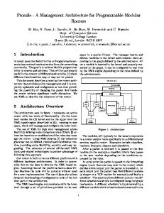
Figure 1. A small array of nodes.
2. Neural Simulation The whole system is biologically inspired and is designed to emulate the operation of a brain. There are particular desired properties and these have influenced the overall architecture. The initial system will have the capacity to model only a small brain, but it is hoped that a larger system may be developed later. The architecture must therefore be scalable. It is intended to run neural models on conventional embedded processors; neurons need considerable (and flexible) interconnection with the ability to multicast events to numerous other neurons which may be modelled on the same processor core, on another core on the same chip, distributed across the machine, or any combination of these [4]. A biological neuron firing is a pure asynchronous event which carries no information other than that it has happened. The occurrence, timing and frequency of firing appears to convey the desired information. Thus the communications packets can be short, typically carrying nothing but the identity of their source and their time of arrival to their destination. Practically, this means that some ‘address’ information may be needed and the data payload is minimal. Timing may be modelled using real time. Neuron firing frequencies are low compared to electronic communication speeds, so the communication latency can be quite long. More importantly some variation in latency is acceptable providing that it is small compared with the neural time constants (which are of the order of milliseconds), which means that some elasticity in the interconnection can be accommodated. The application also influences the expected loading of any communications fabric. It is not expected that it will operate continuously at near to peak loading, but the loading may be quite variable over short timescales. Therefore some elasticity – the ability to buffer a number of events – over short periods is considered desirable. Finally, brains are tolerant of errors: neurons die regularly yet brains (largely) continue to function. It is therefore considered inessential that every event is communicated to all of its targets. A best-effort approach may involve discarding a proportion of signals to allow the majority to arrive relatively unimpeded. There is also the possibility
HOST SYSTEM
Figure 2. System network topology.
– a near certainty as the simulator expands – that some nodes may fail either temporarily due to overloading or permanently due to hardware faults. It is intended that the system should try to tolerate faults at this level too. As well as running its neural applications the system is, in one sense, a ‘conventional’ computer and will need some ‘housekeeping’ features. These include the ability to load and alter the models, which means programming the processor cores and the interconnect. There is also a requirement for debugging which may be used both to commission the system and as a run-time feature to enhance fault tolerance further. These last features have also been designed into this architecture although, perhaps fortunately, they are absent in the brain!
3. System Architecture The system is a massively-parallel computing platform based on Chip MultiProcessor (CMP) technology [5] and 24
Authorized licensed use limited to: The University of Manchester. Downloaded on June 2, 2009 at 08:58 from IEEE Xplore. Restrictions apply.
8bits
200MHz
Header
Link
Input Comms NoC
200MHz
CPU1
CPU2
Outputs
CPU4..
packets. The Communication NoC carries short packets, each comprising an 8-bit header followed by a 32-bit content field that is typically, but not exclusively, used for address information. The neural pulse frequency is represented by the frequency of issuing the packets. There is also an optional 32-bit data payload although this is not present in the majority of the traffic (figure 4). Packets are passed around the NoC asynchronously and serially as 4-bit ‘flits’, but these are assembled into parallel words when passing through the router to improve throughput and make handling easier. There are three types of packet defined:
CPU20
System NoC
133MHz
(Data payload)
Figure 4. Packet definition.
Output Comms NoC
CPU3
Routing key
32bits
Link
Multicast Router
Inputs
32bits
SDRAM interface
SDRAM
•
Figure 3. SpiNNaker Chip Organization.
a self-timed Network on Chip (NoC) infrastructure [6] [7] [8]. It contains an array of computation nodes arranged in a 2D triangular mesh (figure 1), wrapped into a torus (figure 2). Each computation node comprises a large (offchip) memory and a processing chip (figure 3) with 20 ARM968 processor cores running in parallel. A GALS [9] approach is employed to connect the processor cores and other devices. The interconnect fabric is based on a packetswitching NoC which uses the CHAIN delay-insensitive protocol [10] for data transfer. The asynchronous fabric can link elements running at arbitrary speeds and provides both intra- and inter-chip communication. This makes it easy to scale the system from small arrays to many thousands of nodes. In a neural simulation application it is intended that one core on each chip will be designated ‘Housekeeping Processor’ and will handle all the ‘housekeeping’ functions. The other 19 ‘Fascicle Processors’ will run similar neural simulations, effectively applying the same code to their independent data sets. In addition to its processing cores each processing chip has two GALS NoCs. The ‘System NoC’ allows the cores to share resources such as the off-chip SDRAM and is not of particular interest here. The ‘Communication NoC’ passes neural event messages and it is this which links the system together. Each chip contains a router which connects the chip to its neighbours and all of the cores to this fabric, handling neural events and programming and diagnostic information. One of the router design challenges is to control the information flow through the router pipeline to guarantee that the router can be configured at run-time without losing
•
•
A multicast packet is used to carry a neural event message signalling that a neuron has generated a spike. The packet contains only the identifier of the spike’s source – the spiking neuron’s address. Accordingly, multicast routing is based on ‘source-address’ routing in which the packet is steered according to its own ‘wiring’ table in each router. A point-to-point packet is used to carry system information between the ‘Housekeeping’ Processor cores. It is routed to a single destination which is specified in the packet. Steering could be determined algorithmically as the current and final positions are known; however, a look-up table is used which allows different system topologies to be explored. Nearest-neighbour (NN) packets are used for ‘floodfill’ system loading and also for neighbouring nodes to access the local System NoC resources for debugging and fault recovery. Here a nearest-neighbour ‘poke’ write packet has a 32-bit payload and a 32-bit address. It is used to write the payload to the System NoC according to the address. A nearest-neighbour ‘peek’ read packet has a 32-bit address without a payload. It is used to read from the System NoC and returns the result to the neighbour that issued the original packet. This ‘direct’ access to a neighbouring chip’s principal resources can be used to investigate a non-functional chip, to re-assign the ‘Housekeeping’ Processor from outside, and generally to get good visibility into the chip for test and debug purposes.
Each Fascicle Processor can model up to 1,000 neurons. Using the peak spiking rate of each neuron of 1 kHz to estimate the on-chip traffic load gives: 19 × 1000 × 72bit × 1000Hz = 1.368Gbit/s 25
Authorized licensed use limited to: The University of Manchester. Downloaded on June 2, 2009 at 08:58 from IEEE Xplore. Restrictions apply.
(1)
System NoC
AHB Master i/f
AHB Slave i/f
Multicast Router
AHB Slave i/f Buffer
NoC
Packet
Point−to−Point Router
ARBITER
Ready
Packet Checking
Comms
Buffer
Valid
Emergency
Comms
Routing
NoC
Controller
Nearest Neighbour Router
Pipeline Control
Figure 5. Router organization.
This represents the maximum data rate sourced by the chip. In addition there are 6 inter-chip links each with around 1Gbit/s bandwidth, so the overall peak traffic load for the Communication NoC is: 1Gbit/s × 6 + 1.368Gbit/s = ∼ 7.4Gbit/s
The router is divided into several stages by function, each of which is pipelined (figure 5). The first stage identifies packet errors to ensure the correctness of the data flow on the Communication NoC. Occasional errors may be expected due to, for example, corruption on inter-chip links. Incoming packets are de-serialized, arbitrated into a single stream, and synchronized to the router’s clock at the front of this stage. They are buffered so that the main, synchronous part of the router can (typically) accept a packet on every clock cycle.
(2)
The spike rate of a biological neuron varies from a few Hz to a peak rate below 1 kHz. The variability of the spike rate leads to a non-uniform traffic pattern in the Communication NoC. Therefore we need to ensure that the router is able to handle high-frequency packet bursts which may happen from time-to-time. In the meantime, we must pay attention to the design trade-off between performance and power because a high bandwidth is usually achieved by means of a wide bus and/or a high clock frequency, which can imply high power consumption. The next section introduces the architecture of the router.
The only other function performed at this stage is a crude time-out procedure. It is conceivable that errors or corruption could cause packets to propagate erroneously. A rough elapsed time system therefore detects and destroys any incoming packet which is too old to be useful any longer. The time stamp is 2 bits, cycling 00 → 01 → 11→ 10. When the packet is two time phases old it is dropped and an error flagged to the local ‘Housekeeping’ Processor. The length of a time phase can be adapted dynamically to the state of the system; normally, timed-out packets should be very rare so the time phase can be conservatively long to minimize the risk of packets being dropped due to congestion. The time-phase information is maintained across the system by software running on the ‘Housekeeping’ Processors.
4. The Communications Router The router has a 72-bit data bus and a target clock frequency of 200 MHz, which gives it a maximum bandwidth of 14.4 Gbit/s. This bandwidth is large enough to handle the extreme situation that every neuron on the chip is firing at its peak rate. Thanks to the GALS implementation of the chip, the clock frequency is decoupled by the asynchronous interconnect. Therefore the router’s clock can be adjusted to be lower or higher than 200 MHz according to the needs of a particular application.
Packets are then passed to the router stages: different packet types are subject to different routing algorithms, but all of these units operate in lock-step as a single pipeline stage. The router determines one or more appropriate output links which can be any mixture of on- and off-chip channels. The final stage is responsible for adapting the output route to any congestion or faults in the subsequent asynchronous 26
Authorized licensed use limited to: The University of Manchester. Downloaded on June 2, 2009 at 08:58 from IEEE Xplore. Restrictions apply.
Pipeline Stage 2
Pipeline
Flag1
Flag2
Flag3
Clock Disable
Pipeline Control
Clock Disable
Pipeline Control
Back Pressure Stage3 Full
Pipeline Control
Buffer Full
Stage 3
Stage2 Full
Clock Disable
Pipeline Stage 1
Stage1 Full
Clock
datapath and a control path. The control path determines the stall and propagation of the traffic in the datapath. It uses two wires to implement a handshake protocol that is similar to the asynchronous handshake protocol: ’valid’ for the forward flow control, and ‘stall’ for back-pressure signalling.
Packet Out
Packet In
Related work on elastic pipelines [11] [12] [13] focuses mainly on the scalability of the pipeline by introducing proprietary buffers as the storage units and latched stall signals. In this paper, we focus on the simplicity of the design and the convenience of synthesis. Therefore we choose to use ordinary flip-flops for data latching and to implement the stall signals using a combinatorial circuit. There are valid and invalid data passing through the pipeline, which we call tokens and bubbles. A pipeline stage is activated if a token arrives. The valid bit is latched at that stage to indicate that the stage’s input is full. When the pipeline is full, the stall signal is propagated backwards up the pipeline until it reaches the front of the pipeline where it is propagated to the data synchronizer connected to the asynchronous Communication NoC. The data latches are stopped by the stall signals and hold their current data. The cause of a stall signal could be either back pressure from the output buffer or an AHB (AMBA High-Speed Bus) request claiming priority.
Figure 6. Global stall control.
interconnect. There is some buffering on the output links but, if these become full, a packet will be blocked here, exerting backpressure and stalling the router pipeline. This stage may decide to reroute or drop the packet after various programmable intervals. Its detailed behaviour is described in section 5.
4.1. Elastic Buffering Because the GALS fabric may be congested the output may stall for a period. The router has a number of pipeline stages which will act as a buffer under these circumstances. Valid packets may be inserted on every clock but, in practice, it is expected that the average loading will be ∼10%. It is important, therefore, that empty pipeline stages can be filled so that traffic keeps flowing in the event of a blockage until all stages are full. This is done by using a global control as illustrated in figure 6. Although much of the pipeline activity is conventionally synchronous there are some reasons to deviate from a simple model: • We expect the spike rate for the great majority of neurons to be low – just a few Hz. As a result, there will be many pipeline ‘bubbles’ between valid packets. These will cause power wastage if they pass through a conventional pipeline, especially when the pipeline contains power-hungry blocks such as look-up RAMs and CAMs. It is desirable to deactivate pipeline stages when the data is not valid. • There can be more than one request to the datapath issued in the same clock cycle. When this happens, the interface with the highest priority will occupy the datapath and the other(s) will have to be stalled. • The emergency routing mechanism needs to stall the pipeline so that the router can find an alternative path for the congested packet. Following the above analysis, we propose a router with an elastic pipeline so that the design is tolerant to the variations of the asynchronous data transfer rates in the GALS system. An elastic pipeline is also called a latencyinsensitive (LI) design. An LI pipeline is divided into a
A different scheme is adopted to maintain flow at the head of the pipeline in order to reduce the effects of combinatorial logic delays and maintain the full data rate when needed. This uses an interchangeable buffer with two storage cells (figures 7, 8): normally only a single register is in operation; the extra parallel buffer is used when a stall first occurs because the input has already committed to accept another data element. The delay is re-introduced when the stall is removed, and the operation returns to keeping just one buffer full. The interchangeable buffer is larger than a global stall buffer for it uses two storage cells. Therefore, it is only used at the head of the pipeline. There is one further need for elasticity in the router pipeline and that is to accommodate the various system functions which may be performed. These can be seen with reference to figure 4. •
•
Some packets are diverted onto the System NoC. These ‘disappear’ from the packet stream whilst they perform read or write operations. Responses are, however, reintroduced by arbitrating into (and, possibly, stalling) the normal packet flow. Programming data used to set up routing tables is sourced from the System NoC. For reasons of size and speed the routing tables are in standard, single-port RAMs; it is therefore necessary to arbitrate programming packets into the pipeline. For test purposes it is also possible to request reads from these RAMs where data is returned to the System NoC.
27
Authorized licensed use limited to: The University of Manchester. Downloaded on June 2, 2009 at 08:58 from IEEE Xplore. Restrictions apply.
Ready
Back Pressure
FSM 32
Routing Key Input
Output
Select
Select
mask in Valid
D
key in
E
Packet Out
hit
D E
Buffer B
Packet
mask WrEn
Clock Buffer A
key WrEn
mask
key
1 1 0 0
0 1 0 1
result match 0 match 1 hit masking the key miss disabling the key
Figure 7. Interchangeable buffer. Figure 9. Associative register. Stop = 1
Buffer A Operating
Valid = 0 Stop = 1
Valid = 0
Stop = 0
Valid = 0 Stop = 0 Empty
Buffer B Operating
Valid = 0 Stop = 1
2up
Valid = 0 Stop = 0
Valid = 1 Stop = 1 1up X
•
Empty
1up Y Valid = 1, Stop = 1
Valid = 1
Valid = 0
Valid = 1
2up Valid = 1 Stop = 0
Stop = 0
implemented using a 64K entry x 8-bit SRAM look-up table. The packet has a 16-bit destination ID which is used as the look-up address of the SRAM. Nearest-neighbour packets are routed algorithmically. For example a ‘peek’ request returns its data to the off-chip link from which the address was received.
Valid = 1 Stop = 0
5. Output Routing
Stop = 1
Network congestion is a general problem. It is desirable (and sometimes essential) to maintain system functionality when network congestion happens. In this system congestion may be persistent – due to hardware failure – or temporary – due to transient traffic bursts. It is expedient to avoid this when practicable. Biological neural networks exhibit considerable robustness and are able to maintain their functionality even in the presence of small lesions. This ‘fault-tolerant’ characteristic is exploitable in large-scale neural network simulations especially in a real-time application. Given this, a congestionaware mechanism with three tactics is employed. First, the router can pause the traffic and prevent the data from being lost. Then the network has enough redundancy that, within limits, the router can choose an alternative link for a packet. With a triangular mesh a blocked packet can be routed through two adjacent links to its destination. This redirecting mechanism is called ‘emergency routing’ and is provided by a hardware emergency routing controller in the router. After a programmable number of clock cycles the blocked packet is redirected to the next anticlockwise link to bypass the congested route. A block diagram illustrating the emergency routing mechanism is shown in figure 10. An example of the emergency routing algorithm is shown in figure 11. If we assume that the link between node I and node D marked ‘a’ is congested or broken, the
Figure 8. State machine for input buffer.
4.2. Routing Algorithms Most error-free packets are pass through the second stage, which incorporates the routing engines, to identify the packet’s possible destination(s). It is here where application and ‘housekeeping’ functions are separated, as the routing algorithm is determined by the packet type. The router has several routing engines each handling a different type of packet: • The multicast router operates as an associative look-up table which is implemented using a ternary CAM. The identifier, which is the routing key, is compared under a mask to the values of all of the keys in the lookup table to get a hit/miss output which determines the packet’s destination(s). To save memory here there is also a ‘default’ route where, if an entry is not found in the CAM, the packet is sent off-chip on the link diametrically opposed to the one it arrived on. This is useful in long-distance communications where only changes of direction need to be programmed. Figure 9 shows the implementation of one-bit of the CAM unit. • The point-to-point router is a straightforward look-up, 28
Authorized licensed use limited to: The University of Manchester. Downloaded on June 2, 2009 at 08:58 from IEEE Xplore. Restrictions apply.
Buffer Enable
no new packet
Buffer Enable
Buffer 2
Buffer 1
Full
Full
Emergency Routed
Port 2
Port 1 Normal Routed
Port Blocked
Emergency Routed
start new packet arrived
Normal Routed
packet departed /no new packet
Emergency Routed
Port Blocked
packet departed /no new packet
Buffer Enable
Port Blocked
Full
Port 3
Buffer 3
Normal Routed
Emergency
Port Blocked
Routing
Normal Routed
packet dropped /no new packet
Full
Buffer 0
Port 0
packet departed /new packet arrived
sending
Controller
packet departed /new packet arrived packet dropped packet stalled packet departed /new packet arrived /new packet arrived
Buffer Enable
Port Blocked
Emergency Routed
Emergency Routed
Port Blocked Normal Routed
Normal Routed
Emergency Routed
Port 4
Port 5
packet departed /no new packet Full
Full
wait state 1 Buffer 4
Buffer 5 Buffer Enable
wait state 1 not expired
Buffer Enable
wait state 1 expired
Figure 10. Emergency routing controller.
wait state 2
wait state 2 not expired
Figure 12. States of the emergency routing rontroller. I
D
a b
T
scaler and a loadable counter. Each 8-bit field is divided into a 4-bit mantissa M[3:0] and a 4-bit exponent E[3:0]. The wait time in clock cycles is then given by:
c
D
wait = (M + 16 − 24−E ) × 2E ,
O
Figure 11. An example of emergency routing.
wait = (M + 16) × 2E ,
for E ≤ 4;
for E > 4;
(3) (4)
M = E = 0000 gives a wait time of zero. The wait time increases monotonically with [E,M]. M = E = 1111 is a special case and represents an infinite wait time.
emergency controller will sense back pressure from the network and redirect the blocked packet via links b and c as the emergency route. Lastly, if congestion persists the emergency route could also become congested. If so, the emergency controller retries for a period and, if still unsuccessful, drops the packet into the care of the local ‘Housekeeping’ Processor. The packet contents may be recovered and retry or rerouting attempted in software if necessary. The packet dropping mechanism allows the system to maintain a certain level of Quality of Service (QoS). QoS is achievable in this parallel computer because many neural applications are inherently fault-tolerant. The state diagram of this process is depicted in figure 12. The waiting times before invoking emergency routing and before dropping a packet are programmable across a wide range of values, including zero and infinite wait times. To achieve a monotonic increment of the intervals, we employ an 8-bit ‘µ-law’ floating-point counter using a binary pre-
6. Simulation Results The router was developed in Verilog and functionally verified by simulation. It is currently being synthesized for a UMC 130-nm CMOS technology. Pre-layout analysis suggests that it is capable of at least its target throughput of 200 MHz – probably faster than the processor cores on this process. Here the GALS architecture of the chip is important because, in a large system, the majority of the traffic will simply be routed through to the next chip and never needs to be synchronized to a local processor. The layout area of the router depends principally on the size of the look-up tables. With 256 multicast entries and 2048 point-to-point entries – the numbers anticipated for the first chip – an area of roughly 3mm2 is occupied. The traffic load in the network is expected to change dynamically. The average traffic load of each router is 29
Authorized licensed use limited to: The University of Manchester. Downloaded on June 2, 2009 at 08:58 from IEEE Xplore. Restrictions apply.
The implementation requires an elastic pipeline, which is achieved by a global stall control mechanism. Massive multiprocessor simulators are just becoming feasible with current levels of technology. Neural simulation is an application which, it is clear, can be mapped onto such a system – provided that the interconnection problem can be solved. This design demonstrates that an adequate router can support the traffic expected in a real-time environment at a reasonable cost in chip area and without excessive power consumption. The ‘imprecise’, fault-tolerant nature of a neural network can also be exploited by employing cheap error handling mechanisms to keep the system operating in the presence of faults, both transient and permanent. It is hoped that this router makes another small contribution to the ultimate goal of understanding that most intriguing creation of nature, the human brain. Figure 13. Dynamic power vs traffic load.
Acknowledgment The SpiNNaker project is supported by EPSRC grant EP/D07908X/1 and is a collaboration with the University of Southampton, ARM and Silistix. Steve Furber holds a Royal Society-Wolfson Research Merit Award. The authors are grateful for this support.
estimated to be under 10% of its maximum throughput. The traffic-aware pipeline control unit eliminates unnecessary gate transitions caused by the data ‘bubbles’. The dynamic power consumption of the router with 1024 CAM entries has been calculated under different traffic loads (figure 13). The results show that the power usage increases with the traffic load if the pipeline control mechanism is implemented. As shown in the figure, under 100% traffic load the major source of power consumption is the CAM unit (31.4 mW , 50% of the total power). However, when the traffic load goes down, the power consumption of the CAM drops significantly resulting in roughly 50% power saving. The figure also shows the power saving achieved on all of the pipelined units (including the CAM). As a result, the router’s total power under a 10% traffic load is only 29 mW - less than half of that under a 100% traffic load.
References [1] D. Beeman, J. M. Bower, E. De Schutter and E. N. Efthimiadis, The GENESIS simulator-based neuronal database, Mahwah, NJ: Lawrence Erlbaum Associates, 1997. [2] M. L. Hines and N. T. Carnevale, The NEURON Simulation Environment, Neural Computation, MIT Press, USA, Vol. 9, No. 6, pp. 1179-1209, 1997. [3] L. A. Plana, S. B. Furber, S. Temple, M. M. Khan, Y. Shi, J. Wu, and S. Yang, A GALS Infrastructure for a Massively Parallel Multiprocessor, IEEE Design & Test of Computers, IEEE Computer Society, Vol. 24, No. 5, pp. 454-463, 2007.
7. Conclusion
[4] S. B. Furber and S. Temple, Neural Systems Engineering, Journal of The Royal Society Interface, The Royal Society, England, Vol. 4, No. 13, pp. 193-206, 2007.
This paper presented a novel communications router designed specifically for a scalable multiprocessor system for a massively parallel computing system intended as a universal platform for the real-time simulation of large-scale neural networks. The design has been functionally verified by simulation and synthesized using UMC 130-nm CMOS technology. Power analysis was performed at gate level, showing that the router with a full traffic load consumes about 60 mW when running at 200 MHz. The performance of the router indicates the design can fulfill the system requirements. To support the system communications requirements, various routing algorithms are implemented in the router. The design emphasizes programming flexibility and an adaptive routing mechanism. A GALS approach is used for the implementation of the interprocessor communications.
[5] K. Olukotun, B. A. Nayfeh, L. Hammond, K. Wilson and K. Chang The Case for a Single-Chip Multiprocessor, Proc. Int’l Conf. Architectural Support for Programming Languages and Operating Systems, ACM, pp. 2-11, 1996. [6] A. Jantsch and H. Tenhunen (Eds.), Networks on Chip, Kluwer Academic Publishers, Hingham, MA, 2003. [7] S. Kumar, A. Jantsch, J. P.Soininen and M. Forsell Network on Chip Architecture and Design Methodology, Proceedings of the IEEE Computer Society Annual Symposium on VLSI, IEEE Computer Society, p.117, 2002. [8] L. Benini and G. De Micheli, Networks on Chip: A New SoC Paradigm, IEEE Computer, IEEE Computer Society, Vol. 35, No. 1, pp. 70-78, 2002. 30
Authorized licensed use limited to: The University of Manchester. Downloaded on June 2, 2009 at 08:58 from IEEE Xplore. Restrictions apply.
[9] D. M. Chapiro, Globally-Asynchronous Locally-Synchronous Systems, Doctoral Thesis, 1984. [10] J. Bainbridge and S. B. Furber, Chain: A Delay-Insensitive Chip Area Interconnect, IEEE Micro, Vol. 24, Np. 5, pp. 16-23, 2002. [11] D. Bertozzi and L. Benini, xpipes: A Network-on-Chip Architecture for Gigascale Systems-on-Chip, IEEE Circuits and Systems Magazine, pp. 1831, 2004. [12] T. Chelcea and S. Nowick, Robust Interfaces for MixedTiming Systems with Application to Latency-Insensitive Protocols, Proc. of the Design Automation Conf., ACM, pp. 216, 2002. [13] H. M. Jacobson, P. N. Kudva, P. Bose, P. W.Cook, S. E.Schuster, E. G.Mercer, and C. J.Myers, Synchronous Interlocked Pipelines, 8th IEEE International Symposium on Asynchronous Circuits and Systems, 2002.
31
Authorized licensed use limited to: The University of Manchester. Downloaded on June 2, 2009 at 08:58 from IEEE Xplore. Restrictions apply.