A Web Service- and ForCES-based Programmable Router Architecture Evangelos Haleplidis1, Robert Haas2, Spyros Denazis13, Odysseas Koufopavlou1 1
University of Patras, ECE Department, Patras, Greece, {ehalep, sdena, odysseas}@ee.upatras.gr 2 IBM Research, Zurich Research Laboratory, Rüschlikon, Switzerland,
[email protected] 3 Hitachi Sophia Antipolis Lab, France,
[email protected]
Abstract. Programmable networks have accentuated the need for a clear separation of the control and forwarding planes. The IETF ForCES protocol allows control elements to be connected to logically separated forwarding elements. The FlexiNET IST project relies on dynamic service deployment, which requires router programmability in the control and/or forwarding planes. Moreover, to shorten the implementation and deployment time of control elements, there is a need for simple higher-level APIs that shield such elements from ForCES protocol and model details. This paper proposes a ForCES CE Gateway (ForCEG) architecture that fulfills these requirements and maps Web Service interfaces to ForCES messages while checking the validity of commands to ensure consistency of the router state.
1. Introduction The need for programmable networks stems from the demand to rapidly create, deploy, and manage new services in a dynamic way. As stated in [1], “a programmable network is distinguished from any other networking environment by the fact that it can be programmed from a minimal set of APIs from which one can ideally compose an infinite spectrum of higher level services”. A network can be divided into three distinct planes: forwarding, control, and management. The forwarding plane is the time-critical processing path. It performs operations directly on data packets, such as forwarding, header modification, content-based filtering, classification, encryption, etc. Forwarding-plane components are usually realized in specialized hardware such as ASICs or network processors. The scope of functions handled with such hardware is constantly expanding, i.e., TCP stack termination, RDMA support, etc [2]. The control-plane processing path is less time-critical and handles redirections from the data path (such IP options handling) as well as packets destined to the router itself, such as routing protocol updates. The control plane also includes tasks such as routing table maintenance. Control-plane components are typically based on general-purpose processors.
The management plane, which provides an administrative interface to the overall system, consists of both software executing on a general-purpose processor as well as probes and counters in the hardware [3]. ForCES (FORwarding and Control Element Separation) is a new IETF protocol currently being standardized. The ForCES working group aims at defining a model and a protocol to standardize the information exchange between the control and forwarding planes [4],[5], [6]. Simultaneously, the Network Processing Forum (NPF) is developing APIs for services that run on the router control point which may be based on the ForCES protocol [7]. However, the increasing number of APIs increases the complexity of the control software because the selection and use of the appropriate API(s) becomes far from trivial. Similarly, the diversity of representations of forwarding-plane capabilities offered by the flexible ForCES modeling introduces additional complexity if controlplane services are directly exposed to it. For these reasons, we introduce an intermediate level that provides simple, specific, and dynamically loadable Web Service interfaces for control-plane services to configure the forwarding plane. Another issue relates to maintaining the consistency of the router state while multiple control-plane services are executing and changing the state of the forwardingplane components using ForCES, possibly originating as NPF, Web Services, or other APIs. The ForCES gateway (ForCEG) introduced here is responsible for detecting and resolving such conflicts, and is logically placed between control software components and the forwarding hardware. The ForCEG processes configuration commands expressed in XML originated by control-plane components, determines inconsistencies with commands from other control-plane components and translates them into ForCES configuration commands to be sent to the forwarding-plane hardware while providing an open interface based on Web Services. Fig. 1 depicts the ForCEG.
Fig. 1. ForCEG Overview The ForCEG architecture is developed as part of the FlexiNET IST research project. An objective of this project is to be able to dynamically deploy new services in a distributed router environment, taking advantage of the router programmability in the control plane and whenever possible also in the forwarding plane. In the FlexiNET project, the router is based on a distributed architecture consisting of a collection of off-the-shelf boxes interconnected in a LAN and appears as one router to the outside.
New services will be installed on various physical boxes, and these services should be able to configure the treatment of packets in the router [8]. This paper is organized as follows. Section 2 reviews related work. Section 3 describes the ForCES protocol and model. Section 4 provides an overview of the FlexiNET architecture and the rationale behind the development of the ForCEG. Section 5 focuses on the proposed concept. Section 6 outlines the proposed architecture. Section 7 gives an outlook on future work and summarizes the contributions of this paper.
2. Related Work The IEEE PIN1520 standardization effort [9], [10] addressed the need for a set of standard software interfaces for the programming of networks in terms of rapid service creation and open signalling. The open interfaces were structured in a layered fashion, offering their services to the layers above. Each layer comprised a number of entities in the form of algorithms or objects representing logical or physical resources depending on the layer’s scope and functionality. Four different layers were distinguished: the Physical Element layer, consisting of entities such as hardware, the Virtual Network Device (VND) layer, to logically represent resources in the form of objects, the Network Generic Services level, to logically bind entities from the VND layer into specific network functionalities, and the Value-added services layer, which included entities in the form of end-to-end algorithms. The NPF (Network Processing Forum) has developed APIs that can make use of ForCES to deliver messages to the Network Processing Elements. Examples of available APIs are IPv4 API, MPLS API, and Classification API [11]. The NPF has distinguished two layers, the System Abstraction Layer and the Element Abstraction Layer. The first layer exposes vendor-independent system-level functionality. APIs exposed at this layer are unaware of the existence of multiple forwarding planes and provide an abstraction of the underlying system that presents the functionality being manipulated by the control plane without regard to the physical topology of the system. These APIs are used by the protocol-stack and other Internet software vendors (ISVs) that do not require access to implementation details and prefer a “black-box” view of the packet-processing elements of a system. The second layer exposes vendorindependent forwarding-element-aware functionality. APIs exposed at this layer expose which forwarding element they are addressing. These APIs hide less of the system details, thus exposing the presence of multiple forwarding devices and their individual capabilities. They hide the vendor-specific details of the network-processing devices and are vendor-neutral [11]. The NPF APIs provide the necessary abstraction to the developers of Control Plane software components but require knowledge of the various APIs and their architecture The Netconf IETF working group is currently trying to standardize a new protocol for router configuration. The Netconf protocol defines a simple mechanism by means of which a network device can be managed, configuration data information can be retrieved, and new configuration data can be uploaded and manipulated. It uses an Extensible Markup Language (XML) based data encoding for both the configuration data and the protocol messages. The Netconf protocol operations are realized on top
of a simple Remote Procedure Call (RPC) layer. The protocol allows the device to expose a full, formal application programming interface (API). Applications can use this straightforward API to send and receive full and partial configuration datasets [12].
3. ForCES Description Netconf and ForCES have similar aims but use a different model. As stated in [4], the reasons for separating the control from the forwarding plane is to provide increased scalability and to allow the two planes to evolve independently, promoting innovation, and extending the scope of applications compared with GSMP [13] or COPS [14]. Forwarding Elements (FEs) are logical entities in the forwarding plane that implement the ForCES protocol. FEs expose their capabilities and state to their assigned Control Element (CE) using a standardized model. A key design choice of the modelling is to avoid an extensive and hence complex modelling of the FE and instead use a coarse model combined with runtime error reporting. CEs are logical entities that implement the ForCES protocol in the control plane and use it to instruct one or more FEs how to process packets. Having standard mechanisms allows CEs and FEs to become logically, and potentially physically, separated standard components. ForCES focuses on the communication and model necessary to separate control-plane functionality such as routing protocols, signalling protocols, and admission control, from data-forwarding-plane perpacket activities, such as packet forwarding, queuing, and header editing [4], [5], [6]. The modelling is based on Logical Function Blocks (LFBs), which are blocks encapsulating fine-grained operations of the forwarding plane. Each LFB is responsible for completing only a single, specific task, such as reducing the TTL field of an IPv4 packet [5]. FEs may have a static LFB topology for which only the state of some LFBs can be changed using the ForCES protocol, or a dynamic topology that allows the linkage between LFBs to be logically reorganized dynamically, hence allowing new functions to be created. Note that the LFB-based model is independent of the actual implementation of the FE; it only provides a view of its capabilities and state that can be acted upon using the ForCES protocol. The model can be described with XML, but the protocol uses a more compact representation on the wire between the CE and FE. Only modelling of the forwarding plane is within the scope of the ForCES working group. Also, FEs can only be controlled by a single active CE, hence different services that require state changes in LFBs belonging to the same FE have to go over the same CE. In this paper, we further separate the functionalities of the control point into the Main Control Programs (MCPs), which execute control-plane services (corresponds to the Software Modules in Fig. 1), and the ForCES CE Gateway (ForCEG), which implements, among other things, the CE side of the ForCES protocol.
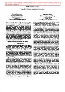
4. FlexiNET Architecture As stated in Section 1, the ForCEG is developed in the context of the FlexiNET project. The main objective of the FlexiNET project is to define and implement a scalable and modular network architecture incorporating adequate network elements (FlexiNET Node Instances) offering cross-connect control, switching/routing control, and advanced services management/access functions at the network access points that currently only support connectivity between user terminals and network core infrastructures [15], [16], [17]. The FlexiNET network architecture consists of the node instances, communication buses, and data repositories shown in Fig. 2.
Fig. 2. FlexiNET Architecture The FlexiNET UMTS Access Node (FUAN) provides functions to the FlexiNET interfaces such as switching/routing control, access to application data and service logic, etc. The FUAN complements existing access nodes (RNC, BSC) of UMTS networks. The FlexiNET WLAN Access Node (FWAN) acts both as a services access gateway (user authentication, service authorization, service discovery, etc.) and as a connection gateway between WLAN infrastructures and the FlexiNET WAN. FWAN achieves user and service roaming capabilities between different providers and service programmability using dynamic service deployment. Service programmability functions are provided over the Hitachi distributed router architecture [18], which will perform dynamic service deployment and consequently configuration of the forwarding plane using the ForCES protocol [16]. The FlexiNET Data Gateway Node (DGWN) acts as the gateway between a generic Storage Area Network (SAN) infrastructure and the FlexiNET network. It is used by
other FlexiNET instances to access subscriber (profile, location, etc) and application data required for service execution. It provides a Generic Data Interface that other FlexiNET elements may use to access data stored in the SAN. The Generic Applications Interface Bus is used for the implementation of application-related functions and the communication of information flows pertaining to the execution of application and service logic, including a framework allowing service registration, discovery and binding across the FlexiNET network. The FlexiNET Applications Server (FLAS) is a physical entity that hosts services application logic. These services are called remotely from other entities and executed locally. Using the DGWN services, the FLAS can retrieve specific information needed for services execution. The ForCEG is developed as part of the FWAN. The FWAN architecture is shown in more detail in Fig. 3: it is a distributed router consisting of two functional blocks: the basic and the extensible function blocks. The basic function block executes general packet-forwarding functions that are common to all services, e.g., it classifies received packets and handles routing table retrieval, packet switching, and node management. The extensible function block may be comprised of modules that lie in the control plane hosting control functionality e.g. OSPF routing protocols, or of modules that lie in the forwarding plane hosting packet-forwarding functions for specific protocols and services, such as packet filtering for firewalls, layer-7 processing for content switching, address translation, encryption, etc. The control plane modules are in fact the hosts of the MCPs provided that there are enough resources available. The FWAN prototype is composed of a network processor as basic functional block, and two PCs as extended functional blocks. A user will access the FWAN through an access point using either a laptop or a mobile phone. The FWAN is responsible for authenticating native and roaming users through the FLAS using an AAA Proxy.
Fig. 3. FWAN Architecture By default, the FWAN contains at least two software modules, i.e., a Dynamic Service Deployment module (DSD), which is responsible for the dynamic deployment of new services, and at least one ForCEG module. At boot-up the DSD module is responsible for dynamically deploying the AAAProxy module. The DSD module retrieves the AAA-Proxy service code through the DGWN and deploys it on one of the two PCs based on dynamic allocation algorithms. In addition, based on user profiles, the DSD module deploys a Quality of Service
Module (QoS), which is responsible for providing preferential traffic treatment to specific users. These two modules act as MCPs and issue commands to the ForCEG in order to configure the network processor to provide the functionality offered to users.
5. ForCEG Concept While the current scope of ForCES is the communication between one CE and one FE in a local area network, and the configuration of the FE by the CE, as stated in Section 3, the ForCEG extends the availability of ForCES by providing a Web Service Interface, facilitates the coexistence of multiple MCPs using a central Control Logic, and manages the state of the forwarding plane elements by staying aware of the current state of all the FEs. As stated in Section 4, any MCP may potentially be deployed on any hardware module in the FWAN, thus the API should be based on a technology that provides accessibility through a network (local or the internet). Another requirement for the ForCEG is a versatile interface, i.e., an easy-to-use and easy-to-update interface. The above requirements points towards the Web Service technology. Web services is a technology that allows applications to communicate in a platform- and programming-language-independent manner. A Web service is a software interface that describes a collection of operations that can be accessed over the network through standardized XML messaging. It uses protocols based on the XML language to describe an operation or data exchanged with another Web service. Web services technology uses XML that can describe any and all data in a truly platformindependent way for exchange across systems, thus moving towards loosely-coupled applications [19], [20]. The protocol stack that the ForCEG is based on is shown in Fig. 4. ForCES protocol messages are exchanged over TCP. Web Services use XML, which is encapsulated in SOAP messages. Any MCP must first discover the ForCEG using WSDL files, which define the endpoint of the Web Service and description of the Web Service operation, located in a registry, such as a UDDI registry 21. The MCP sends a Web Service request to the ForCEG, which attempts to translate the request into a ForCES message. When an FE wants to send a message to an MCP, the ForCEG attempts to translate the ForCES message into a Web Service response that the MCP will recognize.
Fig. 4. ForCEG Protocol Stack
In addition to translation from XML messages to ForCES messages and back, the ForCEG has a consistency-checking functionality: As it is placed between the MCPs and the hardware, it is the checking point of all exchanged messages. Messages from some MCPs may disrupt the normal functionality of other MCPs. The ForCEG monitors such messages and either informs the MCP as to which functionality is about to be changed, or disallows the message. To conceal the details of the ForCES model, higher-layer functions such as Firewall, Routing, QoS-related, etc., can be introduced and associations made between these functions and LFBs. The ForCEG can advertise the higher-layer functions in a WSDL [22] file for all MCPs to discover. The ForCEG then can recognize which LFBs the MCP needs to modify. An MCP “targets” a higher-layer function, provides the necessary attributes according to the “target” field, and then inserts an operation (such as SET or GET). The ForCEG is then able to construct the necessary ForCES messages to be sent to the appropriate LFBs. Fig. 5 depicts the “Target” concept. The ForCES FE Start/Termination Point is a necessary component for the ForCES protocol as it is the source and the destination of ForCES messages. As the QoS software module needs to setup classifier rules, it “targets” a QoS-related function, provides the necessary classification rules, and issues a SET command. A translator module inside the ForCEG will translate the attributes of the message, and a ForCES CE Start/Termination Point will transmit the ForCES message to the FE as described in Section 6.
Fig. 5. “Target” Concept In the WSDL file, an MCP can acquire data regarding the URL for calling the API, the available higher-layer functions and an XML schema that defines which kind of data types each of these higher-layer functions requires. Making ForCEG web-service enabled allows the advertisement and discovery of all the supported operations through one URL. In addition, the ForCEG is able to dynamically download other mappings between higher-layer functions and LFBs from an external source, and re-publish it to the UDDI registry. Such a dynamic configuration provides additional programmability capabilities to the ForCEG.
6. The ForCEG Architecture. This section describes the proposed ForCEG architecture realizing the concepts presented above.
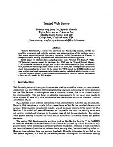
Fig. 6. Proposed ForCEG Architecture The proposed ForCEG architecture and its major architectural components is depicted in Fig. 6. The Web Services Server hosts the interfaces between the MCP and the remainder of the ForCEG. It is responsible for sending and receiving messages from different MCPs. All interfaces between MCPs and the Web Services Server are through Web Services. Besides the interfaces for sending/receiving messages from the MCPs, the Web Services Server hosts additional interfaces for interaction with a UDDI registry. This allows the ForCEG to publish its own interfaces as well as to discover interfaces of MCPs to provide packets or events back to the MCPs. Another functionality of the Web Services Server is the ability to provide dynamically downloaded interfaces from an external source in order to satisfy requirements of MCPs that require a previously unavailable higher-layer function, i.e. if an MCP requires a firewalling function that is not currently present in the ForCEG, it will request from an external source the appropriate operation and publish it for the MCP to discover. Together with the operation details, the Web Service Server will download the necessary XML to LFB mappings required by the ForCES Translator. The Message Parser is a central module that has two functions, depending on the flow of a message. If the message arrived from the MCP then the Message Parser receives the XML message from the Web Service Server, parses it, and instructs the Command Control Logic (CCL) to check the validity of the message. When it receives a positive response (i.e., a message will not create any conflict with LFB configuration), it forwards the message to the ForCES Translator. If the message arrived from the FE then the Message Parser receives the XML message from the ForCES Translator and instructs the Subscribed Events & Pending Responses (SEPR) module to identify the MCP(s) that should receive the response message(s). Once the MCP(s) has been identified, the Message Parser sends the message(s) to the appropriate MCP(s) through the Web-Service Server.
The CCL module is responsible for performing coordination functions to prevent contradictory commands from different processes. It is responsible for examining each command issued by each MCP and making sure that a new message does not affect the current functionality of existing MCPs in any way. It takes the data it requires from the “Current FE & LFBs’ state” module. The ForCES Translator module has two functions, depending on the flow of a message. If the message arrived from the MCP then the ForCES Translator receives an XML message from the Message Parser and translates the message into a ForCES protocol message that is based on the higher-layer function the MCP wants to configure. It obtains the correlation data from the “Current FE & LFB’s state” module. If the message arrived from the FE then the ForCES Translator receives a ForCES message from the FCSTP and translates the ForCES message into XML. First the ForCES translator reads the ForCES message and determines the ForCES message type (i.e. packet redirection from an FE to an MCP, notification message), in order to add an XML tag which will be identified by the Parser, and then the ForCES Translator inserts the packet into the XML message. Depending on the message type, the treatment of the packet varies. If the message is a packet redirection, the packet is encapsulated into an array of bytes in the XML message, whereas in the case of a notification message, the notification is processed and transmitted as string values. The FCSTP module has two functions depending on the flow of a message. If the message has arrived from the MCP then the FCSTP receives a ForCES protocol message from the Translator. The FSCTP is responsible for sending the message to the appropriate FEs by checking the specific field in the ForCES protocol message. If the message has arrived from the FEs then the FCSTP sends the ForCES message directly to the ForCES Translator. In addition to the message-based functions, the FSCTP has functions regarding the ForCES protocol: it is responsible to create, maintain and destroy associations with FEs. The SEPR module contains information as to which MCP any response arriving from the FE should be re-directed to. MCPs may also subscribe themselves to specific events. The event notification messages that arrive at the FCSTP are redirected to the required MCPs based on information it holds about which MCP has subscribed to which event(s). The CFLS module holds information about all of the associated FEs and their LFBs. It also needs to have all configurations of the LFBs. This data is used by both the ForCES Translator and by the Command Control Logic. 6.1. Use Case As an illustration of the functions provided by the above submodules, the sequence of events involved in the execution of a typical MCP command (packet-classification configuration command originated by the AAA Proxy) is shown in Fig. 7. When the ForCEG is instantiated it registers itself on a UDDI registry. This action occurs upon instantiation, and only when the ForCEG needs to update the registered information, i.e. when a new mapping has been downloaded. The AAA Proxy is dynamically downloaded and instantiated using methods and operations described in [23]. Once the AAA Proxy has been instantiated, it discovers
the ForCEG endpoint through an external UDDI registry as well as the required operation name and the parameters to make a valid call to the ForCEG. Once the above operations have completed, the AAA Proxy is ready to make calls to the ForCEG. The AAA-Proxy module sends a configuration message to the Web-Services Server, which passes the XML file to the Parser. The Parser reads the XML file and requests validation from the CCL that the command issued by the AAA proxy will not affect any other MCP. The CCL validates the command with regard the current state of the FE and the other MCPs configurations, and returns a response. If the response is positive, the Parser passes the XML file to the Translator. The ForCES Translator, based on the current state of the FE and the “target” of the AAA Proxy, translates the XML file into a ForCES message by correlating data from the CFLS and passes it to the FCSTP. The FCSTP receives the messages and transmits it to the appropriate FE as specified in the ForCES Destination ID protocol field. When an acknowledge response arrives from the FE, it is transmitted back to the AAA Proxy over the Web Service.
Fig. 7. ForCEG Use Case for AAA Proxy The first ForCEG prototype is being developed in Java, while the FE counterpart is being developed in C++. The ForCEG is configuring Intel’s IXP 2400 Network Processor.
7. Evaluation and Conclusion This paper has shown the issues raised by distributed router programmability and the requirements for an architecture built on top of a ForCES framework. The desire to accelerate the introduction of new services and to achieve service roaming at the edges of telecommunication networks requires the introduction of dynamic service
deployment methods as well as effective solutions to integrate services provided by ISVs, for instance. This paper has presented an architecture fitting the FlexiNET network and acting as an hourglass between ForCES-controlled forwarding-plane components and services accessing a Web Service-based interface to control the forwarding-plane datapath. The current prototype is able to create, maintain and destroy associations with FEs as well as receive simple requests from MCPs through a simple Web Service API. As the prototyping effort continues, it will help define the appropriate Web Services APIs for the relevant services in FlexiNET. Also, the effectiveness of the solution in terms of performance, versatility, and ease of use, will be evaluated. More precisely, we are interested to measure the delay to deploy and configure a new service, and the overhead incurred by our architecture as a service executes. As the FWAN at this stage is expected to operate under the complete control of a single administrative entity and that deployed services are not expected to be malicious, the security aspects have not been addressed here. However Web Services provide extensive security measures which will be evaluated in the future. Integration of other control protocols such as Netconf may extend the versatility of the ForCEG, and is an item for further research.
References 1.
Andrew Campbell, Herman De Meer, Michael Kounavis, Kazuho Miki, John Vicente, and Daniel Villela, “A Survey of Programmable Networks”, ACM SIGCOMM Computer Communications, 1999. 2. Robert Haas, Clark Jeffries, Lukas Kencl, Andreas Kind, Bernard Metzler, Roman Pletka, Marcel Waldvogel, Laurent Freléchoux, and Patrick Droz, "Creating Advanced Functions on Network Processors: Experience and Perspectives," IEEE Network, July 2003. 3. Lily Yang, Ram Dantu, Todd A. Anderson, and Ram Gopal, "Forwarding and Control Element Separation (ForCES) Framework", IETF RFC 3746, April 2004. 4. Horzmud Khosravi, and Todd A. Anderson, "Requirements for Separation of IP Control and Forwarding", IETF RFC 3654, November 2003. 5. Avri Doria, “ForCES Protocol Specification”, IETF draft, work in progress, June 2005, . 6. Lily Yang, Joel Halpern, Ram Gopal, Alan DeKok, Zsolt Haraszti, and Steven Blake, "ForCES Forwarding Element Model", IETF draft, work in progress, Feb 2005, . 7. Manasi Deval, Hormuzd Khosravi, Rajeev Muralidhar, Suhail Ahmed, Sanjay Bakshi, and Raj Yavatkar, Distributed Control Plane Architecture for Network Element, Intel’s Technology Journal, Volume 04, Issue 04, November 2003. 8. FP6-IST1 507646 FlexiNET Technical Annex, 2004. 9. Spyros Denazis, Kazuho Miki, John Vicente, and Andrew Campbell, “Interfaces for Open Programmable Routers”, First International Working Conference on Active Networks (IWAN), 1999. 10. Jit Biswas, et al., “The IEEE P1520 Standards Initiative for Programmable Network Interfaces”, IEEE Communications, Special Issue on Programmable Networks, Vol. 36, No 10, October, 1998.
11. David M. Putzolu, Network Processing Forum Software Work Group, “Software API Framework Implementation Agreement”, 2002. 12. Rensink Enns, Ed., “NETCONF Configuration Protocol”, IETF draft, work in progress, February 2005, 13. Avri Doria, Fiffi Hellstrand, Kenneth Sundell, and Tom Worster, “General Switch Management Protocol (GSMP) V3”, IETF RFC 3292, June 2002. 14. David Durham, Jim Boyle, Ron Cohen, Shai Herzog, Raju Rajan, and Arun Sastry, “The COPS (Common Open Policy Service) Protocol”, IETF RFC 2748, January 2000. 15. FP6-IST1 507646 FlexiNET D21 “Requirement, Scenarios and Initial FlexiNET Architecture”, 2004. 16. FP6-IST1 507646 FlexiNET D22 “Final FlexiNET Network Architecture and Specifications”, 2004. http://www.istflexinet.org/deliverables/FlexiNET_alcatel_wp2_d22_final.zip 17. Rodolfo L. Aladros, Christoforos D. Kavadias, Spyros Tombros, Spyros Denazis, George Kostopoulos, Jose Soler, Robert Haas, Christos Dessiniotis, and Erhard Winter, “FlexiNET: Flexible Network Architecture for Enhanced Access Network Services and Applications”, IST Mobile & Wireless Communications Summit, Dresden, Germany, 2005. 18. Tetsuhiko Hirata and Itaru Mimura, “Flexible Service Creation Node Architecture and its Implementation”, IEEE Computer Communications Workshop 2003, Oct. 2003. 19. “New to SOA and Web Services”, . 20. David Booth, Hugo Haas, Francis McCabe, Eric Newcomer, Michael Champion, Chris Ferris, David Orchard, “Web Services Architecture”, W3C Working Group, < http://www.w3.org/TR/ws-arch/>, February 2004. 21. Luc Clement, Andrew Hately, Claus von Riegen, and Tony Rogergs, “UDDI Version 3.0.2”, , October 2004. 22. David Booth and Canyang Kevin Liu, “Web Services Description Language (WSDL) Version 2.0 Part 0: Primer”, W3C Working Draft, May 2005, http://www.w3.org/TR/2005/WD-wsdl20-primer-20050510/ 23. Christos Chrysoulas, Evangelos Haleplidis, Robert Haas, Spyros Denazis, Odysseas Koyfopavlou, “Applying a Web-Service-Based Model to Dynamic Service-Deployment”, to be published at the International Conference on Intelligent Agents, Web Technologies, and Internet Commerce (IAWTIC), November 2005.