1080
IEEE TRANSACTIONS ON COMPUTER-AIDED DESIGN OF INTEGRATED CIRCUITS AND SYSTEMS, VOL. 22, NO. 8, AUGUST 2003
PROPTEST: A Property-Based Test Generator for Synchronous Sequential Circuits Ruifeng Guo, Member, IEEE, Sudhakar M. Reddy, Fellow, IEEE, and Irith Pomeranz, Fellow, IEEE
Abstract—We describe a property-based test generation procedure for synchronous sequential circuits. Several techniques are used to generate test sequences that achieve high fault coverages at low computational complexity. These include the use of static test compaction, input vector holding with optimal numbers of hold cycles, input vector perturbation, and identification of subsequences that are useful in extending the test sequence. Experimental results presented demonstrate that the proposed procedure achieves fault coverages which are in all cases the same or higher than those achieved by existing procedures. Index Terms—Automatic test pattern generation (ATPG), sequential circuit, test compaction, test generation.
I. INTRODUCTION
G
ENERATION of tests to detect faults in synchronous sequential circuits is a challenging problem. Scalable methods to perform test generation have been under study for many years. The existing methods can be classified into four categories. The first category of methods uses the branch and bound technique to derive tests for target faults [1]–[6]. The second category uses fault simulation to direct the search for a test sequence for the target faults [7]–[13]. Included in this category are genetic optimization-based test generation procedures. The third category uses certain observed properties of test sequences in deriving input sequences that have similar properties, and are useful as test sequences [14], [15]. The fourth type of methods are based on pseudorandom or special purpose test generator circuits that produce effective test sequences [16]–[18]. These methods are often meant for use in built-in self-test environments. Fault simulation-based and property-based test generators have the advantage that they can be adapted to new fault models or circuit descriptions (e.g., register transfer level instead of gate level) with minimal effort by using a fault simulator suitable for the new fault model and/or circuit Manuscript received June 19, 2002; revised January 20, 2003. This work was supported in part by the National Science Foundation under Grant MIP9725053 and in part by the Semiconductor Research Corporation under Grant 98-TJ-645. This paper is based on the following papers authored by R. Guo, S. M. Reddy, and I. Pomeranz: “A Fault Simulation Based Test Pattern Generator for Synchronous Sequential Circuits,” Proc. 17th VLSI Test Symp., Apr. 1999, pp. 260–267; “On Improving a Fault Simulation Based Test Generator for Synchronous Sequential Circuits,” Proc. 10th Asian Test Symp., Nov. 2001, pp. 82–87. This paper was recommended by Associate Editor R. C. Aitken. R. Guo is with the the Diagnosis Technology Department, Intel Corporation, Hillsboro, OR 97124 USA (e-mail:
[email protected]). S. M. Reddy is with the Department of Electrical and Computer Engineering, University of Iowa, Iowa City, IA 52242 USA. I. Pomeranz is with the School of Electrical and Computer Engineering, Purdue University, West Lafayette, IN 47907 USA. Digital Object Identifier 10.1109/TCAD.2003.814953
description. The existence of asynchronous elements in circuits can also be accommodated. Recent efforts in developing fault simulation-based test generators have mostly used genetic optimization techniques to engineer test sequences for target faults [9]–[12]. One such procedure [12] has recently achieved high fault coverage, but requires large computational effort. The property-based test generator reported in [14] uses only logic simulation in deriving a test sequence whose coverage is determined by fault simulation. The run time of this method is small but as of now it has not achieved as high a fault coverage as the genetic optimization based test generation procedures. The test generation method we present in this paper is a combination of fault simulation-based and property-based test generation approaches. In Section II, we discuss the relationship of the proposed procedure to these approaches and discuss the observations that led to the development of the proposed procedure. We demonstrate that the procedure achieves high fault coverage with relatively low computational effort by taking advantage of several techniques. Since the procedure does not use deterministic test generation steps such as implication or branch and bound, it does not identify undetectable faults. This drawback exists for all of the simulation-based and property-based test generators that do not use any deterministic test generation. The paper is organized as follows. In Section II, we describe the motivation for the proposed procedure. In Section III, we study several different methods to generate test sequences that employ the observations made in Section II. The results of this study are used in designing the procedure described in the later sections. In Section IV, we give an overview of the implemented procedure. A detailed description of this procedure is given in Section V. In Section VI, we provide experimental results for the proposed test generator. Section VII summarizes this paper. II. MOTIVATION The proposed test generation procedure is inspired by the following observations and recent results related to test sequence generation for synchronous sequential circuits. (i) The lengths of the test sequences generated by a variety of test generators can be reduced quite significantly (over 50%) by static compaction procedures that omit test vectors from the test sequences [19]. This reduction in test length is achieved without loss of fault coverage. Since static test compaction reduces the test length without reducing the fault coverage, one may argue that static test compaction retains useful vectors while omitting other vectors in order to reduce the test length. Thus, the compacted test sequence can be regarded as being of “higher
0278-0070/03$17.00 © 2003 IEEE
GUO et al.: PROPTEST: PROPERTY-BASED TEST GENERATOR FOR SYNCHRONOUS SEQUENTIAL CIRCUITS
quality” than the sequence before compaction. If the fault coverage of a given test sequence is not maximum, then static compaction often results in a shorter test sequence with fault coverage higher than that of the given sequence [19]–[21]. This again implies that static compaction enriches the quality of the test sequence. Thus, one may argue that static compaction implicitly captures circuit properties desirable to generate effective test sequences. It should also be observed that test sequence compaction is probably a necessary step for generating short test sequences for sequential circuits if deterministic test generation is not extensively employed. (ii) Genetic optimization has been used successfully to obtain test sequences with high fault coverage [11], [12]. The basic steps in genetic optimization are mutation and crossover. Mutation is the process of complementing bits in a given sequence. The earliest sequential circuit test generator of [7] also used complementation of bits of a given sequence (e.g., a functional test sequence) to derive new sequences that detect other faults and/or to improve the fault coverage of a given sequence. Recent work reported in [17] showed that tests for combinational circuits can be derived by perturbing a small number of tests called “centers.” The studies discussed above indicate that perturbation is a useful technique to derive new tests from already derived tests. (iii) In [16], it was observed that holding the inputs of a sequential circuit at fixed values for several clock cycles improves the fault coverage obtained by a pseudorandom sequence generated, for example, by a linear feedback shift register. In this approach, an input vector generated by a pseudorandom pattern generator is held for a predetermined number of cycles. In terms of state traversal, holding the inputs constant makes the circuit traverse potentially different states appearing in the state table under the column corresponding to the held input vector. In several other works [12], [14], it was observed that test sequences that traverse large numbers of states were effective in detecting faults. In [16], the number of clock cycles during which inputs are held are determined by running a deterministic sequential circuit test generator over a sample of faults. Thus, an effective deterministic sequential circuit test generator is necessary to supplement the method of holding of pseudorandom input vectors reported in [16]. In our use of input holding, we determine the number of cycles to hold an input vector without using a deterministic sequential test generator. Instead, we use a procedure based on state information to determine the number of hold cycles. (iv) Weighted random test pattern generation has been demonstrated to be effective in achieving high fault coverages for combinational logic circuits [22], [23]. A hill-climbing method where the input probabilities for new weighted random vectors are determined from the set of test vectors which detected the most recent faults was demonstrated to achieve high fault coverages [24]. This work suggests that the input probabilities of randomly generated vectors to detect additional
1081
faults can be set according to the tests generated for the detected faults. A similar idea was used in [25] to derive weighted random test patterns from the input probabilities computed over a deterministic test set. For sequential circuits, the input probabilities of weighted random sequences to detect additional faults can be derived from the test sequence of the already detected faults. From observation (i) made above, that compacted test sequences may capture desired properties of test sequences, it can be argued that input probabilities computed over compacted test sequences may be more effective. Summarizing, the experimental results presented in several recent works indicate that static test compaction based on omitting vectors from a test sequence to capture circuit properties, perturbation, and holding of inputs constant in a test sequence may lead to a more effective test sequence. It should, however, be noted that an automatic test pattern generation (ATPG) employing perturbation and/or input holding that achieves high fault coverages has not been demonstrated earlier. Similarly, static test sequence compaction has been used to reduce the length of a given test sequence, but not to improve the computational efficiency of a test generator or to achieve high fault coverage. In this work, we use static test compaction, perturbation, and input holding together to produce an ATPG tool that is highly efficient and effective in achieving a high fault coverage. In addition, we also extract test subsequences with useful properties and repeat them with certain modifications in order to detect additional faults. III. DIFFERENT METHODS TO GENERATE TEST SEQUENCES In order to choose an efficient way to generate test sequences based on the observations made in the previous section, we conducted experiments to study the relative effectiveness of several test sequence generation procedures. The first experiment was conducted to determine whether holding a random input vector a randomly selected number of times improves the fault coverage of a random sequence of a given length. We also wanted to determine if test sequence compaction further improves the fault coverage of such a random sequence. The results of this experiment are reported in Table I. For all of the benchmark circuits reported in Table I, we set the length of the test sequence used to 300 000. Under the column “Total,” we list the total number of collapsed faults for each circuit. We report in Table I the number of faults detected using various methods. The test sequence generation methods used are described below. A. Method R A random sequence of the given length is generated with the probability of one on every primary input set to 1/2. B. Method RH A sequence of random vectors as in Method R is generated, except that every vector is held for a number of time units. The number of time units a vector is held is randomly selected as
1082
IEEE TRANSACTIONS ON COMPUTER-AIDED DESIGN OF INTEGRATED CIRCUITS AND SYSTEMS, VOL. 22, NO. 8, AUGUST 2003
TABLE I EFFECT OF COMPACTION ON NUMBER OF FAULTS DETECTED
follows. An input vector is held for time units with probability , for , and it is held for time units with . probability C. Method RHC(N) A sequence, say , of length is generated using method RH. It is then compacted using the linear reverse order restoration based static compaction procedure linear reverse order restoration (LROR) described in [21] into a sequence . Next, is extended into a sequence of length again the sequence using by concatenating a sufficient number of vectors to the sequence generation Method RH. These steps are repeated until the total number of vectors generated reaches 300 000. We used two values of , 3000 and 5000. These are reported as RHC(3000) and RHC(5000) in Table I. The total number of faults detected in all of the circuits by each method is reported in the last row of Table I. The following observations can be made by noting the total number of detected faults reported in Table I. (i) By comparing Methods R and RH, it can be observed that, for most circuits, holding a random vector a random number of times improves the fault coverage over that obtained by a random sequence of the same length. (ii) By comparing Methods RH and RHC(N), it can be observed that compacting a sequence after every test vectors helps increase the fault coverage. Furthermore, comparing the results for RHC(3000) and RHC(5000) it can while keeping be noted that increasing the value of the total test sequence length constant leads to the detection of additional faults. One can argue that the reason
for compaction improving the fault coverage is that the compacted prefix of a test sequence of length drives the sequential circuit into the states that are more effective for fault detection. The reason for the increase in fault coverage with increased value of is, we believe, due to the fact that longer subsequences are more likely to detect harder to detect faults. In all of the methods reported in Table I, additional test vectors were randomly generated. In the next experiment, we wanted to determine the relative effectiveness of different methods that use the properties of the compacted test sequences in generating additional vectors. We evaluated eight methods to generate test vectors, and we report the number of faults detected by these methods in Table II. The different methods used are described next. The basic steps used in all of the methods reported in Table II and are the same as those used for RHC(N) with these are: Step 1: Generate a random sequence of length 5000. Set iteration count . (We will perform 60 iterations to guarantee that no more than 300 000 vectors are generated as before). Step 2: Compact the test sequence into by using the test a sequence sequence compaction procedure LROR described in [21]. Simulate the compacted test sequence and drop the faults detected from the fault list. is less Step 3: If the iteration count into a sequence than 60, extend of length 5000, using one of the different extension techniques(described below) and go to Step 2. Step 4: Return the number of faults detected by the final test sequence. The various test sequence generation methods employed differ in the manner the compacted test sequence is extended into in Step 3 given above. D. Method E Compute the proportions of 1s and 0s on each primary input among the vectors in the compacted sequence . Use these proportions as probabilities of 1s and 0s on the primary inputs in Step 3 above. to generate new vectors to extend E. Method EH is the This method of generating new vectors to extend same as Method E, with the exception that a vector generated is held a random number of times as discussed for to extend Method RH described earlier.
GUO et al.: PROPTEST: PROPERTY-BASED TEST GENERATOR FOR SYNCHRONOUS SEQUENTIAL CIRCUITS
1083
TABLE II EFFECT OF DIFFERENT TEST GENERATION METHODS ON NUMBER OF FAULTS DETECTED
F. Method EPH is the This method of generating new vectors to extend same as Method EH, except that a new vector generated is first perturbed before holding it a random number of times. The method used to perturb a vector is the same in all of the methods reported in Table II and is described in Section V. G. Methods En, EnH, and EnPH These methods are analogous to Methods E, EH, and EPH, respectively, except that the probabilities of 1s and 0s on the primary inputs are computed by considering only the subsequence over which the most recently detected faults are detected. of We set a limit of 100 on the length of the subsequence used to compute input probabilities in these methods. H. Method VPH in Step 3 above are generated The new vectors to extend by randomly selecting a vector from , followed by randomly perturbing it and then holding it a random number of times. I. Method SPH are generated similar to the The new vectors to extend Method VPH, except that we either select a single vector with probability 5/6 or a subsequence of length 5 with probability 1/6, before perturbing and holding. If a subsequence of length 5 is selected then we do not hold it. The number of faults in benchmark circuits detected by the eight methods described above and the total number of faults detected in all of the circuits are given in Table II. We also listed the total number collapsed faults for all of the circuits under
column “Total” in Table II. Comparing the results reported we can make the following observations: (i) All of the methods use some property of the compacted test sequence. In the first six methods, the probabilities of 1s and 0s in new test vectors are set equal to the proportions of 1s and 0s on each primary input in the compacted sequence or in a subsequence of . In the last are used. All of two methods, the actual vectors in these methods detect larger numbers of faults than the methods where primary input vectors are generated randomly (the methods reported in Table I). Thus, one can conclude that test sequence compaction identifies properties, or test vectors, effective in fault detection. Furthermore, repeated use of test sequence compaction appears to help update properties of the compacted sequence that are effective in detecting additional faults. (ii) Comparing the number of faults detected by methods that use vector perturbation and holding with those that do not, one can conclude that vector perturbation and vector holding increase the number of faults detected. (iii) Comparing methods E, EH, and EPH to En, EnH, and EnPH, respectively, it appears that deriving input properties based on the subsequences that detected the most recently detected faults is more effective than deriving input probabilities based on the entire compacted test sequence. (iv) Comparing the results for Method SPH with those for Method VPH, it appears that subsequences of already generated test sequences help detect additional faults as was also observed in [15]. (v) All of the methods studied in Table II achieve similar fault coverages and, hence, may have the potential to
1084
IEEE TRANSACTIONS ON COMPUTER-AIDED DESIGN OF INTEGRATED CIRCUITS AND SYSTEMS, VOL. 22, NO. 8, AUGUST 2003
, and copies of are included in consecutive positions of (inclusion of copies of corresponds to holding the inputs for cycles). The constant at is determined as exvalue of plained below. In the other procedure, a subsequence of length is chosen from as explained below. The subsequence is placed . The first procedure is in and the used with probability second procedure is used with ). The extension probability ( into by adding vectors of continues until to the suffix reaches a predethe length of termined value. and go to Step 2 Step 6: Set
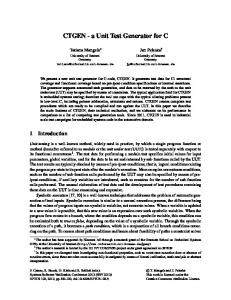
Fig. 1.
Sequential test pattern generation procedure.
achieve the highest achievable fault coverages if a test generator is built using appropriate values for the various parameters used in each method. We report in the next two sections a test generator we built using Method SPH. IV. OVERVIEW OF THE PROPOSED PROCEDURE Fig. 1 shows the six basic steps of the proposed ATPG system. The ATPG steps are explained below. Step 1: Generate a random input sequence of length . Set . on the circuit Step 2: Fault Simulate be the set of under test. Let faults detected by input sequence . Step 3: Use static test sequence comto obtain a compaction on whose pacted test sequence fault coverage is the same as that or higher, i.e., detects of and posall of the faults in sibly additional faults. Step 4: Check the termination condition. If satisfied, stop. by appending a suffix Step 5: Extend to obtain an input sequence . The suffix is obtained by repeatedly using one of the following two procedures. in In one procedure, a vector is randomly chosen. It is randomly perturbed to obtain a vector
The example given next illustrates the steps in the proposed procedure. A. Example Consider a sequential circuit with two primary inputs. Assume that the length of the sequence in Step 1 above is chosen to be four and the lengths of the extended sequences in Step 5 is chosen to be 11. Let the random input sequence generated . Let the sequence obtained in Step 1 be be . after applying static compaction to Static compaction dropped one vector from (the third vector) . Next, we extend into by concatenating to obtain to obtain a sequence of the desired eight more vectors to length (eleven) by executing Step 5. Suppose that in the first into , input vector (11) is picked procedure for extending . Next, we randomly perturb it by complerandomly from menting the second bit to obtain (10). We then pick a random number of repetitions for (10), say two repetitions. This will into the sequence (00, 01, 11, 10, extend 10). Next, suppose that we randomly pick the subsequence (01, . We concatenate this subsequence to (00, 01, 11, 11) from 10, 10) and obtain a length seven sequence (00, 01, 11, 10, 10, 01, 11). Next, let us again pick randomly a subsequence . We concatenate this subsequence to (00, (00, 01) from 01, 11, 10, 10, 01, 11) to obtain the length nine sequence (00, 01, 11, 10, 10, 01, 11, 00, 01). Suppose that we next pick ranand randomly perturb both bits domly the vector (00) from to obtain (11). We randomly decide to hold this vector three times. However, since the extended sequence length is set to eleven, we concatenate only two copies of (11) to (00, 01, 11, 10, 10, 10, 01, 00, 10) to obtain a length eleven sequence . and then apply static compaction Next, we fault simulate to it. Suppose that after application of static compaction, we obby dropping six tain a test sequence into and iterate compaction vectors from . We extend and extension until the procedure termination condition is met.
GUO et al.: PROPTEST: PROPERTY-BASED TEST GENERATOR FOR SYNCHRONOUS SEQUENTIAL CIRCUITS
V. DETAILED DESCRIPTION OF THE TEST GENERATION PROCEDURE In this section, we give the details of the proposed test generation procedure. As noted in the overview, we use test compaction and test sequence extension (Steps 3 and 5 in the procedure overview given in Section IV) repeatedly to generate test sequences. Let be an be the corresponding compacted seextended sequence and quence obtained by the application of the static test compaction procedure. Next, we give the parameters used in each step of the procedure together with a detailed explanation of each step. We refer to the various steps in the overview when discussing these details. A. Steps of the Procedure Step 1: In this step, we generate a seof length 2000. The iniquence tial part of this sequence is a synchronizing sequence for the fault-free circuit if one exists, and the rest of the sequence is randomly generated. The generation of a synchronizing sequence is described in Section V-D Step 2: Assuming that the power-up state of the circuit is unknown, the is fault simulated sequence using the fault simulator HOPE [26], [27]. The fault simulator HOPE is used in our work whenever we need to fault simulate a sequence. is compacted to Step 3: The sequence using the obtain the sequence LROR static compaction procedure described in [21]. Step 4 (Procedure termination): The test generation procedure is terminated when three consecutive extended sequences do not detect any as-yet undetected faults. A limit of three extended sequences provides a good tradeoff between fault coverage and test generation time. However, a user may choose a different number. Step 5: In this step, a compacted sequence is extended to obtain a longer . sequence
In order to ensure the ability to generate vectors with few 1s and also vectors with large numbers of 1s in them, we append before it is expanded into five all-0 and five all-1 vectors to . When an all-0 (all-1) vector is picked during sequence extension, perturbation creates a vector with few 1s (large number of 1s). We found that, overall the use of the all-0 and all-1 vec-
1085
tors helps reduce the run times and improve the fault coverages achieved. We extend by randomly selecting either single vectors or . We tried different numsubsequences of length five from bers of probabilities, e.g., 1/2, 1/3, 1/4, 1/5, and 1/10, to select a subsequence and found that 1/6 performs the best overall on the available benchmark circuits. The probability of selecting a subsequence of length five is set at 1/6 in our implementation. We use lengths of 2000, 5000, 10 000, 20 000, and 40 000 for the extended sequences. Initially, the extended sequence length is set at 2000. Whenever two consecutive extended sequences do not detect any yet undetected faults we increase the length to the next higher value (if one exists). We start with small test sequences, which quickly detect the easily detectable faults, and later, we use longer test sequences to tackle the hard-to-detect faults. For the random pattern testable circuits, this can reduce test generation time if all of the detectable faults are detected before we reach the 40 000 lengths. For the random pattern resistant circuits, more iterations of the compaction/extraction process in the beginning can quickly extract the circuit properties, and the extracted properties will be used by the longer test sequence lengths to detect more faults. If a single vector is selected (and not a subsequence), we perturb the vector in zero or one or two or three bits with equal probability. We used different perturbation rates in our experiments, and found that perturbing no more than three bits works better for most circuits. Thus, the probability that a vector is actively perturbed by complementing some bits is 0.75 in our procedure. This is much higher than the probability of mutation used in genetic optimization procedures. However, we do not perturb more than three bits in each vector. The bit positions perturbed are determined randomly. After obtaining the perturbed vector, we decide on the number of times this vector is copied into consecutive positions of the extended sequence. This step is used to achieve holding of inputs constant at a specific vector. We describe the selection of the number of hold cycles in Section V-B. , then it is included in If a subsequence is selected from the extended sequence without holding it. The selection of subsequences is described in Section V-C. Additional Details: Initial iterations of the procedure use a sample of 128 randomly selected faults as targets for test generation. The compaction process is slower if more faults are targeted at the very beginning. The gradual fault injection process reduces the overall test generation time. Each time when an extended sequence does not detect any yet undetected fault in the fault sample, the sample size is doubled and new faults are added to the fault sample. As faults are detected, the fault sample is replenished by selecting additional undetected faults. This process continues until all of the yet undetected faults are targeted in the later iterations of the procedure. B. Determining the Number of Hold Cycles In this section, we first give the results of an experiment to guide the selection of the number of hold cycles to be used for a circuit under test. Based on the observations from the results of this experiment, we propose a method to calculate optimal hold cycle lengths for the circuit under test.
1086
IEEE TRANSACTIONS ON COMPUTER-AIDED DESIGN OF INTEGRATED CIRCUITS AND SYSTEMS, VOL. 22, NO. 8, AUGUST 2003
TABLE III COMPARING HOLDING SEQUENCES AND PSEUDORANDOM SEQUENCES
1) Experiment to Determine the Number of Hold Cycles: The two reasons given below were suggested for the success of the hold method initially suggested in [16]. Reason 1: Holding a vector for multiple clock cycles can help to propagate the fault effects latched in the flip-flops to the primary outputs. Reason 2: Once a hard-to-activate fault is accidently activated by a random vector, by holding this vector for multiple cycles, the fault can be activated during multiple cycles and, hence, the possibility of observing the fault at primary outputs and propagating the fault effect to flip-flops is increased. Based on the reasons given above, in [16], the numbers of hold cycles were determined by analyzing deterministic test sequences generated for a set of sampled faults in the circuit under test. In this work, we chose the number of hold cycles based on the results of logic simulation of a short random sequence applied to the fault-free circuit. The reasons for the method used in this work are based on the results of the following experiment. This experiment is conducted to study the effect of the holding sequences and to compare them to the pseudorandom sequences. We used several ISCAS’89 benchmark circuits and ITC’99 benchmark circuits and several circuits synthesized from high-level descriptions. In this experiment, for each circuit under test, four sequences , . The length are generated, they are denoted as , , is a pseudorandom seof each sequence is 40 000. Sequence is quence, which contains 40 000 unique vectors. Sequence a sequence by holding each randomly generated test vector 8 clock cycles before we change to the next randomly generated test vector. In this sequence, the number of unique test vectors and are sequences by is 5000 (40 000/8). Similarly, holding a randomly generated test vector 64 and 512 clock cycles, respectively, and the total number of unique vectors in and are 625 and 79, respectively. In the following, the seis referred to as pseudorandom sequence, while sequence , are referred to as “holding sequences”. quences , may be different. The vectors included in Fault simulation is conducted for each test sequence and the fault simulation results are collected in Table III. For each test sequence, we list the number of unique states traversed
by the good machine(#S), the number of detected faults(#F), the number of flip-flops which have been set to 1(#1) or 0(#0) in the good circuit. From the data in Table III, we have the following observations. (1) Generally, the holding sequences can set more flip-flops to 1 or 0 than pseudorandom sequences, even though the holding sequences have fewer unique vectors and the number of unique states traversed by the holding sequences are not necessarily higher than the pseudorandom sequences. (2) For most circuits, the holding sequences detect more faults than pseudorandom sequences. However, there are also circuits where the holding sequences do not show any advantage over the pseudorandom sequences. (3) For circuits where holding sequences have an advantage over pseudorandom sequences, different numbers of hold cycles show different effectiveness. The maximum number of faults are detected for hold cycle values that also lead to higher numbers of flip-flops set to 0 and 1. From the above observations, we can conclude that by setting more flip-flops to 1 and 0, holding sequences also detect more faults. This may be related to the fact that the holding sequences drive the good machine to traverse more hard-to-reach states. These hard-to-reach states are necessary to activate the hard-to-detect stuck-at faults. We also observed that not all of the circuits need holding of input vectors. These circuits are generally random pattern testable circuits and pseudorandom sequences perform the best in terms of fault detection and good machine state traversal in these circuits. This explanation for the success of holding sequences can also be supported by the work in [30], where the authors observed that a deterministic sequential circuit ATPG spends most of its time justifying states which are necessary to activate target faults while only a small fraction (about 10%) of its CPU time propagating fault effects to the primary outputs. It can be concluded that the complexity of the detection of a (hard-to-detect) fault comes from its activation, which needs specific values on some flip-flops. 2) Optimal Hold Cycle Lengths and Truncation of Hold Cycles: Based on the above analysis, we propose a method to determine the numbers of hold cycles for a given circuit. In the
GUO et al.: PROPTEST: PROPERTY-BASED TEST GENERATOR FOR SYNCHRONOUS SEQUENTIAL CIRCUITS
work reported here, two numbers of hold cycles will be used for every circuit under test. In order to obtain these numbers, logic simulation of the fault-free circuit is utilized to obtain the sequence of states that the circuit traverses under sequences constructed using different numbers of hold cycles. The best two numbers of hold cycles, that result in sequences which set more flip-flops to 1 and 0, are selected as the optimal numbers of hold cycles. In case of a tie, the number which causes the circuit to traverse more states is selected. In the case where there is still a tie, we select the smallest value among the tied values. While deciding how many cycles to hold a selected vector, the two selected numbers of hold cycles are given different probabilities. In our experiments, we tried several different probabilities, and selected the one which gives the best results for most benchmark circuits. In our implementation, the one which leads to the most flip-flops being set to 1 and 0 (or the one that leads to the largest number of states in case of a tie) is given a probability of 75%, while the other is given a probability of 25%. We use eight prespecified numbers as candidate numbers of , 2, 4, 8, 16, 64, 128, 512. Parhold cycles. These are allel pattern logic simulation is implemented and four bits out of each 32-bit computer word are allocated to each value of . For example, bits 0, 8, 16, and 24 are allocated to sequences , bits 1, 9, 17, 25 are allocated to sequences with with , and so on. For each value of , the total number of simulated test vectors is 10 000, which results in 2500 runs of parallel pattern logic simulation. For example, after logic simulaset the most tion of 10 000 vectors, if the sequence with set the flip-flops to 1 and 0, while the sequence with second highest number of flip-flops to 1 and 0, during test generation, we use hold cycle numbers 1 and 64. In this example, we give the hold cycle number 1 a probability 75% and give the hold cycle number 64 a probability of 25%. Even though for some circuits we use a large number of hold cycles , it is not necessary to hold every vector for clock cycles. For example, in the following holding sequence, through are generated by holding a vector .
Suppose that logic simulation yields the good machine states through . If state is the same as state , then state will also be the same as , where and . In this case, the states traversed by the good machine after vector repeat the states traversed by vectors through , and no new states are introduced after time unit . As observed in [14], the more states the good machine traverses, the more likely it is that new faults will be detected. We used a technique called hold truncation to avoid holding an input vector when this will lead to repeated good machine states. During simulation of the extended sequence, once we find that a state reappears while holding a vector, we stop holding the same vector and select a new one. In this way, the number of traversed states is increased. The increased number of traversed states leads to the detection of more faults.
1087
C. Subsequence Template In this section, we discuss the method to select a subsequence used to extend the compacted sequence. Two procedures are involved in finding the subsequences to be concatenated at the end of a compacted sequence in order to extend it in Step 5. The first procedure finds the hard-to-reach values of flip-flops through logic simulation. Once a flip-flop is found to have a hard-to-reach value, a subsequence which can preserve the value of the flip-flop is identified by the second procedure. The subsequence is relaxed by unspecifying some input values and the relaxed subsequence is saved for use during the extension of . 1) Hard-to-Reach Values of Flip-Flops: During logic simulation to determine the optimal number of hold cycles, we keep the number of times each flip-flop is set to “1” and “0.” For each flip-flop, the hard-to-reach value is defined as follows. Let the total number of simulated vectors be and let the ( ). number of vectors which set flip-flop to 1(0) be if We say that 1 is a hard-to-reach value of flip-flop . Similarly, we say that 0 is a hard-to-reach value . of flip-flop if Obviously, if a flip-flop cannot be initialized to a binary value, both 1 and 0 are hard-to-reach values for the flip-flop. Once the hard-to-reach values of the flip-flops are determined, they are stored as a linked list which is called the “monitored list.” The items in the monitored list are pairs consisting of a flip-flop and its hard-to-reach value (flip-flop, ). 2) Subsequence Identification and Relaxation: During the generation of the extended sequence, after each vector is added to the sequence, the vector is simulated. After simulating each vector, the items in the monitored list are checked. If a hard-toreach value is found for any flip-flop, we identify and relax the subsequence which leads to the hard-to-reach value starting from the unknown initial state. We use a method based on the concept of “supporting region” to find a relaxed subsequence that sets the hard-to-reach value on the flip-flop. The technique of finding the supporting region of a gate was presented in [28] and [29], and was called the star algorithm. Given a gate and its simulated value , to find the supporting input of , we first put a star on the output of gate . If there are inputs with the controlling values of gate , we mark one of them with a star (0 is the controlling value of an AND/NAND gate and 1 is the controlling value of an OR/NOR gate). If none of the inputs has the controlling value of gate , all of the inputs are marked with a star. For each input of gate marked with a star, the star algorithm continues to mark its supporting inputs. At any time frame, if the output of a flip-flop is marked with a star, the star algorithm will continue to the previous time frame by backtracing from the corresponding flip-flop inputs. All of the gates with stars on their inputs compose the supporting region of gate . If a primary input is marked with a star, its value should be kept. If a primary input is not marked, its value does not affect the value of gate and it can be relaxed to a don’t care “X.” The relaxed subsequence obtained in this way is stored for use during the process into . We refer to a relaxed subsequence as a of extending subsequence template.
1088
IEEE TRANSACTIONS ON COMPUTER-AIDED DESIGN OF INTEGRATED CIRCUITS AND SYSTEMS, VOL. 22, NO. 8, AUGUST 2003
The following is the procedure to generate the subsequence template. The procedure limits the length of the extracted subsequence to be at most a constant MAXLENGTH. Procedure Subseq_Identification_Relaxation() (1) Logic simulate the subsequence ending with the vector which set the flip-flop to its hard-to-reach value. Start the simulation either at time unit 1 or at a time unit such that the length of the simulated subsequence is at most MAXLENGTH. Store the state after simulating each test vector. (2) If the hard-to-reach value of the flip-flop is not preserved by the subsequence, return FAIL. (3) Using the star algorithm, find the supporting region of the hard-toreach value of the flip-flop. (4) For each primary input which is not marked with a star, set its value to a don’t care, “X.” (5) Save the relaxed subsequence from Step (4) and return SUCCESS. During the sequence extension process in Step 5 of the test generation procedure, if a subsequence is selected to extend the sequence, a relaxed subsequence is randomly selected from the stored subsequence templates, the don’t care values (Xs) in the relaxed subsequence are randomly filled with binary values, 1 or 0, and the resulting subsequence is copied into the extended sequence. D. State-Driven Circuit Initialization Synchronizing sequences that drive the good machine from the all of unknown state to a specific known state are useful for fault detection. Some of the most recently developed test generators [12], [31] use synchronizing sequences as prefixes of test sequences. Generally, a method which selects one vector from a group of candidate vectors that can set more flip-flops to a binary value is used. However, in some cases, this procedure may not synchronize a circuit. For example, consider a circuit with an 8-bit counter and some other memory elements. Suppose that only when the 8-bit counter is in the all-1 state, the other flip-flops will be set to binary values. If there is a primary input to reset the counter to zero, then we have to avoid the activation of the reset signal during the process of driving the counter to the all-1 state. One way to achieve this goal is to identify the counter, the condition for synchronizing the other flip-flops, and the necessary condition for driving the counter from the reset state to the all-1 state. This may need an analysis over a large sequential depth which may be beyond the normal capabilities of a deterministic sequential circuit test generator.
We propose a method called state-driven circuit initialization that initializes efficiently a broader class of circuits than the random vector selection method described above. In this method, from a group of candidate vectors, we try to select the one which can set more flip-flops to binary values. In case of a tie, we select the first one which drives the good machine to a nontraversed state. We found that the criterion of choosing an input vector that drives the circuit to new states helps to initialize several circuits that the random vector selection method alone cannot initialize. It avoids complex deterministic analysis and is very effective in synchronizing circuits where it is necessary to drive some flip-flops to a specific state in order to initialize all of the flip-flops in the circuit. For example, the circuit write_e [33] cannot be synchronized by HITEC [4] and STRATEGATE [12] and, hence, these procedures achieve low fault coverage (around 13%). However, if we use the proposed initialization method, this circuit can be initialized quickly and the fault coverage will be 83.7%, which is an improvement of 70% in fault coverage. VI. EXPERIMENTAL RESULTS The test pattern generator described in the previous sections, referred to as PROPTEST, was implemented in the C language. The run times reported for the proposed test generator are measured on a machine with a 400-MHZ Pentium II processor and using the LINUX operating system. Run times are given in seconds. The circuits used in this study are the larger ISCAS’89 benchmark circuits, the ISCAS’93 addendum circuits, and the synthesized circuits available from the University of Illinois. The results are reported in Tables IV–VI. After the circuit name, we report the fault coverages and the test sequence lengths in Tables IV–VI. In Table IV, the first column under “Fault Coverages” shows the fault coverages achieved by PROPTEST and the second column shows the test efficiency of PROPTEST when the procedure of [32] is used to identify the untestable faults. In Tables V and VI, we give the total number of collapsed faults in the circuits in column two followed by the fault coverage and test efficiency achieved by PROPTEST. In Tables IV–VI, we also list the fault coverages achieved by other test generators when the results are available. For all of the 45 benchmark circuits in Tables IV–VI, PROPTEST achieves the same or higher fault coverages compared to all of the other test generators. For some circuits, it is the first time these highest known fault coverages are reported, e.g., for div16, s3384, b12, b22, and write_e. It should be noted that for ISCAS’89 circuits, most of the ADDENDUM’93 circuits and the synthesized circuits am2910, mult16, pcont2, piir8, and piir8o, the fault coverages achieved are the maximum possible using three valued simulation used in this work. The same fault coverages were also achieved by other test generators such as [12] and [35]. For most of the remaining benchmark circuits PROPTEST achieves the highest fault coverages. Test sequence lengths are also reported in Tables IV–VI. When comparing with other test generators, for most circuits PROPTEST achieves higher fault coverages with shorter test sequences when the fault coverages are comparable. One reason for the short sequences generated by PROPTEST is
GUO et al.: PROPTEST: PROPERTY-BASED TEST GENERATOR FOR SYNCHRONOUS SEQUENTIAL CIRCUITS
1089
TABLE IV TEST GENERATION RESULTS FOR BENCHMARK CIRCUITS
TABLE V TEST GENERATION RESULTS FOR ITC’99 CIRCUITS
TABLE VI TEST GENERATION RESULTS FOR SYNTHESIZED CIRCUITS
that PROPTEST uses a compaction technique during test generation while the other test generation programs do not have built-in compaction mechanism. Note that even though PROPTEST uses compaction techniques during test generation, its test sequences may be further compacted using other test compaction techniques [36].
For several circuits, e.g., div16, b15, b20, b21, and b22, PROPTEST achieves higher fault coverages than other test generation methods at the cost of much longer test sequences. This leads to the following observations. Some faults in these circuits are hard-to-detect faults and their detection requires some hard-to-reach circuit states. PROPTEST performs much
1090
IEEE TRANSACTIONS ON COMPUTER-AIDED DESIGN OF INTEGRATED CIRCUITS AND SYSTEMS, VOL. 22, NO. 8, AUGUST 2003
TABLE VII TEST GENERATION TIMES IN SECONDS FOR BENCHMARK CIRCUITS
TABLE IX TEST GENERATION TIMES IN SECONDS FOR SYNTHESIZED CIRCUITS
However, one can see that generally PROPTEST uses very short time to achieve the highest reported fault coverages. VII. SUMMARY
TABLE VIII TEST GENERATION TIMES IN SECONDS FOR ITC’99 CIRCUITS
An ATPG procedure for sequential circuits PROPTEST was described. The proposed procedure uses a combination of static test sequence compaction and sequence extension techniques. Sequence extension is achieved by repeating perturbed input vectors or subsequences included in the compacted sequence. We experimentally analyzed the reason why holding a random vector will increase the fault coverage. By holding a vector for several clock cycles, the test sequence can set more flip-flops to one or zero than a pseudorandom sequence of the same length. This improved the likelihood of activating the hard-to-activate faults in the circuit under test. Based on the above observation, we proposed a method to determine optimal numbers of hold cycles for a given circuit based on logic simulation. A “hold truncation” technique was also proposed to improve the effectiveness of the hold method. Subsequence template to reach the rare flip-flop values was also proposed to improve the effectiveness of the test generation process. A new method to search for a synchronizing sequence was implemented in the ATPG program. Experimental results presented show that the proposed procedure achieves the highest overall fault coverages for the benchmark circuits studied, while requiring relatively short run times. REFERENCES
better than other test generation, e.g., STRATEGATE [12] and Artist [34], and drives the circuit to states that other test generation methods may not be able to reach. The shorter test sequences generated by Artist [34], which uses high-level information, shows that for some circuits, test generation using high-level information may lead to shorter test sequences than using only gate-level information. We also report the CPU times to run the proposed ATPG program on the benchmark circuits in Tables VII–IX. The CPU times for other ATPG programs are also listed in the table if they are available. All of the CPU times are reported in seconds and the machines used for different procedures are given below the tables. As different ATPG programs were run on different types of machines, we cannot directly compare the CPU times.
[1] W.-T. Cheng, “The back algorithm for sequential test generation,” in Proc. Int. Conf. Computer Design, 1988, pp. 66–69. [2] W.-T. Cheng and S. Davidson, “Sequential circuit test Generator(STG) benchmark results,” in Proc. Int. Symp. Circuits Syst., May 1989, pp. 1938–1941. [3] W.-T. Cheng and T. Chakraborty, “Gentest—An automatic test-generation system for sequential circuits,” IEEE Comput., vol. 22, pp. 28–35, Apr. 1989. [4] T. Niermann and J. Patel, “HITEC: A test generation package for sequential circuits,” in Proc. Eur. Conf. Design Automation, 1991, pp. 214–218. [5] X. Lin, “Sequential Circuits Test Generation,” Ph.D. dissertation, Elect. and Comput. Eng. Dept., Univ. of Iowa, Iowa City, IA, 1998. [6] T. Kelsey, K. Saluja, and S. Lee, “An efficient algorithm for sequential circuit test generation,” IEEE Trans. Comput., vol. 42, pp. 1361–1371, Nov. 1993. [7] S. Seshu, “On an improved diagnosis program,” IEEE Trans. Elect. Comput., vol. EC-12, pp. 76–79, Feb. 1965. [8] T. J. Snethen, “Simulation-oriented fault test generator,” in Proc. 14th Design Automation Conf., June 1977, pp. 88–93. [9] D. G. Saab, Y. G. Saab, and J. A. Abraham, “Cris: A test cultivation program for sequential VLSI circuits,” in Proc. Int. Conf. ComputerAided Design, 1992, pp. 216–219.
GUO et al.: PROPTEST: PROPERTY-BASED TEST GENERATOR FOR SYNCHRONOUS SEQUENTIAL CIRCUITS
[10] E. M. Rudnick, J. G. Holm, D. G. Saab, and J. H. Patel, “Application of simple genetic algorithms to sequential circuit test generation,” in Proc. Eur. Design and Test Conf., Mar. 1994, pp. 40–45. [11] P. Prinetto, M. Rebaudengo, and M. S. Reorda, “An automatic test generator for large sequential circuits based on genetic algorithm,” in Proc. Int. Test Conf., 1994, pp. 240–249. [12] M. S. Hsiao, E. M. Rudnick, and J. H. Patel, “Sequential circuit test generation using dynamic state traversal,” in Proc. Eur. Design & Test Conf., Mar. 1997, pp. 22–28. [13] M. Keim, N. Drechsler, and B. Becker, “Combining GA’s and symbolic methods for high quality tests of sequential circuits,” in Proc. Asia and South Pacific Design Automation Conf., Jan. 1999, pp. 315–318. [14] I. Pomeranz and S. M. Reddy, “LOCSTEP: A logic simulation based test generation procedure,” in Proc. 25th Fault-Tolerant Comput. Symp., June 1995, pp. 110–119. , “ACTIVE-LOCSTEP: A test generation procedure based on logic [15] simulation and fault activation,” in Proc. 27th Fault-Tolerant Comput. Symp., June 1997, pp. 144–151. [16] L. Nechman, K. K. Saluja, S. Upadhyaya, and R. Reuse, “Random pattern testing for sequential circuits revisited,” in Proc. 26th Fault-Tolerant Comput. Symp., June 1996, pp. 44–52. [17] K.-H. Tsai, M. Marek-Sadowska, and J. Rajaski, “Scan-encoded test pattern generation for BIST,” in Proc. Int. Test Conf., 1997, pp. 548–556. [18] I. Pomeranz and S. M. Reddy, “Built-in test generation for synchronous sequential circuits,” in Proc. Int. Conf. Computer-Aided Design, Nov. 1997, pp. 421–426. , “On static compaction of test sequences for synchronous sequen[19] tial circuits,” in Proc. 33rd Design Automation Conf., June 1996, pp. 215–220. , “Vector restoration based static compaction of test sequence for [20] synchronous sequential circuits,” in Proc. Int. Conf. Computer Design, Oct. 1997, pp. 360–365. [21] R. Guo, I. Pomeranz, and S. M. Reddy, “On speeding-up vector restoration based static compaction of test sequences for synchronous sequential circuits,” in Proc. 7th Asian Test Symp., Nov. 1998, pp. 467–471. [22] H. D. Shnurmann, E. Lindbloom, and R. G. Carpenter, “The weighted random test pattern generator,” IEEE Trans. Comput., pp. 695–700, July 1975. [23] H.-J. Wunderlich, “Self test using unequiprobable random patterns,” in Proc. 17th Fault-Tolerant Comput. Symp., 1987, pp. 258–263. [24] K. P. Parker, “Adaptive random test generation,” J. Design Automation and Fault-Tolerant Comput., vol. 1, no. 1, pp. 52–83, 1976. [25] F. Muradali, V. K. Agrawal, and B. Nadeau-Dostie, “A new procedure for weighted random built-in self-test,” in Proc. Int. Test Conf., 1990, pp. 660–669. [26] H. K. Lee and D. S. Ha, “HOPE: An efficient parallel fault simulator for synchronous sequential circuits,” in Proc. Design Automation Conf., June 1992, pp. 336–340. [27] , “New technique for improving parallel fault simulation in synchronous sequential circuits,” in Proc. Int. Conf. Computer-Aided Design, Oct. 1993, pp. 10–17. [28] S. B. Akers, B. Krishnamurthy, S. Park, and A. Swaminathan, “Why is less information from logic simulation more useful in fault simulation?,” in Proc. Int. Test Conf., Sept. 1990, pp. 786–800. [29] E. M. Rudnick, T. M. Niermann, and J. H. Patel, “Methods for reducing events in sequential circuit fault simulation,” in Proc. Int. Conf. Computer-Aided Design, 1991, pp. 546–549. [30] T. E. Marchok, A. El-Maleh, W. Maly, and J. Rajski, “A complexity analysis of sequential ATPG,” IEEE Trans. Computer-Aided Design, vol. 15, pp. 1409–1423, Nov. 1996. [31] X. Lin, I. Pomeranz, and S. M. Reddy, “Techniques for improving the efficiency of sequential circuit test generation,” in Proc. Int. Conf. Computer-Aided Design, Nov. 1999, pp. 147–151. [32] S. M. Reddy, I. Pomeranz, X. Lin, and N. Basturkmen, “New procedures for identifying undetectable and redundant faults in synchronous sequential circuits,” in Proc. VLSI Test Symp., Apr. 1999, pp. 275–281. [33] M. Boshini, X. Yu, F. Fummi, and E. M. Rudnick, “Combining symbolic and genetic techniques for efficient sequential circuit test generation,” in Proc. Eur. Test Workshop, May 2000, pp. 187–192.
1091
[34] F. Corno, M. S. Reorda, and G. Squillero, “RT-level ITC’99 benchmarks and first ATPG results,” IEEE Design & Test Comput., vol. 17, pp. 44–53, July–Sept. 2000. [35] A. Giani, S. Sheng, M. Hsiao, and V. D. Agrawal, “Compaction-based test generation using state and fault information,” in Proc. Asian Test Symp., Dec. 2000, pp. 159–164. [36] R. Guo, I. Pomeranz, and S. M. Reddy, “On improving static test compaction for sequential circuits,” in Proc. VLSI Design, Jan. 2001, pp. 111–116.
Ruifeng Guo (S’97–M’00) received the B.S. degree in electronics from Nankai University, Tianjin, China, in 1993, the M.S. degree in electronics from Peking University, Beijing, China, in 1996, and the Ph.D degree in electrical and computer engineering from the University of Iowa, Iowa City, in 2000. Since 2000, he has been working with the Test and Diagnosis Technology Group, Intel Corporation, Hillsboro, OR. His research interests include ATPG for VLSI circuits, test sequence compaction, fault diagnosis, and design for testability.
Sudhakar M. Reddy (S’68–M’68–SM’84–F’87) received the undergraduate degree in electrical and communication engineering from Osmania University, Hyderabad, India, the M.S. degree from the Indian Institute of Science, Bangalore, India, and the Ph.D. degree in electrical engineering from the University of Iowa, Iowa City. Since 1968, he has been a member of the faculty of the Department of Electrical and Computer Engineering, University of Iowa, where he is currently a Professor. He has been active in the areas of testable designs and test generation for logic circuits since 1972. Prof. Reddy is a member of Tau Beta Pi, Eta Kappa Nu, and Sigma Xi. He has been an Associate Editor and twice a Guest Editor of the IEEE TRANSACTIONS ON COMPUTERS. He is an Associate Editor of the IEEE TRANSACTIONS ON COMPUTER-AIDED DESIGN OF INTEGRATED CIRCUITS AND SYSTEMS. In 1990, he was made a University of Iowa Foundation Distinguished Professor.
Irith Pomeranz (M’89–SM’96–F’99) received the B.Sc. degree (summa cum laude) in computer engineering and the D.Sc. degree in electrical engineering from the Technion—Israel Institute of Technology, Haifa, Israel, in 1985 and 1989, respectively. From 1989 to 1990, she was a Lecturer in the Department of Computer Science, Technion. From 1990 to 2000, she was a faculty member in the Department of Electrical and Computer Engineering, University of Iowa. In 2000, she joined the School of Electrical and Computer Engineering, Purdue University, West Lafayette, IN, where she is currently a Professor. Her research interests include testing of VLSI circuits, design for testability, synthesis, and design verification. Prof. Pomeranz was a recipient of the National Science Foundation Young Investigator Award in 1993, and of the University of Iowa Faculty Scholar Award in 1997. She serves as an Associate Editor of the ACM Transactions on Design Automation and as an Associate Editor of the IEEE TRANSACTIONS ON COMPUTERS. She served as Guest Editor of the IEEE TRANSACTIONS ON COMPUTERS, January 1998 special issue on Dependability of Computing Systems, and as Program Co-chair of the 1999 Fault-Tolerant Computing Symposium.