Journal of Theoretical and Applied Computer Science ISSN 2299-2634 (printed), 2300-5653 (online)
Vol. 8, No. 1, 2014, pp. 76–84 http://www.jtacs.org
A proposition of erosion algorithm for terrain models with hardness layer Korneliusz K. Warszawski 1 , Sławomir S. Nikiel 2 1
Faculty of Electrical Engineering, Computer Science and Telecommunications, University of Zielona G´ora, Poland 2 Faculty of Economics and Management, University of Zielona G´ora, Poland
[email protected],
[email protected]
Abstract:
Processes of erosion occurring in natural environment depend on two major factors. The first is the strength of erosion force, e.g. wind, rainfall or water flow. The second is the terrain hardness or its tolerance to erosion forces. In this article we propose a method of modelling terrain erosion process where the force is uniformly distributed over the entire model with local distribution of varying terrain sensitivity. For the simulations we use two-layered terrain model. The first layer contains information about heights distribution (height-field) and simulate topography of the terrain. The second layer stores data defining its hardness (hardness-field) that represents different geological structures in the terrain.
Keywords:
terrain modelling, erosion simulation, terrain hardness, hardness-field, virtual environment
1. Introduction Modelling erosion processes is important for virtual environments, urban development, highways planning and military logistics. Data for modelling and visualization of digital terrain models can be imported from existed topographical and geological records. This approach is suitable for GIS-based (Geographic Information System) models. However, it is usually limited to the surface of selected land. Considering virtual environments used in military simulations, film industry and video games, a number of algorithms and techniques have been applied to the generation of synthetic land forms. They offer practically unlimited possibilities in terrain synthesis [1, 2, 3]. Usually, the landscape models are based on the fBs (fractional Brownian surface). Extending the standard one-dimensional fBm (fractional Brownian motion) is done with an additional parameter defining fractal dimension of the path structure [4, 5, 6]. Two-dimensional array of fBs elevations over a polygonal mesh can be a good approximation to a terrain [1, 7]. With a subdivided sphere as initial mesh, we can model the whole fractal planets [8, 9]. Visual realism of artificial landscapes can be improved by adding lakes and rivers. Effect of erosion caused by flow of spout can be simulated by methods based on CFD (Computational Fluid Dynamics) [10, 11], which are based on the physical model of the fluid flow. Visually, results of simulations are on acceptable level. However, the cost of CFD computations is prohibitive to real-time terrain synthesis. Alternative methods based on Fractal Theory can be used. Rainfall and river-based erosion model were presented by Nagashima [12] who used the Midpoint Displacement algorithm [7, 13] as indicator of erosion edge, then making it deeper
A proposition of erosion algorithm for terrain models with hardness layer
77
in following steps as erosion process proceeded. Teoh [14] extended procedural methods of river meandering, delta formation and coastal erosion. An alternative approach to fractal-based terrain modelling is to use particle systems. The technique was originally presented by Reeves [15] as a fast method for real-time modelling of objects with irregular and dynamic shapes with undefined surface like clouds, fire or image of explosion. It can be also used for modelling of vegetation. A parallelized implementation of particle systems was done by Sims [16]. Benes and Roa [17] used the technique to simulate sand (or snow) shift and its interaction with other objects in a virtual environment. As shown by research of Benes [18] and Kristof et.al. [19], particle systems can be also used to simulation of erosion processes. Due to its specific characteristics, the method can be used to enrich terrains with rivers and canyon structures.
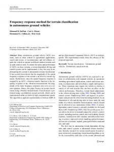
2. Terrain model Similar to work of Benes and Forsbach [20, 21] we constructed our terrain model as a layered representation. However, in our case we used two layers with independent records. Both layers are discrete m-by-n matrices, where m, n ∈ N. The first layer stores information about heights (height-field), while the other contains hardness data (hardness-field). All of our simulations are based on synthetic data. The height-field layers are generated with particle downfall algorithm [22]. For hardness-field synthesis, we used the modified Poisson Faulting method [23]. A sample of generated model layers is shown in Figure 1.
(a) height-field layer (rendered in Terragen)
(b) hardness-field layer
Figure 1. Sample of model layers.
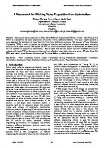
3. Erosion process Long term erosion processes are usually based on land flattening in downstream transportation of geological material through terrain areas. The classic modelling approach does not require the information about the soil susceptibility for erosion forces, like its internal chemical structure or density, and usually smoothens the terrains. The hardness layer adds valuable information to terrain model. In our simulations, we select two major phases in the erosion process. The first phase is a landslide where reduction of height-field is applied. The second phase is a land levelling
78
Korneliusz K. Warszawski, Sławomir S. Nikiel
Figure 2. Structure of erosion algorithm.
where we simulate downstream material transportation. The structure of erosion simulation algorithm is presented in Figure 2.
3.1. Landslide procedure In the landslide phase, we make height modifications of the terrain model with regard to the erosion force and underlying geological structure. The latter is generated in related hardness-field model. A sample of solely landslide procedure results is shown in Figure 3 and the initial model for that sample is presented in Figure 1. Let (D) be a hardness-field layer of terrain model. Let (F ) be an erosion force which affects the whole surface of the model, and where {F ∈ R | 0 ≤ F ≤ 1}. Let (i, j) be a pair of indexes, where i, j ∈ N. Let (di,j ) be a hardness data stored in a cell from the hardness-field layer (D), where {di,j ∈ R | 0 ≤ di,j ≤ 1} and let it be inversely proportional to the erosion force. Then the loss of height (∆h) can be calculated from the Equation 1.
∆h =
F , dij
0,
if di,j > 0 (1) otherwise
Let (H) be a height-field layer and let (hi,j ) be a record stored in the layer, where {hi,j ∈ R | min ≤ hi,j ≤ max | min 6= max}. Then the new value of the terrain structure cell (h0i,j ) will be modified by the loss of height (∆h) factor as is presented in Equation 2. In exception for cells which has no hardness defined in which case, the terrain surface is levelled to the ground level.
A proposition of erosion algorithm for terrain models with hardness layer
(a) after 50 steps
79
(b) after 100 steps
Figure 3. Sample results of landslide procedure (rendered in Terragen).
h0i,j =
hi,j − ∆h, if di,j > 0
0,
(2)
otherwise
3.2. Land levelling procedure In the second phase we simulate the downstream material transportation. Each record of the height-field layer after landslide phase is recalculated as an average value stored in that record and its neighbourhood. We assumed that the material can be transferred only in range of one cell. According to cell position, it can have three neighbours when cell is located in corner of height-field layer, or it can have five neighbours if it is located on layer border, or it can have eight neighbours in all other positions. A sample of solely land levelling procedure results is presented in Figure 4 and the initial model for that sample is shown in Figure 1. Let (h0i,j ) be the landslide height record stored in the cell of layer (H). Let (i, j) define indexes of that cell. Let (k) be the number of the cell neighbours, where {k ∈ N | k = 3, 5, 8}. Then new cell height record (h00i,j ) calculation can be constructed as in Equation 3.
(a) after 50 steps
(b) after 100 steps
Figure 4. Sample results of land levelling procedures (rendered in Terragen).
80
Korneliusz K. Warszawski, Sławomir S. Nikiel
Pi+1 h00i,j
=
p=i−1
Pj+1
q=j−1
h0i,j
(3)
k+1
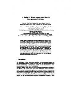
4. Results Above discussed partial erosion procedures combining height-field and hardness models gives results useful in virtual environments. The combination offer better visual simulation tools for erosion processes. Our experiments revealed that the impact of land levelling phase on the final model is definitely larger than of the solely landslide phase. To avoid rapid flattening of the landscape we choose to limit the number of levelling procedures in the simulation of the erosion process. We called this factor the levelling ratio and it has form of (1/x) which means that one land levelling procedure is executed after every x landslide phases. Sample results of levelling ratio influence for final model is shown in Figure 5 and the initial model for that sample is presented in Figure 1. The sample landscape presented in Figures 1, 3–5 was 300 × 300 resolution model with 4th class (λ) hardness layer [23] and erosion force value set to 1 × 10⁻³ .
(a) levelling ratio 1/1
(b) levelling ratio 1/5
(c) levelling ratio 1/10
(d) levelling ratio 1/25
Figure 5. Sample results of full erosion process after 100 steps (rendered in Terragen).
A proposition of erosion algorithm for terrain models with hardness layer
81
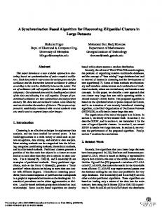
The average performance of the implemented prototype model was near real-time. The test experiment was executed on standard Intel Core i7-4771 CPU and was repeated 1000 times as a sequential implementation. Terrain layers were generated at each step. The erosion force was set to 1 × 10⁻⁴ and levelling ratio was set to 1 : 1. The hardness layer was the 5th class. For test groups we chose models resolution between 500 × 500 and 900 × 900 nodes. The performance diagrams for landslide and land levelling procedures is shown in Figure 6.
(a) landslide
(b) land levelling
Figure 6. Performance graphs.
5. Conclusions Application of terrain models with hardness layer in erosion introduces soil classes for landslide simulation process. As in natural terrains, there are areas which erode with different peace. The internal structure built from softer geological materials is washed out quicker than the sectors of terrain built from harder minerals. The landslide phase reflects the direct pressure of the erosion forces where land levelling phase reproduces movement of soil elements. The method performance shows almost linear nature of the algorithm. The medium resolution of model, can be successfully used in application running on standard workstation or home computers. The further research will be concentrated on adopting the method for voxel-based models and parallel implementation of the simulation algorithm. This could be potentially helpful in the studies on effect of erosion in three-dimensional models, i.e. caves, rock shelves or cliffs. Figures 7–10 presents additional examples of algorithm results.
Acknowledgements The author is a scholar within Sub-measure 8.2.2 Regional Innovation Strategies, Measure 8.2 Transfer of knowledge, Priority VIII Regional human resources for the economy Human Capital Operational Programme co-financed by European Social Fund and state budget.
82
Korneliusz K. Warszawski, Sławomir S. Nikiel
(a) initial model
(b) hardness layer
(c) after 15 steps
(d) after 30 steps
Figure 7. Model size 120 × 80 nodes, λ = 3, F = 1 × 10⁻³ , levelling ratio 1/7.
(a) initial model
(b) hardness layer
(c) after 15 steps
(d) after 30 steps
Figure 8. Model size 120 × 80 nodes, λ = 5, F = 1 × 10⁻² , levelling ratio 1/5.
(a) initial model
(b) hardness layer
(c) after 25 steps
(d) after 50 steps
Figure 9. Model size 800 × 800 nodes, λ = 5, F = 1.5 × 10⁻³ , levelling ratio 1/5.
(a) initial model
(b) hardness layer
(c) after 25 steps
(d) after 50 steps
Figure 10. Model size 320 × 240 nodes, λ = 7, F = 2.5 × 10⁻³ , levelling ratio 1/10.
A proposition of erosion algorithm for terrain models with hardness layer
83
References [1] Yokoya, N., Yamamoto, K., Funakubo, N.: Fractal-based analysis and interpolation of 3D natural surface shapes and their application to terrain modeling. Computer Vision, Graphics, and Image Processing, 46(3), p. 284–302, 1982. [2] Barnsley, M. F.: Fractals Everywhere. Academic Press, Boston, USA, 1993. [3] Crilly, A. J., Earnshaw, R. A., Jones, H.: Applications of Fractals and Chaos. Springer-Verlag, 1993. [4] Mandelbrot, B. B.: The fractal geometry of nature. H.W. Freeman and Co., San Francisco, USA, 2nd edition, 1982. ISBN 0-7167-1186-9. [5] Fournier, A., Fussell, D., Carpenter, L.: Computer rendering of stochastic models. Communications of the ACM, 25(6), pp. 371–384, 1982. ISSN 0001-0782. [6] Peitgen, H.-O., Saupe, D.: The Science of Fractal Images. Springer-Verlag, New York, USA, 1988. ISBN 0-387-96608-0. [7] Musgrave, F. K., Kolb, C. E., Mace, R. S.: The synthesis and rendering of eroded fractal terrains. In: 16th Annual Conference on Computer Graphics and Interactive Techniques (SIGGRAPH ’89), pp. 41–50. Boston, USA, 1989. ISBN 0-89791-312-4. [8] Dixon, A. R.: The Synthesis of Fractal Terrain and its Application to Flight and Space Simulation. Phd thesis, University of Hull, Hull, England, 1994. [9] Dixon, A. R., Kirby, G. H., Wills, D. M. P.: Artificial Planets with Fractal Feature Specification. The Visual Computer, 15(3), pp. 219–228, 1999. [10] Foster, N., Fedkiw, R.: Practical animation of liquids. In: 28th Annual Conference on Computer Graphics and Interactive Techniques (SIGGRAPH ’01), pp. 23–30. Los Angeles, USA, 2001. ISBN 1-58113-374-X. [11] Chae, D.-J., Park, J.-H.: An active model of water movement by activity-based method for simulation of the virtual environment. International Journal of Information Technology, 12(5), pp. 80–87, 2006. [12] Nagashima, K.: Computer generation of eroded valley and mountain terrains. The Visual Computer, 13, pp. 456–464, 1997. [13] Miller, G. S. P.: The definition and rendering of terrain maps. Computer Graphics, 20(4), pp. 39–48, 1986. [14] Teoh, S.: River and coastal action in automatic terrain generation. In: International Conference on Computer Graphics and Virtual Reality, pp. 3–9. Las Vegas, USA, 2008. [15] Reeves, W. T.: Particle Systems – A technique for modelling a class of fuzzy objects. In: 10th Annual Conference on Computer Graphics and Interactive Techniques (SIGGRAPH ’83), pp. 359–375. Detroit, USA, 1983. ISBN 0-89791-109-1. [16] Sims, K.: Particle animation and rendering using data parallel computation. In: 17th Annual Conference on Computer Graphics and Interactive Techniques (SIGGRAPH ’90), pp. 405–413. Dallas, USA, 1990. ISBN 0-89791-344-2. [17] Benes, B., Roa, T.: Simulating Desert Scenery. In: 12th International Conferences in Central Europe on Computer Graphics, Visualization and Computer Vision (WSCG ’04), pp. 17–22. Plzen–Bory, Czech Republic, 2004. ISBN 80-903100-5-2. [18] Benes, B.: Real-Time Erosion Using Shallow Water Simulation. In: 4th Workshop in Virtual Reality Interactions and Physical Simulation (VRIPHYS ’07), pp. 43–50. Dublin, Ireland, 2007. [19] Kristof, P., Benes, B., Krivanek, J., Stava, O.: Hydraulic Erosion Using Smoothed Particle Hydrodynamics. Computer Graphics Forum, 28(2), pp. 219–228, 2009. [20] Benes, B., Forsbach, R.: Layered data representation for visual simulation of terrain erosion. In: 17th Spring Conference on Computer Graphics (SCCG ’01), pp. 80–85. Budmerice, Slovakia, 2001. ISBN 0-7695-1215-1. [21] Benes, B., Forsbach, R.: Visual Simulation of Hydraulic Erosion. In: 10th International
84
Korneliusz K. Warszawski, Sławomir S. Nikiel
Conferences in Central Europe on Computer Graphics, Visualization and Computer Vision (WSCG ’02), pp. 79–86. Plzen–Bory, Czech Republic, 2002. ISSN 1213-6972. [22] Warszawski, K.: Ground from smoke: Using particle systems for Terrain Modeling in C#. Game Developer Magazine, 16(3), pp. 15–21, 2009. [23] Warszawski, K., Nikiel, S., Zawadzki, T.: Hardness data synthesis for height-field based landscape models. In: 18th Surface models for geosciences (GIS ’12), pp. 275–284. Ostrava, Czech Republic, 2012. ISBN 978-80-248-2667-7.