AbstractâIn this research, the feasibility of a real-time active matching circuit for biomedical WPT applications is discussed. Also, the genetic-algorithm based ...
A Real-time Electrically Controlled Active Matching Circuit utilizing Genetic Algorithms for Biomedical WPT Applications Jo Bito, Soyeon Jeong and Manos M. Tentzeris School of Electrical and Computer Engineering Georgia Institute of Technology Atlanta, GA, USA
Abstract—In this research, the feasibility of a real-time active matching circuit for biomedical WPT applications is discussed. Also, the genetic-algorithm based matching circuit design method utilizing discrete circuit components is introduced and the practicality of active matching circuits for WPT is verified with preliminary measurement results featuring a maximum of 3 dB of improvement in transmission coefficient for a range of spanning a coil to coil distance of 10 to 12 cm, which was achieved by inserting the active matching circuit. Index Terms—Real-time systems, Impedance matching, Power transmission
I. I NTRODUCTION Wireless power transmission (WPT) technology is one of the most highly demanded technologies to realize truly cableless/batteryless mobile devices and wirelessly connected electronics, that are required for practical implementations of Internet of Things (IoT) topologies. In addition to these applications, the medical field is one of the most important application areas of this technology. For hygienic purposes, a typical characteristic of microwaves, that they can transfer power to sealed devices, is a huge advantage. Also, WPT could have a significant impact in health and biomonitoring applications, virtually eliminating the need for painful and infection-prone surgical procedures, which are currently necessary for periodical battery replacement, by charging wirelessly in-vivo implanted electronics. In this research, the feasibility of a real-time matching circuit for magnetic resonance coupling WPT systems for biomedical applications is introduced. In this system, a discrete value matching circuit with a combination of lumped circuit elements and PIN diode switches, which are electrically controlled by a microcontroller, is adopted to decrease the mismatch between the signal generator and the transmitting coil, which has a self-resonance frequency of 13.56 MHz. II. S YSTEM OVERVIEW A two-frequency split, called horn effect, is usually associated with the fundamental operation of the magnetic resonance wireless power transmission in configurations with very small separation distances between transmitter and receiver coils [1]. This can be a major issue for WPT applications on moving platforms, such as the human body, typically pushing the values of resonance frequency outside the allowable frequency bands or drastically deteriorating the coupling efficiency. In c 978-1-4673-7447-7/15/$31.00 2015 IEEE
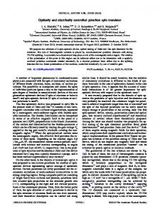
Fig. 1: Block diagram of a dual transmitting coil wireless power transmission system with real-time matching circuits.
order to compensate for the effect of human body part movements (e.g. breathing and turning), a real-time active matching circuit can be inserted between the signal source and the transmitter coil. Also, it has been discussed that the use of multiple transmitter coils can possibly enhance the focused available power in the human body within the SAR limitations of maximum transmitted power [2]. The overview of the proposed dual-delivery transmitting coil wireless power transmission system with real-time matching circuits is depicted in Figure 1. III. R EAL - TIME M ATCHING C IRCUIT The proposed reconfigurable real-time matching circuit system is composed of an optimized family of lumped component matching elements and PIN diodes. The PIN diodes are controlled by a microcontroller to choose the best configuration for the matching circuit by changing the combination of on/off state for each PIN diode. In this work, the PIN diode SMP1340 from Skyworks is adopted in order to achieve a fast matching circuit operation. A. Matching Circuit Design using a Genetic Algorithm In an ideal case, a dynamically changing matching circuit can be composed of a π network which has variable component values. However, in reality, it is quite challenging to change the impedance values arbitrarily within a wide dynamic range in RF circuits. There are couple of different ways to realize arbitrary different impedance values by utilizing electrically controlled variable circuit components.
However, in the research presented in this paper,a discrete value impedance matching circuit with PIN diode switches is adopted because of its inherent broad range of operating frequencies, fast switching speed and robustness. For proofof-concept demonstration purposes, the topology used in this research is composed of 6 series inductors and 6 parallel capacitors. Each stage consists of an L-type two-element configuration, that are grounded through a PIN diode, which acts as the switching element. Since every switch provides 2 states, 6 switches can provide a total of 64 states. In this effort, genetic algorithms were utilized in order to determine the optimal lumped component values for typical WPT matching applications out of the available standard discrete component values. Genetic algorithms (GA) are heuristic search methods, which have been widely used to solve electromagnetic optimization problems [3]. Here, the Global Optimization Toolbox of MATLAB was utilized to solve the impedance matching problem. The procedure to evaluate the performance of the circuit design is described in [4]. The return loss and the transducer gain which play an important role for the matching over a large part of the Smith chart are used respectively as the RL and GT optimization parameters of the genetic algorithm. These can be expressed as a function of the two-port Sparameters, and the load and the source reflection coefficients [5]. The transducer gain can account for dissipative losses in the circuit as well as mismatches. The return losses indicate the quality of matching to the load impedance [6]. S12 S21 ΓL ) 1 − S22 ΓL
(dB)
(1)
|S21 |2 (1 − |ΓL |2 ) ) |1 − S22 ΓL |2
(dB)
(2)
RL = −20log(S11 + GT = −10log(
From the literature, it is possible to achieve the maximum Smith chart coverage up to 70 % under the conditions for RL and GT which guarantee the improvement of matching, RL < -10dB and GT > -2dB, by utilizing arbitrary circuit component values [4]. The proposed method can effectively realize the Smith chart coverage of 50 to 60 % satisfying the same criteria by modifying the combination of discrete set of circuit components. Each component value in the set is chosen from commercially available lumped component values. For both inductors and capacitors, 28 consecutive commonly used circuit values, which cover 103 optimal range for the operation frequency of 13.56 MHz were considered. By limiting the number of components in the set of circuit components in such a way, the simulation time was significantly reduced. B. Real-time Maximum Operation Point Search One of the easiest and most accurate ways to assess the quality of the matching and operate the system at the maximum power transfer point is to monitor the S-parameters values and change the state combination of the matching circuit to the highest value of the transmission coefficient which minimizes the reflection coefficient. However, in reality, introducing a
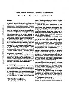
-Designate limitation -All design variables to integer
Generate Population
Evaluate Fitness Function For each chromosome For certain frequency (13.56MHz) For each Tunable Matching Circuit State For each load impedance Calculate Coverage of Smith Chart (%impedances)
Mutation
Crossover
Selection of parents
Maximum number of iteration? No Yes Select the best combination
Build the prototype with selected componets combination
Fig. 2: Flow chart of the GA optimization.
network analyzer into the system is not a practical choice in terms of cost and flexibility. Also, there is no physical connection between the receiver device and the matching quality control unit, thus making it difficult to directly measure the received power. In order to overcome this problem, a maximum power transfer assessment topology based on the reflected power measured by utilizing a circulator and a detector diode was designed as shown in Figure 3. In this system, reflected power goes only through the detector diode because of the circulator, and the output DC voltage from the diode is measured by utilizing an ADC in microcontroller. With this method, the system does not require any RF measurement equipments, which usually add more cost to the system. If the output voltage of the detector diode is at the minimum value, it can be assumed that the power transfer is maximized. Based on this assumption, the real-time matching algorithm on the matching circuit was implemented as shown in Figure 4. The major limitation for the fast real-time matching circuit operation is switching speed of PIN diode which is in the range of hundreds of ns [7] [8]. However, in our system, there are only 64 states in the matching circuit. Therefore, the required time for maximum operation point search can easily be less than 1 ms which is sufficiently small on the scale of the human movement times. IV. T RANSMITTER AND R ECEIVER C OIL D ESIGN In this effort, an open type helical coil which has a self resonance frequency of 13.56 MHz was designed on CST STUDIO SUITE 2014. In order to reduce the simulation time, the integral solver was adopted. The simulation results yielded the following coil dimensions; the radius of the coil is 50 mm, the diameter of the copper wire is 1 mm, the gap between each wire is 0.2 mm, and the number of turns is 26, to achieve the operation frequency of 13.56 MHz. Based on the simulation results, transmitter and receiver coils were fabricated with 1 mm diameter copper wire. Laser cut acrylic boards were used as the supporter. The picture of a fabricated coil, and
Fig. 3: Block diagram of matching circuit quality assessment system utilizing a circulator and a detector diode. -Initialize the MCU -Wait until the MCU is stabilized
Swithch diodes to the next combination
Once the time is over, initialize the diode combination & reset the stored output voltage data
Measure the output voltage wiht ADC multiple times & store the sampled data
Take the average of samples & store the averaged data as represented value for the diode combination
Maximum output voltage search & use the best combination for fixed length of time
Yes
Are all the combinations sampled?
No
Fig. 4: Flow chart of the real-time matching procedure with a microcontroller.
simulated and measured S11 values are shown in Figure 5 (a) and (b), respectively. The higher loss in the measurement is assumed to be associated with greater radiation loss because of the fabrication error. V. C HARACTERIZATION OF M ATCHING C IRCUIT In this section, measured S-parameters of the Tx and Rx coil WPT topology at different center to center coil separation values, in the range of 10 to 15 cm, were used to verify
5cm
Meas Sim
S11 (dB)
−0.5 −1 −1.5 −2
Copper Wire (a)
−2.5 12
13 14 Frequency (MHz)
VI. C ONCLUSION The feasibility of a real-time active matching circuit for biomedical WPT applications was discussed. A possible realtime matching algorithm and an approach for matching circuit quality assessment were suggested. Also, a design approach utilizing the genetic algorithm for the realization of the optimal discrete-elements based matching circuit was introduced and the practicality of active matching circuits for WPT was proven for a coil to coil distances of 10 cm to 12 cm. As a result, a 3 dB improvement in transmission coefficient, a doubling the transferred power, was achieved by inserting the proposed real-time active matching circuit.
0
Acrylic Board
the operation of the designed matching circuit. During the GA simulations, based of the available lumped component values, the center of the Smith chart was targeted, offering 50 -60 % coverage at 13.56 MHz. However, the inductive component value of the fifth cell was changed from 27 nH to 560 nH in order to optimize the operation for the measured coil S-parameters. In Figure 6, the schematic of the GAdesigned matching circuit and the picture of the matching circuit prototype are depicted. The circuit was fabricated on a 1.5 mm thick substrate, RO4003C, which features a dielectric constant of 3.38, provided by Rogers Cooperation. The measured and simulated reflection coefficient values for the designed matching circuit are shown in Figure 7. For the measurement, bias circuits, each composed of a series inductor and a parallel capacitor, were connected to each pin of the matching circuit prototype to isolate the bias circuit from the matching circuit. The DC control voltages were provided by Arduino Uno microcontroller board. The simulation and measurement results agree quite well. After the data acquisition of the matching circuit impedance values, the best combination of diode on/off states, which maximizes the transmission coefficient between Tx and Rx coils, was chosen on the simulation for each coil separation distance, based on the measured matching circuit and coil S-parameter values. During the simulation, the receiver coil is terminated with a 50 Ω load. The simulated reflection and transmission coefficient for various coil-to-coil distances ranging between 10 cm and 15 cm with and without matching circuit are shown in Figure 8 (a) and (b), respectively. From the figures, it can be easily observed that the reflection coefficient decreases at any distance by inserting the proposed matching circuit, and that the transmission coefficient improves at short distance. However, at large distance, the transmission coefficient slightly decreases because of the insertion loss associated with the matching circuit, as the energy is dissipated in the lumped components and PIN diode, and leakage to the bias circuit. In the worst case scenario, about 18 % of the energy is possibly lost in this way.
15
(b)
Fig. 5: (a) Wireless power transfer coil prototype. (b) Measured and simulated S11 of the wireless power transfer coil.
VII. ACKNOWLEDGMENT The work of J. Bito, S. Jeong and M. M. Tentzeris was supported by National Science Foundation (NSF) and Defense Threat Reduction Agency (DTRA).
Transmission Coil
Signal Source
Reflection coefficient (dB)
(a)
0
−15
−30
−45 9
10
Without matching circuit With matching circuit 11 12 13 14 15 16 Distance (cm)
Bias Pins
(b)
Fig. 6: (a) Modified tunable matching circuit design schematic designed using a GA. (b) Prototype of tunable matching circuit with modified components value.
Transmission Coefficient (dB)
(a)
Inductor Capacitor PIN Diode Via Hole
0
−5
−10
−15 9
Without matching circuit With matching circuit 10 11 12 13 14 Distance (cm)
15
16
(b)
Fig. 8: (a) Reflection coefficient with and without matching circuit. (b) Transmission coefficient with and without matching circuit.
Fig. 7: Measured and simulated reflection coefficient values utilizing the proposed real-time matching circuit.
R EFERENCES [1] T. Imura, H. Okabe, and Y. Hori, “Basic experimental study on helical antennas of wireless power transfer for electric vehicles by using magnetic resonant couplings,” in Vehicle Power and Propulsion Conference, 2009. VPPC ’09. IEEE, Sept 2009, pp. 936–940. [2] J. Bito, B. S. Cook, and M. M. Tentzeris, “A multi-coil wireless power transfer system utilizing dynamic matching for in-vivo and biomedical applications,” in Microwave Conference (APMC), 2014 Asia-Pacific, Nov 2014, pp. 680–682. [3] J. Johnson and V. Rahmat-Samii, “Genetic algorithms in engineering electromagnetics,” Antennas and Propagation Magazine, IEEE, vol. 39, no. 4, pp. 7–21, Aug 1997. [4] C. Sanchez-Perez, J. de Mingo, P. Carro, and P. Garcia-Ducar, “Design and applications of a 300-800 mhz tunable matching network,” Emerging and Selected Topics in Circuits and Systems, IEEE Journal on, vol. 3, no. 4, pp. 531–540, Dec 2013. [5] C. Sanchez-Perez, J. de Mingo, P. Garcia-Ducar, P. Carro, and A. Valdovinos, “Figures of merit and performance measurements for rf and microwave tunable matching networks,” in Microwave Integrated Circuits Conference (EuMIC), 2011 European, Oct 2011, pp. 402–405. [6] F. Casini, R. Gatti, V. Perrone, and R. Sorrentino, “A new approach to the analysis and synthesis of lossy reconfigurable matching networks,”
in Microwave Conference, 2009. EuMC 2009. European, Sept 2009, pp. 1235–1238. [7] Application Note: Design with PIN diodes, Skyworks Solutions, Inc., Oct 2012. [8] Data Sheet: SMP1340 Series: Fast Switching Speed, Low Capacitance, Plastic Packaged PIN Diodes, Skyworks Solutions, Inc., June 2012.