Magnetically Activated Stereoscopic Vision System for Laparoendoscopic Single Site Surgery Massimiliano Simi Student, IEEE, Michele Silvestri, Carmela Cavallotti Student, IEEE, Monica Vatteroni Member, IEEE, Pietro Valdastri, Member, IEEE, Arianna Menciassi, Member, IEEE, Paolo Dario, Fellow, IEEE
Abstract - In this paper, the authors present an innovative vision platform for laparoendoscopic single site surgery based on a wired and magnetically activated 5-degrees-of-freedom robot with stereovision. The stereoscopic vision module, developed using two off-the-shelf cameras and a Light Emitting Diodes lighting system, is mounted on the robot tip. An autostereoscopic screen is adopted to display the surgical scenario as an alternative to three-dimensional helmets or polarizing glasses. A rough position of the stereocamera can be determined along the abdominal wall by dragging the robot with a set of external permanent magnets. Once the camera is set in the desired position, the external permanent magnets provide fixation, while the internal mechanism allows fine tilt adjustment. Considering the deformable round shape of the insufflated abdomen wall and in order to replicate the precise roll motion usually provided by the endoscopist’s hands, this prototype embeds an actuated mechanism that adjusts the stereocamera horizon and thus prevents any visual discomfort. Finally, the platform was preliminarily tested in-vivo in a laparoendoscopic single-site scenario, demonstrating its advantages for eliminating potential conflicts with the operative tools and enabling the introduction of an additional instrument through the same access port used for stereoscopic vision. Index Terms— Stereo vision, Robotic camera, Medical robotics, Image sensors.
I. INTRODUCTION
O
N-GOING medical research efforts aim to reduce morbidity and are moving towards scarless surgery. Representing the latest advance in minimally invasive surgery, LaparoEndoscopic Single-Site (LESS) surgery allows significant improvement in this direction. The access technique for LESS involves the use either of access ports or of a series of 5 mm trocars side by side in the same incision, which is approximately 25-30 mm large and typically placed at the patient’s umbilicus [1]. The technical feasibility of transumbilical-LESS has been clearly demonstrated for a wide range of surgical procedures using different access ports already available on the market [2, 3]. Despite promising to concretely improve traditional minimally invasive surgery, LESS still presents technical challenges This work was supported in part by the European Commission within the framework of the ARAKNES European Project EU/IST-2008-224565. The authors are with The BioRobotics Institute, Scuola Superiore Sant’Anna, 56127 Pisa, Italy. Pietro Valdastri is with the Storm Lab, Vanderbilt University, Nashville, TN, USA. (e-mail:
[email protected];
[email protected],
[email protected],
[email protected];
[email protected];
[email protected];
[email protected]).
that are far from being solved [4]. One of these challenges is limited triangulation and retraction of tissue due to the confinement of optics and working instruments to a single axis [5]. This severely hampers the field of view of the surgical scenario and the manoeuvrability of the instruments. In addition, outside the patient’s abdomen, the conflict between the endoscopist manoeuvring the camera, and the surgeon controlling the assistive and operative instruments, reduces the available workspace and may lead to unexpected movements during surgery. A series of articulating instruments are currently available on the market, specifically designed to accomplish a certain degree of triangulation [6]. The vision system commonly used in LESS surgery is a rigid extra-long endoscope coupled with an extracorporeal video-camera [7]. The restricted motion of this kind of endoscope through the access port results in a limited endoscopic view. Today, there is only one commercial endoscope purposely designed for LESS, i.e. the Endoeye, developed by Olympus. The Endoeye is a chip-on-the-tip two-dimensional (2D) 30° endoscope with 5 mm diameter and a flexible tip providing 100° field of view [8]. The Da Vinci robotic system (Intuitive Surgical Inc., USA) has also been proposed for LESS surgery (or Robotic-LESS) [9]. Besides providing easier articulation, motion scaling and tremor filtration [10], the robot’s main advantage is a fine three-dimensional (3D) vision which is the key to restoring depth cue, normally lacking since the introduction of laparoscopy. The drawbacks of the robotic system, however, regard the viewing console which completely isolates the surgeon from the surrounding environment and the significant external and internal encumbrance of the entire system, not specifically designed for LESS. Hence, further developments in robotic platform designs and visualization systems are needed. A possible solution for addressing LESS open issues is represented by softlytethered miniaturized camera robots. These robotic cameras are not constrained by the entry incision, allowing the surgeon to place additional instruments safely and appropriately. Moreover, these systems provide additional camera angles that increase surgical visualization and improve orientation. The systems are positioned intraabdominally and stabilized by suturing [10], by needle locking [12] or by external permanent magnets placed on the abdominal skin [13], in order to guarantee a large field of view and to leave the access port free for a different instrument. A number of magnetic anchoring and guidance system (MAGS) cameras are presented in [14-16]. In [17]
IEEE/ASME Transactions on Mechatronics, 2013, Vol.18, n.3, pp.1140-1151
and [18], camera robots are developed with two active internal Degrees of Freedom (DOFs) and magnetic anchoring. A stereoscopic robotic camera (2 DOFs: pan and tilt) is described in [19, 20]. However, this device does not include a lighting system nor an anchoring system, and it is sutured on the abdominal wall during experimental validation. Our goal is to improve the present technology by proposing an innovative magnetically activated stereocamera robot [21]. The design specifications for a novel stereoscopic vision platform based on a wired and magnetically-activated robot are reported in Section II. The system overview and the details of the imaging system are reported in Sections III and IV, respectively, while Section V illustrates the robot design in terms of DOFs and activation method. Experimental results are reported in Section VI. II. DESIGN SPECIFICATIONS The system requirements related to the development of a LESS camera robot are determined by medical considerations, physical constraints and technical limitations. Imaging system. Image quality in diagnosis and surgery always seems to be insufficient; VGA resolution, however, could be well suited for a first assessment of robotic prototypes [22]. Obviously, 3D vision is preferred over 2D vision; furthermore, in order to accomplish the typical operative tasks in LESS procedures and to avoid stereoscopic distortion, the vision system must guarantee correct 3D viewing from 50 mm up to 150 mm in scene depth. Efficient and uniform illumination is also fundamental to guarantee sharp images without 3D distortions. Illumination must exceed the minimum luminous intensity required for the cameras to be in proper working conditions in every spatial location without saturation. Finally, the visualization of the operative images must allow comfortable viewing (i.e. without glasses, helmets or immersive console) to the highest number of operators and trainees. Robotic system. The robot should have the highest number of DOFs in the smallest size to facilitate surgical mini-invasive procedures. In addition, it must fit the surgical single incision. Thus, considering the outer diameter of the umbilical ports ranging between 25 mm and 30 mm [23], a diameter of 30 mm can be set as maximum size for the robotic camera. Furthermore, the robot must avoid contact between the stereocamera and organs during surgical procedures. Considering that the operative field varies from person to person, since similar robotic camera prototypes [11, 17] have been used in extensive clinical testing, their upper length limit of 110 mm can be considered adequate. As regards the DOFs, the pan and tilt are necessary for pointing towards the different areas of the abdomen, whereas the roll is fundamental for restoring the right perception of the horizon, thus facilitating the procedure and avoiding any visual discomfort. In order to replicate the precise motion usually provided by the endoscopist’s hands, a > 5 rpm speed and < 1° resolution are considered sufficient for each
active DOF. Finally, possible sterilization of the entire device must be considered. III. SYSTEM OVERVIEW Based on the above specifications, we designed a robotic 3D vision system as schematically represented in Fig. 1. It incorporates a stereovision module at the tip, based on 2 cameras with 2 separate optical channels and a lighting system. A thin (2 mm in diameter) flexible wired connection to the external unit allows real time video signal transmission, system control and powering. Furthermore, it leaves the trocar free for the insertion of another tool, allowing effective retrieval from the abdomen in case of failure. A dedicated hardware is used for video data management. The signals from the cameras are sent to a frame synchronizing device that adapts the format to a 3D display. Despite new shutter glasses TVs are cheap and userfriendly, an autostereoscopic monitor was adopted because it avoids isolating the observer from the surrounding environment and allows more than one observer to watch the surgical scene in 3D at the same time without glasses. These features can improve the surgeon’s performances if applied in the operating room [24]. On the other hand, autostereoscopic technology is still in its early stages and provides different solutions for achieving 3D perception, each with specific strengths and weaknesses. Such a scattered scenario is the reason why previous assessment studies on autostereoscopic technologies present conflicting results [25-27]. In the present work, an autostereoscopic display was adopted in order to provide an open console for the operator, without the need for any additional component, such as polarized glasses. This approach seems to be in line with the current trend of consumer electronics where large efforts have been spent over the past years in autostereoscopic technology [28-30].
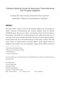
Fig. 1. Schematic view of the robotic system. The solid arrows represent the DOFs of the robot: 3 passive (Pan and Shift in two directions) and 2 active (Tilt and Roll). The dashed arrows represent all the forces and torques acting on the pivoting point of the internal permanent magnet (IPM) and considered in the model. The external permanent magnets (EPMs transmit the passive DOFs.)
With regard to the system motion, three rough external DOFs, which are manually activated, correctly position and anchor the robot inside the abdomen, whereas other two
IEEE/ASME Transactions on Mechatronics, 2013, Vol.18, n.3, pp.1140-1151
motorized DOFs (Tilt and Roll) inside the robotic stereocamera accurately steer and orient the surgeon’s point of view. The tilt DOF is actuated by the Magnetic Internal Mechanism (MIM) [31, 32] and consists of a motor connected to an internal permanent magnet (IPM) by a set of gears. The device, immersed in an external magnetic field generated by external permanent magnets (EPMs), tends to maintain precise alignment defined by IPM polarization. When the motor is activated, the entire device rotates with it, while the IPM remains oriented according to the external field. Thanks to this operation principle, the MIM enables the device to tilt according to the surrounding tissue, without moving the EPMs. The second active DOF precisely adjusts the horizon of the stereo vision system. As regards horizon adjusting, it is worth mentioning that, while software image rotation is sufficient in case of a single camera, a hardware solution is required for a stereoscopic system in order to avoid reducing image resolution. The head of the robot with 2 parallel cameras is connected to the motor by means of a set of cylindrical gears and can rotate with a span of ±90° thus guaranteeing horizon adjustment for all possible deviations. The two embedded motors are then controlled by a Personal Computer (PC) or by a specially developed pushbutton interface. IV. IMAGING SYSTEM DESIGN A. System Architecture The development of a stereoscopic imaging system includes two main parts: a device that acquires two 2D images of the scene and a system that separates these images so that each observer’s eye receives only one of them [33]. Among the several strategies available for acquiring stereoscopic image stream [34, 7, 35], the simplest method was adopted in this work, i.e. two separate optical channels were implemented by two adjacent cameras. The maximum size section for a square camera was set at 10 mm × 10 mm, so as not to exceed the maximum diameter of the LESS umbilical incision (25 mm). In addition, in order to balance the loss of brightness due to the dual-channel optics, a wellsuited lighting system was required, as better detailed further on. After a benchmark analysis, VGA CMOS color imagers, 8 mm × 8 mm × 9 mm in size, with pin-hole lens (Misumi Electronics Corp., Taiwan) were chosen as the best trade-off between image quality, low power consumption, embedded image processing tools and low cost. These cameras have a field of view of about 60° in horizontal and 52° in vertical. The camera output is in NTSC (National Television System Committee) format, which can provide 400 TV lines in resolution, with an image transfer rate of 60 frames-persecond (fps). As display unit, a 19’’ (1280×1024) autostereoscopic monitor (Pavonine Korea Inc., Korea) was used. This device employs the parallax barrier technology for 3D visualization. The parallax barrier is an electro-optic panel with vertical, regularly spaced slits attached to the surface of a Liquid Crystal Display (LCD). The slits are used to obscure parts of the two images coming from the cameras, thus spreading
two separate 2D images ahead of the monitor [36] (Fig. 2). Consequently, the difference in the received right and left images, given by the horizontal separation of the cameras, is perceived by the observer’s eyes without the need for helmets or glasses. The user’s brain then fuses this difference, called disparity (measured in degrees or mm), thus producing the perception of depth. This screen has an optimal viewing distance of 80 cm, with a tolerance, related to the observer’s individual eye separation, of about ±10 cm, and guarantees a viewing angle of about 110° with a correct stereoscopic zone, called sweetspot, each about 2° [37].
Fig. 2. The sweet-spots of the adopted autostereoscopic display, based on the parallax barrier technology.
B. System Dimensioning Imaging system dimensioning was based on the selected display and camera features and on the system specifications, in order to calculate the optimal distance between the cameras centers by means of geometrical models [38, 39]. Furthermore, the best configuration for the illumination system was theoretically studied by implementing a numerical model. Two different camera set-ups are usually adopted in the state of the art [33]: the parallel and the toed-in set-ups. The first has a larger range of depth in which the disparity complies with the physiological limits, and also prevents peculiar stereoscopic distortions. The toed-in configuration instead has better 3D rendering performance for a fixed target, where the background is less significant. The parallel configuration was chosen in the present work because the target does not have a fixed and pre-known position in the scene, and the background information is very useful for the surgeon. For this configuration, system dimensioning was carried out using the following equations [38, 39]: 1 1 Dmin = M ⋅ t ⋅ f ⋅ − d 0 d min D = M ⋅ t ⋅ f ⋅ 1 − 1 d max 0 d max
(1)
where Dmin and Dmax are, respectively, the minimum and the maximum allowed disparity values, M is the value of frame magnification, dmin and dmax are the minimum and the maximum required scene depth values and d0 is the zerodisparity-depth, f the focal length and t the distance between
IEEE/ASME Transactions on Mechatronics, 2013, Vol.18, n.3, pp.1140-1151
the two camera centers. In the case of Misumi cameras, focal length is 3.1 mm, frame magnification is 93.75 (given by the ratio between sensor width and autostereoscopic monitor width). As defined in Section II, scene depth range is 50÷150 mm. The disparity limits are obtained from the following relations: e 2 ⋅ arctan +µ 2⋅ Z −e Dmin = 2 ⋅ Z ⋅ tan 2 e 2 ⋅ arctan −µ 2⋅ Z −e Dmax = 2 ⋅ Z ⋅ tan 2
5).Therefore, the 8 LED configuration, equally distributed above and below the camera, was selected.
(2)
where Z is the optimal viewing distance from the autostereoscopic monitor (80 cm), e is the typical human eye separation (65 mm) and µ = ±1,5° is the physiological disparity limit [33]. Solving Eq. 1 using these disparity limits, the distance obtained between the two camera centers is 8.7 mm, thus producing a maximum lateral size of both cameras of 8.7 mm. This constraint agrees with the chosen cameras, whose width is 8 mm. Finally, the proposed system also required appropriate illumination, with light distribution in the scene as uniform as possible, in order to avoid artifacts in the 3D viewing. As light source, white Light Emitting Diodes (LEDs) (Nichia Corp., Tokushima, Japan) were used, because of their high efficiency (1000 mcd of emitted power) and compact size (2 mm × 1.2 mm × 1.3 mm) [40]. Unfortunately, no models or guidelines for optimal distribution of the light sources for medical applications can be found in literature. Therefore an approximate mathematical model for light propagation was adopted. The implemented propagation law, based on the Lambert-Beer rule [41] and on the emission features of the LEDs, allows calculation of the luminous intensity associated to each light source for every spatial location in the workspace by applying the superposition effect. This model neglects scattering effects and reflection phenomena in order to hold down the computational load. Four different LED configurations, shown in Fig. 3, were tested: one with 4 LEDs (configuration 1), two with 6 LEDs using two different geometrical arrangements (configurations 2 and 3) and one with 8 LEDs (configuration 4). A higher number of LEDs was not considered because of space constraints and in order to prevent sensor saturation. As illumination uniformity parameter, the percentage of the stereoscopic Field of View (FOV) having a Coefficient of Variation (CV) less than 5% was evaluated for each configuration [41]. Moreover, the tested lighting configurations were requested to overcome minimum luminous intensity, equal to 0.2 lux, required for the cameras to operate in proper working conditions in every spatial location. Results from simulations are reported in Fig. 4. The 8 LED configuration showed better performance in terms of illumination uniformity and guaranteed a minimum luminous intensity within the stereoscopic FOV much larger than the minimum value requested by the cameras (Fig.
Fig. 3. The four LED configurations tested by the theoretical model. LEDs are shown inserted in the case (22 mm in diameter) of the electronic illumination system, that has a central hole for hosting the cameras.
Fig. 4. Comparison between the LED configurations concerning the uniformity parameter, i.e. the percentage of the stereoscopic FOV having a CV less than 5%. As the stereoscopic FOV size varies with depth, the uniformity parameter is also displayed along the scene depth.
The 8 LEDs and necessary drivers were mounted on a Printed Circuit Board (PCB), designed to surround the cameras at the same level of the sensors, thus avoiding unwanted reflections from the glass used to hermetically seal the device. Light source temperature ranged from 37 °C to 40 °C, comparable with standard laparoscopic fiberoptic sources. The whole imaging system was finally 23 mm in diameter and 9 mm in depth (corresponding to the camera thickness), and weighed 3.8 g. V. ROBOTIC SYSTEM DESIGN All robot parts were selected and designed considering stereovision module size, umbilical port diameter and the other mechanical requirements described above. In order to fabricate the chassis of the prototype with a stereolithographic rapid prototyping technique (3D Printer Invision Si2), a total diameter of 25 mm was considered, which represents the limit guaranteeing solidity of the shell (minimum wall thickness of 1 mm) and internal stability of all mechanical components.
IEEE/ASME Transactions on Mechatronics, 2013, Vol.18, n.3, pp.1140-1151
was fixed at 3 cm from the bottom of the robot in a dedicated rear tank, which allows the robot to be coupled with two external permanent magnets (EPMs), thus stabilizing anchorage and providing the external pan and x-y translation. The EPMs must be selected once the entire robot system has been designed and assembled in order to satisfy the technical requirements related to magnetic anchoring, external pan motion and magnetic tilt.
Fig. 6. Three-dimensional design of the robotic stereocamera. The main embedded components of the device and the parts of the chassis are shown.
Fig. 5. a) A schematic representation of the model geometry showing how the stereoscopic FOV was extrapolated and the origin of the coordinates. The theoretical lighting intensity distributions within the stereoscopic FOV at b) 50 mm in depth, c) 100 mm in depth. These distributions were obtained using LED configuration 4. The x- and y-axis are the coordinates, measured in mm, implemented in the model. The zaxis is the light intensity measured in lux.
A. IPM selection As first step, the IPM features were defined to maximize magnetic attraction force and torque in the internal diameter (23 mm) of the robot, also considering the mechanism configuration as represented in Fig.6. A diametrically magnetized commercially available NdFeB N52 permanent magnet (KJ Magnetics, Jamison, US) was selected. The permanent magnet has a ring shape, measures 12.7 mm in diameter and 12.7 mm in thickness, and has an axial hole of 3.2 mm. Another ring magnet, with the same IPM features,
B. Motor Selection and Design of Mechanisms In order to satisfy the speed and resolution requirements of the two internal DOFs (tilt and roll), two Maxon EC6 DC brushless motors [42], with 221:1 planetary gearhead and inductive encoder were selected as the best commercially available trade-off between resolution ( Tmim Tmot > Tmim
Fig. 7. The assembled prototype magnetically anchored to the abdomen simulator.
C. Fabrication and Assembly Both pinion and main gears were fabricated using a 5-axis micro-CNC machining center (HSPC, KERN GmbH, Germany) as in [45], whereas the steel worm gear and the bronze helical gear were custom designed by the authors and fabricated by an external workshop. The gears were modified by Sink and Micro Wire Electro Discharge Machining (EDM) (Micro Sink, Sarix, Switzerland, and AP 200L, Sodick, Japan, respectively) to provide proper couplings between connecting parts. In particular, the worm gear was cut at one end in order to obtain a rectangular groove, while a T-shaped hole was made in the helical gear to enable proper connection with the brass shaft as in [46]. The motor shafts were machined by Micro Wire EDM and fitted into the hole of dedicated brass bushes, whereas a brass holed plate was used to link the main gear to the robot head. All gear shafts were assembled on ball bearings, apart from the worm gear that was mounted on custom-made bushes in synthetic ruby with buffing surface to minimize the friction force and overall dimensions. The plastic chassis is composed of 5 different parts (head, body, bottom, plug and tank) that can be easily fitted together. The head, where the cameras are fixed, can rotate along the cylindrical axis with a span of ±90°. The body, where the head and the bottom parts can be fixed, has two 6 mm-diameter holes for the motor, two rectangular grooves for the motor connectors and a slot for the IPM. Additionally, a dedicated half-moon hole is obtained along
(3) (4) (5)
where Fm and Fw are the EPMs-IPM magnetic attraction force and the device weight force, respectively. Tm is the magnetic torque exerted by the EPMs on the IPM, Tmim is the maximum torque exerted by the weight of the device on the IPM pivot and Tmot is the total torque that the brushless motor transmits to the IPM by means of the internal mechanism (see Fig. 1). Due to the very slippery properties of the abdomen wall, the friction between tissue and camera robot was neglected at this stage. The camera device weighs 57 g, therefore, a magnetic attraction force larger than 560 mN (Fw) is required to completely lift the robot at a distance of 30 mm. Given mass and arrangement of all device components, its center of mass (26 mm from the IPM pivot) was derived and Tmim was analytically calculated as 14.76 mNm. Finally, as previously derived, Tmot is 445 mNm. Since the EPMs must be easily handled by the doctor, and on the basis also of our simple model, two off-the-shelf (KJ Magnetics, Jamison U.S.) cubic (25.5 mm x 25.5 mm x 25.5 mm) magnets (NdFeB, N52) were selected as best compromise between external magnetic field maximization and size. FEM analysis of these permanents magnets was performed to predict magnetic forces (Fm) and torques (Tm) (see Fig. 8). The magnetic attraction force between EPMs and IPM (Fm) is 2.8 N, while the magnetic torque (Tm) goes from 0 to 45 mNm for an IPM rotation angle ranging from 0° to 90° as represented in Fig. 9. The Tmim torque was reached for an IPM rotation angle of about 20°. Still based on the simulation results, the maximum magnetic flux density that surrounded the two brushless motors may be evaluated as being equal to 0.1 T, thus satisfying the negligible effect of the magnetic field on the actuator features. Finally, the two EPMs were embedded into a plastic case to improve handling. In case of a thicker abdominal wall, larger EPMs can be used to cope with the increased distance.
IEEE/ASME Transactions on Mechatronics, 2013, Vol.18, n.3, pp.1140-1151
Fig. 8. FEM simulation of interaction between the magnets. The selected mesh consisted in about 1,350,000 elements, with a minimum quality ratio of 0.35.
Fig. 9. Plot of the Tm on the IPM as function of the rotation angle. The circle highlights when the Tm is equal to Tmim.
VI. EXPERIMENTAL RESULTS A. System functionality characterization After assembling the robot, a number of bench tests were carried out to evaluate system performance and reliability. Firstly, anchoring, pan and translation stability between EPMs and the camera system were verified by simply moving the robot by hand in a Plexiglas simulator abdomen for LESS, having a simulated wall thickness of 30 mm. Then, the active DOFs were evaluated by controlling the span motion with the PC interface. As regards the tilt DOF, a 0 – 90° magnet rotation range was set. A span of 70° is about 1.5 seconds long, confirming the speed theoretically derived during the design phase; after about 70°, MIM is no longer effective. During the tilt motion, the link between the rear magnet and the robot hampered robot rotation, thus limiting the robot tilt range. A redefined design of the bodytank link, e.g using a spring element, would allow this problem to be solved. Thanks to the PC interface, the embedded motors may be controlled step by step; consequently, the highest MIM resolution obtained was lower than 0.01°. Active roll DOF features were evaluated, still using the PC control interface. No problems occurred for the ±90° range that was performed in about 0.5 seconds, thus confirming the horizon adjustment high speed, whereas the highest resolution obtained for the step motor control was lower than 0.01° in this case also. In order to evaluate the results obtained with the approximated model for lighting distribution, an
experimental test was carried out. The system was placed in the laparoscopic simulator at increasing distances (i.e. from 50 mm to 150 mm, with a 10 mm pitch) from a monochromatic flat target, acquiring a stereo-pair for each distance. The obtained images were processed in order to evaluate the percentage of the FOV having a CV less than 5%, which is the same parameter used in the model. The experimental distributions obtained confirm theoretical predictions (Fig.10). Since the lowest intensity value obtained is far from zero, the developed illumination system shows its effectiveness in overcoming the minimum intensity value required to make the cameras work correctly. However, as shown in Fig. 11, illumination uniformity is less than in the model results. This may be due to scattering and reflective phenomena that, although neglected in the model, increase lighting distribution slopes and so worsen illumination uniformity [41]. As the differences between theoretical and experimental FOV percentage have a maximum value below 0.06% and an average value of 0.045%, this work validates the implemented model. Moreover, during the tests, our lighting system qualitatively guaranteed images with satisfactory brightness and without any illumination distribution discontinuities. B. Assessment of the system in medical tasks on bench To obtain a quantitative evaluation of the prototype’s operative performance, a comparative study between a standard 2D laparoscope and our 3D imaging robot was also carried out. Both systems were mounted in the plexiglas LESS simulator; 16 surgeons were asked to perform two basic tasks in two different abdomen quadrants, and execution time was recorded. The first task performed in the right lower quadrant consisted in inserting 10 rings into 10 needles using a LESS pincer (pick-and-place task), while the second task, conducted in the left upper quadrant, consisted in performing a single suture on a synthetic skin (suturing task). At the beginning of each task the robot was located near the insertion port. It was then roughly moved on the target area by using the EPMs, and the exact point of view was reached thanks to the active MIM and roll adjustment. When the traditional laparoscope was used, the task was always started by positioning the laparoscope perpendicular to the skin. After manual pointing by the surgeon, it was then held in the same position by an assistant. In order to avoid learning bias, the order of the imaging system was randomized. Average execution times were evaluated using the Analysis of Variance (ANOVA) test, taking differences as statistically significant when p ≤ 0.05 [48]. As summarized in Table II, average execution time was about 20 seconds lower in 3D viewing conditions for both tasks. Moreover, these large differences were statistically significant when using the ANOVA test. This demonstrated that the developed stereoscopic imaging system significantly improves speed and efficiency in both low (pick and place) and high (suture) complexity tasks, thanks to a better relative distance and motion control.
IEEE/ASME Transactions on Mechatronics, 2013, Vol.18, n.3, pp.1140-1151
a)
b) Fig. 10. Experimental lighting distribution obtained at a) 50 mm in depth, and b) 100 mm in depth. The z-axis is the pixel intensity of the acquired image of the target. As the processing unit embedded in the camera performs while balancing operation, the resulting dynamic range of the intensity vs. depth is normalized. The x-axis and the y-axis are the image coordinates, measured in pixels.
After the quantitative test, doctors were asked to answer a questionnaire in order to assess the quality of the stereo images provided by our prototype. Almost 80% of them greatly appreciated the 3D imaging provided by our platform. On the other hand, some of them found it stressful to properly fuse the stereo-images provided by the autostereoscopic display. It is worth mentioning that results related to the 3D display are valid only for the specific parallax barrier technology. Indeed, different technological solutions to achieve autostereoscopy could result in different performances in terms of user-friendliness and effectiveness [51]. However, all participants qualitatively confirmed the stereoscopic depth range from 50 mm to 150 mm and appreciated the brightness of the images. As to the robotic system, the surgeons’ qualitative assessments of the device were good in terms of reliability, motion resolution and simple control. Being able to reach appropriate and nonpreplanned points of view of different areas inside the abdominal cavity was considered to be the main advantage of the robotic prototype. The high number of DOFs (active and passive) of the system, which always ensure good mobility inside the abdomen, was a very appreciated quality. In particular, the use of manual operation for rough positioning and of robotic control for fine adjustment greatly enhanced camera pointing precision. Finally, the roll DOF was considered fundamental in restoring the correct horizon position after robot motion, thus facilitating understanding of the scenario and, therefore, of the entire surgical procedure. TABLE II Average Execution time 3D
Average Execution time 2D
p-value
Pick and Place
128 s
144 s
0.0011
Suturing
105 s
124 s
0.0202
Table II. Results obtained during the quantitative comparison test on performance time. The data represent average execution time in both viewing conditions and ANOVA relevance.
C. Assessment of the system in in-vivo conditions
Fig. 11. Comparison between theoretical and experimental illumination uniformity. The evaluated parameter is still the FOV percentage, varying along the scene depth, having a CV less than 5%. The blue line represents the theoretical result obtained using the LED configuration. The red dotted line represents the experimental results obtained by processing the acquired images of the target.
This helps to perform tasks more rapidly under 3D viewing conditions, regardless of their complexity and of the doctor’s individual surgical experiences [49,50].
A preliminary in vivo test was performed on a 35 kg female pig to evaluate the capabilities of the entire robotic platform in a real LESS surgical scenario. The aim was to visualize and recognize the main organs of the abdominal cavity, placed in different quadrants, from different viewpoints. Ethylene oxide sterilization of the device was performed on the entire device before the in vivo test. The experiment was conducted in an authorized laboratory with the assistance and collaboration of a specially trained medical team, in compliance with all ethical requirements and regulatory issues related to animal experiments. After intravenous sedation of the animal, a
IEEE/ASME Transactions on Mechatronics, 2013, Vol.18, n.3, pp.1140-1151
LESS procedure was performed using a SILSTM port (Covidien, Norwalk, CT, USA). The following procedure was executed for the insertion, use and removal of the stereocamera robot: 1. The abdomen was incised at the navel. 2. The stereoscopic robotic camera was inserted in the abdomen. 3. The robot was magnetically anchored. 4. The flexible cable crossed the hole of the umbilical port from the side of the electronic connector (D < 10 mm). 5. The umbilical port was inserted in the pig’s abdomen. 6. The abdomen was inflated. 7. The stereocamera robot was moved and actuated to focus on stomach, liver, spleen, intestine, colon, diaphragm, and gall bladder. Whenever a change in the abdominal quadrant was required, the device was repositioned by magnetic dragging. 8. At the end of the procedure, the EPMs were removed. 9. The single site port was retrieved with the robot through the abdominal wall incision. The entire insertion procedure described above (steps 1-6) was easily performed. The prototype was correctly anchored to the abdomen wall. Pneumoperitoneum was established through the valve. Then the robot was moved within the abdominal cavity. The robot successfully enabled a visual survey of the entire cavity (Fig. 12).
Fig. 12. An additional traditional laparoscope was inserted during the in vivo test to follow and evaluate the motion of the robot within the abdominal cavity. In the figure, the robot (on the right), is observing a section of the abdominal cavity (intestine and liver).
All the organs were clearly identifiable. The illumination provided by the LEDs was found suitable for LESS by the surgeon and the 3D perception on the autostereoscopic display allowed the entire surgical team to easily follow the procedure. During the inspection procedure, an endoscopist was able to operate both the EPMs and the button interface by following commands from the surgeon. The anchoring and rough motion of the robot with the EPMs was very stable, and the endoscopist found the other active DOFs very simple to control (step 7). Once the abdominal cavity visual inspection was completed, the removal procedure (steps 8-9) was successfully carried out without any problem. At the end of the in vivo test both the surgeon’s and endoscopist’s qualitative assessments of the device were very positive. As demonstrated also during the bench tests, the 3 passive DOFs always allow the desired abdominal area to be reached, whereas the 2 active DOFs (tilt and roll) ensure
precise points of view and guarantee adequate speed, high resolution and sufficient span angle. VII. CONCLUSIONS An innovative vision platform for LESS, based on a magnetically activated stereoscopic wired robot, has been proposed in this paper. The presented softly-tethered robot embeds a stereoscopic vision module, a LEDs lighting system, magnetic fixation to the abdomen wall and 5 DOFs (2 active and 3 passive) for stereocamera steering. A working prototype was designed and fabricated (25 mm in diameter, 95 mm in length and 57 g in weight). The robotic endoscope can be inserted through a 25 mm incision and magnetically fixed on the abdominal wall. As in [13-18], a rough position can be obtained along the abdominal wall by dragging the robot by hand motion of the EPMs, thus allowing the endoscope to easily reach areas placed in different abdominal quadrants and so providing completely new points of view. Accordingly with other prototypes [13-18], the novel robotic endoscope has the potential to restore triangulation for the surgeon and to reduce both instrument collision and procedure invasiveness. Furthermore, the present device can provide a larger viewing volume than a traditional laparoscope which is restricted by the fulcrum point of insertion. Another main advantage offered by the robot is that the space in the access port is only partly taken up by a thin cable (2 mm), thus leaving space for the access of additional instrumentation that could be useful during complex surgical procedures. In comparison with [13-18], once the stereocamera is positioned, fine tilt and roll orientation can be obtained by exploiting the two active embedded mechanisms. Unlike [17-19], the 0-70° tilt angle of view is provided by the active MIM and may be compared to the span obtained with a traditional endoscope during LESS surgical procedures. Additionally, since the tilting motion is not manual as in [1316], but motorized, image stability and motion resolution are greatly enhanced. Again compared to standard laparoscopes, the proposed system has a robotized rotational DOF around its long axis, thus allowing the image to be rotated. We restored this feature, which is lacking in all other robotic cameras [12-20], with a dedicated gear mechanism. Consequently, the roll active embedded motion always guarantees correct horizon adjustment with a span of ±90° (Fig. 13). The speed and resolution of the two motorized DOFs is sufficient to ensure quick adjustment and reliable motion. Considering [20], the embedded illumination system and the possible magnetic adjustment along the abdomen wall, combined with additionally and highly precise internal DOFs, represent the main improvements brought about. Regarding the qualitative-assessment tests carried out, physicians positively evaluated the stereoscopic effect, the brightness of the images and the friendliness of the 5 DOFs steering mechanism. Compared to standard LESS imaging systems, they also appreciated the field of view provided and the possibility to precisely tilt and rotate the imaging point of view, thus balancing the lower FOV compared to standard endoscopes [7]. Qualitatively, the imagery was sufficient to conclude the in vivo abdominal cavity visual inspection. As
IEEE/ASME Transactions on Mechatronics, 2013, Vol.18, n.3, pp.1140-1151
demonstrated by the comparison test, the stereoscopic effect showed good results in terms of binocular cues and content handiness. 3D image stream allowed better performances as regards efficiency and execution speed, compared to conventional 2D vision in both low and high complexity tasks. The autostereoscopic display allowed all participants to perceive the third dimension, consequently, the surgeon was not isolated from the surgical scenario and the assistants were always aware of the status of the procedure. Depth perception and relative motion perception guaranteed by binocular cues were appreciated. 80% of participants was in fact mostly made up of persons who found it effortless and natural to enter into the third dimension provided by the autostereoscopic screen. The development of newgeneration autostereoscopic displays may further improve this condition. Future developments intend improving camera resolution in order to enhance image quality. Moreover, a new processing unit will need to be developed to improve noise filtering and image sharpness. Finally, a future smaller prototype will be considered in order to introduce the entire robot through a traditional surgical trocar (φ = 12 mm), thus expanding the impact on standard laparoscopic procedures.
[2]
[3]
[4]
[5]
[6]
[7] [8] [9]
[10]
[11]
[12]
[13]
[14]
[15]
[16]
[17] Fig. 13. Stereoscopic robotic point of view during visual inspection in the abdominal cavity. The left and right sides represent the two images from the stereocamera. a) Images directly taken by the cameras when the robot is placed on the abdominal wall. b) Images taken after horizon adjustment thanks to the active roll mechanism.
ACKNOWLEDGMENTS The authors would like to thank N. Funaro for manufacturing the prototypes. They would also like to thank G. Sardi for his technical support on the FEM simulation and G. Petroni for his technical support on PC and button control interface.
[18]
[19]
[20]
[21]
REFERENCES [1]
C. R. Tracy, J. D. Raman, J. A. Cadeddu, A. Rane, “Laparoendoscopic single-site surgery in urology: where have we been and where are we heading?” in Nature Clinical Practice Urology vol. 5, pp. 561-568, 2008.
[22]
W. Brunner, J. Schirnhofer, N. Waldstein-Wartenberg, R. Frass, K. Pimpl and H. Weiss, “New: Single-incision transumbilical laparoscopic surgery” in European Surgery, vol 41, pp. 98-103, 2009. M. Neto, A. Ramos, J. Campos, “Single port laparoscopic access surgery” in Techniques in Gastrointestinal Endoscopy, vol. 11, pp. 8493, 2009. Peter Weibl. "Current Limitations and Perspectives in Single Port Surgery: Pros and Cons Laparo-Endoscopic Single-Site Surgery (LESS) for Renal Surgery", Diagnostic and Therapeutic Endoscopy, Vol. 2010, ID 759431, 3 pages, 2010. I. S. Gill, A. P. Advincula, M. Aron, J. Caddedu, D. Canes, P. G. Curcillo, M. M. Desai, J. C. Evanko, T. Falcone and V. Fazio, et al., “Consensus statement of the consortium for laparoendoscopic singlesite surgery” in Surgical Endoscopy, vol. 24, pp. 762-768, 2010. S. S. Kommu, A. Rané, “Devices for laparo-endoscopic single-site surgery in urology” in Expert Review of Medical Devices vol.6, pp. 95-103, 2009. http://www.karlstorz.com/, last access 11/10/2010 http://www.olympuskeymed.com/, last access 9/10/2010. J. H. Kaouk, R. K. Goel,G. P. Haber, S. Crouzet, R. J. Stein, “Robotic single-port transumbilical surgery in humans: initial report” in BJU international, vol. 103, pp. 366 - 369, 2008. R. J. Stein, W. M. White, R. K. Goel, B. H. Irwin, G. P. Haber, J. H. Kaouk, “Robotic Laparoendoscopic Single-Site Surgery Using GelPort as the Access Platform” in European Urology, vol. 57,pp. 132-137,2010. T. Hu, P. K. Allen, N. J. Hogle and D. L. Fowler, “Insertable Surgical Imaging Device with Pan, Tilt, Zoom, and Lighting” in The International Journal of Robotics, vol. 28, pp. 1373-1386, 2009. T. Kawahara, T. Takaki, I. Ishii, M.Okajima, “ Development of a Broad-View Camera System for Minimally Invasive Surgery”, presented at the 2010 IEEE/RSJ International Conference on Intelligent Robots and Systems, October 18-22, 2010, Taipei, Taiwan. I. S. Zeltser, R. Bergs, R. Fernandez, L. Baker, R. Eberhart, J. A. Cadeddu, “Single trocar laparoscopic nephrectomy using magnetic anchoring and guidance system in the porcine model” in The Journal of Urology, vol. 178, pp. 288-291, 2007. J. A. Cadeddu, R. Fernandez, M. Desai, R. Bergs, C. Tracy, S. J. Tang, P. Rao, M. Desai, D. Scott, “Novel magnetically guided intraabdominal camera to facilitate laparoendoscopic single-site surgery: initial human experience” in Surgical Endoscopy, vol. 23, pp. 18941899, 2009. M. Fakhry, B. Gallagher, F. Bello, G. B. Hanna, “Visual exposure using single-handed magnet-driven intra-abdominal wireless camera in minimal access surgery Is better than 30° endoscope”, in Surgical Endoscopy, vol. 23, pp. 539-543, 2009. P. Swain, R. Austin, K. Bally, R. Trusty, “ Development and testing of a tethered, independent camera for notes and sigle-site laparoscopic procedures” in Surgical Endoscopy, vol. 24, pp.:2013-2021, 2010. A. C. Lehman, K. A. Berg, J. Dumpert, N. A. Wood, A. Q. Visty, M. E. Rentschler, S. R. Platt, S. M. Farritor, D. Oleynikov, “Surgery with cooperative robots” in Computer Aided Surgery, vol. 13, pp. 95-105, 2008. S. R. Platt, J. A. Hawks, and M. E. Rentschler, “Vision and Task Assistance Using Modular Wireless In Vivo Surgical Robots” in IEEE Transactions on Biomedical Engineering, vol. 56, pp. 1700-1710, 2009. T. Hu, P. K. Allen, T. Nadkarni, N. J. Hogle, D. L. Fowler, "Insertable stereoscopic 3D surgical imaging device with pan and tilt," presented at the 2nd IEEE RAS & EMBS International Conference on in Biomedical Robotics and Biomechatronics , pp.311-316, Oct. 19-22, 2008, Scottsdale, AZ. D. L. Fowler, T. H.T. Nadkarni, P. K. Allen, N. J. Hogle, “Initial trial of a stereoscopic, insertable, remotely controlled camera for minimal access surgery” in Surgical Endoscopy, vol. 24, pp. 9–15, 2010. M. Silvestri, M.Simi, C. Cavallotti, M. Vatteroni, P. Valdastri, A. Menciassi, P. Dario. “Design of a magnetically stereoscopic system for single port laparoscopy”, presented at the 3rd Hamlyn Symposium on Medical Robotics, pp. 63-64, May 25, 2010, London, UK. M. Vatteroni, D. Covi, C. Cavallotti, L. Clemente, P. Valdastri, A. Menciassi, P. Dario, A. Sartori, “Smart optical CMOS sensor for endoluminal application” Sensors and Actuators A: Physical, 2010, Vol. 162, No. 2, pp. 297-303.
IEEE/ASME Transactions on Mechatronics, 2013, Vol.18, n.3, pp.1140-1151
[23] J.R. Romanelli, D. B. Earle, “Single-port laparoscopic surgery: an overview” in Surgical Endoscopy, vol. 23, pp. 1419–1427, 2009 [24] C.M. Grossmann, “A new AS-display as part of the MIRO lightweight robot for surgical applications” in Proceedings of the SPIE – the International Society for Optical Engineering, vol. 7524, 2010. [25] M. Silvestri, M. Simi, C. Cavallotti, M. Vatteroni, V. Ferrari, C. Freschi, P. Valdastri, A. Menciassi, P. Dario, “Autostereoscopic Three-dimensional viewer evaluation through comparison with conventional interfaces in laparoscopic surgery” in Surgical Innovation, vol. 18, pp. 223-230, 2011. [26] UDA Mueller-Richter, A Limberger, P Weber, W Spitzer, M Schilling, “Comparison between three-dimensional presentation of endoscopic procedures with polarization glasses and an autostereoscopic display” in Surgical Endoscopy, vol. 17, pp. 502504, 2003. [27] ZY Alpaslan, SC Yeh, AA Rizzo, AA Sawchuk, “Quantitative Comparison of Interaction with Shutter Glasses and Autostereoscopic Displays” in Proceedings of the SPIE: The International Society for Optical Engineering, vol. 5664, pp. 616-625, 2005. [28] Harris M, “3D Without Four Eyes” in IEEE Spectrum, vol. 47, pp. 5056, 2010. [29] Http://www.microsoft.com/showcase/ last access 11/10/2010 [30] https://www.sle.sharp.co.uk 25/10/2010 [31] P. Valdastri, C. Quaglia, E. Buselli, A. Arezzo, N. Di Lorenzo, M. Morino, A. Menciassi, P. Dario, “A magnetic internal mechanism for precise orientation of the camera in wireless endoluminal applications” in Endoscopy, vol. 42, pp.481-486, 2010. [32] M. Simi, G. Ciuti, S. Tognarelli, P. Valdastri, A. Menciassi, P. Dario, “Magnetic link design for a robotic laparoscopic camera” in Journal of Applied Physics, 2010. (107), 09B302, pp.1-3. [33] M. Ferrè, R. Aracil, M. Sanchez-Uran, “Stereoscopic Human Interfaces” in Robotics & Automation Magazine, IEEE, vol. 15, pp. 50–57, 2008. [34] J. H. Palep; “Robotic assisted minimally invasive surgery” in Journal of Minimal Access Surgery, vol. 5, pp. 1-7, 2009. [35] C. Y. Chen, T.T. Yang, W. S. Sun; “Optics system design applying a micro-prism array of a single lens stereo pair” in Optics Express, vol. 16, pp. 15495-15505, 2008. [36] L. Hill, A. Jacobs, “3-D liquid crystal displays and their applications” in Proceedings of the IEEE; vol. 94, pp. 575-589, 2006. [37] http://www.miracube3d.com last access 25/10/2010 [38] A. Woods, T. Docherty, R. Koch, “Image Distortions in Stereoscopic Video Systems” in Proceedings of the SPIE, Stereoscopic Displays and Applications IV, vol. 1915, pp. 36-48, 1993, San Jose, CA. [39] N. Holliman “Mapping Perceived Depth to Regions of Interest in Stereoscopic Images” in Proceedings of SPIE, Stereoscopic Displays and Virtual Reality Systems XI; vol. 5291, pp. 1-12, 2004. [40] http://www.nichia.com. last access 11/10/2010 [41] C.P. Poole; “The Physics Handbook”; Wiley-Interscience Pubblications pp. 188-202. [42] http://www.maxon.net/, last access 30/10/2010. [43] M. Simi, P. Valdastri, C. Quaglia, A. Menciassi, P. Dario “Design, Fabrication and Testing of a Capsule with Hybrid Locomotion for Gastrointestinal Tract Exploration” in IEEE/ASME Trans. Mechatronics, vol. 15, pp. 170-180, 2010. [44] http://www.roymech.co.uk/Useful_Tables/Drive/Gears.html, last access 30/10/2010. [45] P.Valdastri, R. J. Webster III, C. Quaglia, M. Quirini, A. Menciassi, P. Dario, “A New Mechanism for Meso-Scale Legged Locomotion in Compliant Tubular Environments”, IEEE Transactions on Robotics, 2009, Vol. 25, No. 5, pp. 1047-1057. [46] M. Quirini, A. Menciassi, S. Scapellato, C. Stefanini, and P. Dario, “Design and fabrication of a motor legged capsule for the active exploration of the gastrointestinal tract,” IEEE/ASME Trans. Mechatronics, vol. 13, no. 2, pp. 169–179, Apr. 2008 [47] C. Song, A. Alijani, T. Frank, G. B. Hanna, A. Cuschieri, “Mechanical properties of the human abdominal wall measured in vivo during insufflation for laparoscopic surgery” in Surgical Endoscopy, vol. 20, 2006, pp. 987-990. [48] D. Freedman, R. Pisani; “Statistics”; Norton; 1991. [49] S. H. Kong, B.M. Oh, H. Yoon, H. S. Ahn, H. J. Lee, S. G. Chung, N. Shiraishi, S. Kitano, H. K. Yang; “Comparison of two- and threedimensional camera systems in laparoscopic performance: a novel 3D
system with one camera” in Surgical Endoscopy, vol. 24, pp. 1132– 1143, 2010. [50] V. Falk, J. Grunenfelder, J. I. Fann, T. A. Burdon, “Influence of threedimensional vision on surgical telemanipulator performance” in Surgical Endoscopy, vol. 15, pp. 1282-1288, 2001. [51] M. Barkowsky, P. Le Callet, “The influence of autostereoscopic 3D displays on subsequent task performance” in Stereoscopic Displays and Applications XXI, vol. 1, 2010, San José.
Massimiliano Simi received a Master’s degree in biomedical engineering from the University of Pisa, Pisa, Italy, in April 2009. He is currently working toward a Ph.D. degree in biorobotics at The BioRobotics Institute, Scuola Superiore Sant’Anna, Pisa. He has been with the CRIM Laboratory as Research Assistant since June 2008. His current research interests include medical robotics and biomechatronics.
Michele Silvestri received a Master’s degree in biomedical engineering from the University of Pisa, Pisa, Italy, in June 2010. He is currently working toward a Ph.D. degree in biorobotics at The BioRobotics Institute, Scuola Superiore Sant’Anna, Pisa. His current research interests include biomechatronics and medical imaging.
Carmela Cavallotti received a Degree in Biomedical Engineering (with Honours) from the Campus Bio-Medico University in Rome in December 2007. She is currently a PhD student in biobiorobotics at The BioRobotics Institute of the Scuola Superiore Sant’Anna in Pisa. Her main research interests are in the fields of vision systems for biomedical applications.
Monica Vatteroni was born in La Spezia, Italy, in 1975. She received an M.S. degree in electrical engineering from the University of Pisa (Italy) in 2001 and a Ph.D. degree in Physics from the University of Trento (Italy), in 2008. Presently, she works for the Scuola Superiore Sant’Anna in Pisa (Italy) as post doctoral fellow, where she is responsible for the research and development of image sensors and vision systems.
Pietro Valdastri (M’05) received a Master’s (Hons.) degree in electronic engineering from the University of Pisa, Pisa, Italy, in 2002, and a Ph.D. degree in bioengineering from the Scuola Superiore Sant’Anna. He is now assistant professor at Vanderbilt University and director of the Storm Lab.
Arianna Menciassi (M’00) received a Master’s degree in physics from the University of Pisa, Pisa, Italy, in 1995, and a Ph.D. degree in Biomedical Engineering from the Scuola Superiore Sant’Anna, Pisa, in 1999. She is currently an Associate Professor of Biomedical Robotics at the Scuola Superiore Sant’Anna. She serves as Editorial Board on the IEEE/ASME Trans. of Mechatronics.
IEEE/ASME Transactions on Mechatronics, 2013, Vol.18, n.3, pp.1140-1151
Paolo Dario (M’99–SM’01–F’03) received a Master’s degree in mechanical engineering from the University of Pisa, Pisa, Italy, in 1977. He is currently a Professor of biomedical robotics at the Scuola Superiore Sant’Anna, Pisa, where he supervises a team of about 150 young researchers. He has authored or coauthored more than 200 ISI journal papers, many international patents, and several book chapters on medical robotics.
IEEE/ASME Transactions on Mechatronics, 2013, Vol.18, n.3, pp.1140-1151