The shadow map technology is a process by which shadows are added to 3D computer graphics. As the shadows can be treated as the blind spots of the remote.
A REALTIME METHOD FOR EVALUATE AERIAL REMOTE SENSING TASK Lei Feng, Chaoliang Wang, Bo Zhu Academy of Opto-Electronics, Chinese Academy of Sciences Beijing, China the blind spot area, and this really costs lots of time and money. So, here we provide a method to evaluate the aerial remote sensing task to avoid the blind spot problem, and as we use the three dimensional rendering technology, the method is a real time one. 2. METHODOLOGY
ABSTRACT As aerial remote sensing becoming a more and more important way for obtaining high resolution data, an effective method for evaluate the remote sensing task should be provided. The shadow map technology is a process by which shadows are added to 3D computer graphics. As the shadows can be treated as the blind spots of the remote sensors, so the shadow map technology was integrated to the evaluation method. It can show the blind spots of the planned task immediately to the user and is meaningful for aerial remote sensing. People can adjust the planned task according to the evaluated result to avoid wasting time and money.
2.1 Aerial Remote Sensing Task Data The aerial remote sensing task data we used in this paper is produced by the software we develop in our other project. The content contains the flying track, the taking sensor and the positions where to open and close the sensor. The flying track is a series of geographic coordinate points which has longitude (x), latitude (y) and elevation (z). The taking sensor tells the sensor parameters for calculate the view shed, for example the view angle and tilt angle. The positions where to open and close the sensor are also composed by the longitude (x), latitude (y) and elevation (z).
Index Terms— Viewshed Analysis, Spatial Analysis, Shadow Map, Aerial Remote Sensing 1. INTRODUCTION Aerial remote sensing is an important and efficient way for acquiring high resolution data, and becomes more and more popular recent years[1]. The first step of aerial remote sensing is to make a plan of the task which contains the flying track, the taking sensor and the positions where to open and close the sensor in order to satisfy the remote sensing requirement. Originally, people made an aerial remote sensing task plan manually, and this really takes a lot of time and could not ensure the precision of the task. As the computer technology developing, people develop some software which makes the things much better, like the ImageStation Mission Planning (IMSP) developed by Carl Zeiss and Intergraphy company, and CCNS from IGI company, Tracker system from Track’Air company and so on[2,3]. As these software are commercial ones, the users do not the internal algorithm, so lots of people developed their own system for their projects about the aerial remote sensing. But until now, most of the systems are concentrated on the degree of side overlap and forward overlap which is emphasized by the aerial photography and do not care about the ground surface situation. But when the flying track is over mountains and the sensor are working with large tilt angle, the blind spot of task will be easy to happen. Sometimes you must re-fly to get the remote sensing data for
978-1-4799-1114-1/13/$31.00 ©2013 IEEE
540
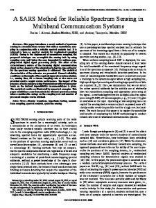
2.2 Shadow Mapping Technology Shadow mapping is a process by which shadows are added to 3D computer graphics. This concept was introduced by Lance Williams in 1978, in a paper entitled "Casting curved shadows on curved surfaces"[4]. In this method, shadows are created by testing whether a pixel is visible from the light source, by comparing it to a z-buffer or depth image of the light source's view, stored in the form of a texture[5]. The basic principle for create a shadow map is that if you looked out from a source of light, all of the objects you can see would appear in light. Anything behind those objects, however, would be in shadow. So, there are two steps for rendering the scene: first, the light's view is rendered, storing the depth of every surface it sees (the shadow map); next, the regular scene is rendered comparing the depth of every point drawn (as if it were being seen by the light, rather than the eye) to this depth map. The Figure 1 from Internet illustrates the basic algorithm of the shadow map. 2.3 Aerial Remote Sensing Task Evaluation As we describe the principle for create a shadow map, first we should look out from a source of light, if we change the
IGARSS 2013
light source to a camera or an aerial remote sensing sensor, all the shadows caused by terrain are the blind spots of the sensor where could not been obtained remote sensing data. So we could evaluate the aerial remote sensing task in this way, and show the blind spots in real time in 3D environment.
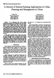
Figure 2 The Result of the Evaluation Method 4. CONCLUSION A real time method for evaluate aerial remote sensing task was provided in this paper, the method can show the blind spots of the planned task immediately to the user. It is meaningful for aerial remote sensing. People can adjust the planned task according to the evaluated result to avoid wasting time and money. But there is still some spaces for improve the method as the shadow mapping method is still developing for the precision and the efficiency. And the spatial resolution of the terrain is an important factor for the precision of the evaluation result.
Figure 1 An Overview of the Shadow Map Algorithm To make this happens, there are several steps we should do: • Construct a sensor model according to the sensor parameters; • Get the attitude of the sensor according to the aerial remote sensing task plan; • Make a 3D camera on behalf of the sensor; • Render the 3D scene to a depth buffer at the camera view; • Re-render the 3D scene for the user view and compute the blind spots using the shadow map method.
REFERENCES [1] Y. Duan, L. Yan, and Y. Xiang, "Design and experiment of UAV remote sensing optical targets," Electronics, Communications and Control (ICECC), 2011 International Conference on , vol., no., pp.202-205, 9-1, 2011.9. [2] THE TRACKER Aerial Photography System INFORMATION FOLDER [M/CD]. 2002-04-29. [3] Leica ADS80 Documentation [M/CD]. 2010-02-25. [5] L. Williams, “Casting curved shadows on curved surfaces”, Proceedings of the 5th annual conference on Computer graphics and interactive techniques, ACM: pp. 270-274, 1978.8 [5] http://en.wikipedia.org/wiki/Shadow_mapping.
3. RESULT For test effect of the method provided by this paper, we developed a simple demo. We use a small terrain area from ShaHe Beijing, China, and a simple flying track. But we change the view angle of the sensor all the time, and as you can see it could show the blind spot in real time which is colored by black. The bottom left the Figure 2 is the depth map calculated for the current position and current view angle.
541