Hindawi Publishing Corporation International Journal of Aerospace Engineering Volume 2015, Article ID 431824, 11 pages http://dx.doi.org/10.1155/2015/431824
Research Article A Reconstruction Algorithm for Blade Surface Based on Less Measured Points Jia Liu, Ji Zhao, Xu Yang, Jiming Liu, Xingtian Qu, and Xin Wang College of Mechanical Science and Engineering, Nanling Campus, Jilin University, Changchun 130025, China Correspondence should be addressed to Xu Yang;
[email protected] Received 5 July 2015; Revised 14 October 2015; Accepted 19 October 2015 Academic Editor: Roger L. Davis Copyright © 2015 Jia Liu et al. This is an open access article distributed under the Creative Commons Attribution License, which permits unrestricted use, distribution, and reproduction in any medium, provided the original work is properly cited. A reconstruction algorithm for blade surface from less measured points of section curves is given based on B-spline surface interpolation. The less measured points are divided into different segments by the key geometric points and throat points which are defined according to design concepts. The segmentations are performed by different fitting algorithms with consideration of curvature continuity as their boundary condition to avoid flow disturbance. Finally, a high-quality reconstruction surface model is obtained by using the B-spline curve meshes constructed by paired points. The advantage of this algorithm is the simplicity and effectivity reconstruction of blade surface to ensure the aerodynamic performance. Moreover, the obtained paired points can be regarded as measured points to measure and reconstruct the blade surface directly. Experimental results show that the reconstruction blade surface is suitable for precisely representing blade, evaluating machining accuracy, and analyzing machining allowance.
1. Introduction Blades with free-form surface are widely used in aviation industry. Generally, the blade cannot be finished in once machining, and the measurement and reconstruction are needed repeatedly until the deviation between reconstruction model of semifinished blades and the designed ones meets the requirements. Besides that, the blade design and damaged blade repairing also need the reconstructed model from the existing ones. Therefore, the reverse technology about blade surface has received extensive attention recently in both research and industrial areas [1–3]. For reconstruction of blades, the measured points are usually obtained from the coordinate measuring machine and then transformed into a 3D model by using surface reconstruction algorithms for further work [4]. The algorithms [5] for surface reconstruction proposed in literature can be divided into two classes: triangular mesh algorithms and parametric surface algorithms. In general, the purpose of triangular mesh method is to transform the measured points data to a mesh surface. First, a triangular mesh is generated as a seed. And then by an optimized
algorithm for regional growth a smooth surface passes through the optimized mesh which is reconstructed [6]. The triangulation method for measured points has a low efficiency in the calculation process [7]. And the triangular mesh surface is imprecise and easily influenced by noise for reverse engineering [8–11]. However, parametric surface can be more efficient and accurate to represent the reconstruction models, which are widely used in many practical applications. Parametric surface algorithms mainly include quadratic surface fitting, B-spline surfaces, nonuniform rational Bspline surfaces (NURBS), lofted surface fitting, and sweep surface fitting [12–16]. When parametric surfaces are used to represent the object, the use of B-spline surface is popular due to the controllability and high accuracy. Dan and Lancheng [17] proposed a new parametric NURBS surface reconstruction algorithm. They selected 𝑚 × 𝑛 measured points as control points to construct a NURBS surface; then all measured points were used to modify the surface by least squares minimization. Weiss et al. [18] proposed the surface fitting method, the cloud data is firstly fitted for different patch surfaces, and then the patch surfaces are fitted by an appropriate surface. Yin [19] proposed
2 a similar NURBS surface algorithm which used the chosen points as the control points to construct initial surfaces and then modified them by boundary conditions. An automatic reconstruction of B-spline surface was proposed by Lin et al. [20]. The generated surface is smooth enough to meet the machining requirements, but the main drawback of the generated surface is that it usually does not coincide with the original points. G´alvez and Iglesias [21] proposed a NURBS surface reconstruction algorithm based on a PSO approach in which no pre-/postprocessing is required. The method could obtain all relevant surface data that is very time consuming. As mentioned above, all of the existing algorithms take a significant amount of time or have low accuracy, since they need to parameterize the measured points and then apply various fitting methods to construct surfaces based on minimization conditions. Moreover, the works cannot be directly used to reconstruct surfaces for blades. These algorithms were applied to reconstruct blade surfaces without considering the specific design requirements; the reconstructed surface model could not satisfy the aerodynamic performance of blades. Usually, a blade model is reconstructed through twodimensional section curves. The section curves are stacked to build the three-dimensional surface model through a skinning operation. Ma and Kruth [22] provided a NURBS curve and surface fitting algorithm. For the first time, the weights of control points were determined by singular value decomposition and then the control points were calculated by a least squares minimization. Abbas et al. [23] proposed a constructive method to generate a B-spline curve under certain boundary conditions. The method is not used to construct a complete curve but to achieve local control. Yoo [24] introduced a base surface algorithm by creating a smooth implicit surface from a sequence of CT image data and then the reconstruction surface is constructed by using the base surface. A B-spline surface fitting algorithm introduced by Yuwen et al. [25] directly extracted section curves and created a B-spline surface by skinning the section curves. Wu et al. [26] developed an adaptive slicing method for cloud data. The point cloud was segmented to a series of layers whose thickness was defined by shape-error tolerance. Zhang et al. [27] proposed a similar slicing method that used an iterative algorithm to acquire specific shape-error tolerance. Hsiao and Chen [28] proposed a surface reconstruction method based on the feature curves. The main point of the method is the consideration of surface patches stitching. To achieve an accurate reconstructed surface model, the section curves must be recognized as accurately as possible. A surface reconstruction method based on the imperfect points was proposed by Li et al. [29]. First, interpolation Bspline surface is generated according to the given points and then generating a new B-spline surface after removing some points. Finally, the influence is analyzed by comparing the two surfaces. These surface reconstruction methods usually require uniform and intensive enough points to reconstruct the curve and obtain accurate reconstruction surfaces [30]. However, in actual machining process of blades, it is usually to measure a small amount of points, in order to reduce the measuring time and improve the machining efficiency [31].
International Journal of Aerospace Engineering The above methods are not applicable to reconstruct a smooth blade surface based on less measured points. To obtain a smooth reconstruction surface model for blade according to the given measured points, a novel method which considers the influence of design parameter on aerodynamic performance for blade is introduced in this paper. The proposed method has two major advantages: (1) it is efficient to compute the section curves for surface reconstruction since the processing reserves the design characteristic enough to ensure aerodynamic performance of blade; (2) the method generates rectangular net from less measured points for reconstructing B-spline surface quickly and guides the choice of the paired points as measured points effectively. This paper is organized as follows. Section 2 details the algorithm for reconstructing the blade surface model. Section 3 presents several experimental results. Some concluding remarks are drawn in Section 4.
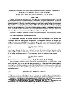
2. The Proposed Reconstruction Method This section details the B-spline surface reconstruction algorithm. A B-spline interpolation surface algorithm is proposed to obtain the blade surface model based on section curves fitting algorithm. In the first step, based on the coordinates of the measured points, a series of section curves is created covering the measured points. In the second step, the surface model is created. The detailed reconstruction process is shown in Figure 1. 2.1. Extracting the Less Measured Points. For the purpose of the rapid and efficient measurement, the less measured points are extracted firstly. Due to the special properties of blades, we usually only get the discrete points of section curves from the blade theoretical model. According to the set compression accuracy, the less measured points are extracted from the discrete points. As shown in Figure 2, eight equally spaced points and two extreme points of the curvature which located on the leading and trailing edge regions, respectively, are selected from the theoretical blade section curve to constitute the basic measured points set. First, a cubic B-spline curve is obtained by interpolating the basic measured points set. Second, the maximum Hausdorff distance [32] is calculated between the B-spline interpolation curve and the theoretical blade section curve. Finally, the point of the maximum Hausdorff distance is added to the basic measured points set. Repeat the above steps until the maximum Hausdorff distance meets the set compression accuracy. The regained basic measured points set is regarded as the less measured points to measure the blade surface. 2.2. Section Curves Fitting. A good result of the reconstruction algorithms usually can reflect the original design idea. For blade surface reconstruction, the shape accuracy of leading and trailing edges and its connection relationship with other parts of blade have an important influence on blade dynamic performance. Therefore, our effort is concentrated on smoothly jointing the leading and trailing edges with the main parts of blade, which can avoid flow disturbance and
International Journal of Aerospace Engineering
3 Measure the less measured points of the section curves Calculate the throat and key geometric points from the less measured points Section curves divided into four segments by the throat and key geometric points Four segments described by different algorithms Obtain the corrected less measured points (a) Section curves fitting
Calculate the matched points of the corrected less measured points Interpolate the section and streamwise direction curves by different algorithms Extend the interpolation curves in two parametric directions Obtain the reconstructed interpolation surface (b) Surface patch reconstruction
Figure 1: Surface reconstruction.
Throat point
Trailing edge region Suction side
Trailing edge region Suction side
Pressure side
Pressure side
Key geometric point Leading edge region
Leading edge region
Figure 2: Basic measured points set.
flow separation regions [33]. Hamakhan and Korakianitis [34] proposed the continuous slope of curvature or the thirdderivative continuity in the joint points of section curves, which can be used to avoid flow separation. They used a set of high order curves to ensure the continuity at joint points, which takes a lot of computation time.
Figure 3: Section curve segmentation.
In this paper, we divide the blade section curve into four segments, trailing edge region, leading edge region, suction side, and pressure side, which are described by two kinds of curve types. As shown in Figure 3, the trailing edge region starts from the throat point at the suction side. For the pressure side, there is no corresponding throat point,
4
International Journal of Aerospace Engineering A 𝜃
𝛼1
e lin er b am
a1
b
C
o
i 𝛽1 𝛽1k
𝛽2k 𝛽2
B
𝛿
b1
𝛽s
b2
at1
𝛽1 a2
bt1
a3
b3
a4
b4
a5
a6 at2
b5
a7
b6
b7
b8
Figure 5: Points alignment.
Figure 4: Geometric parameters of blade section curve.
and a key geometric point is selected as the joint point to describe the other boundary of trailing edge region. A similar technique is used to describe the leading edge region. For the selection of key geometric points, the change rate of less measured points curvature is applied. A cubic B-spline interpolation curve is used to calculate the curvature. The mathematical formula of cubic B-spline curve function can be expressed: 𝑛
𝑆𝑘 (𝑡) = ∑ 𝐵𝑖 𝑁𝑖,𝑘 (𝑡) ,
(1)
𝑖=0
where 𝑘 is the order, 𝐵𝑖 are the controls points, 𝑁𝑖,𝑘 are the normalized B-spline basis functions, and 𝑡 are the parameters. The recurrence formula of the derivative is 𝑑𝑝 𝑆 (𝑡) 𝑑𝑡𝑝 𝑘 𝑛
(2)
(𝑝)
= 𝑘 (𝑘 − 1) ⋅ ⋅ ⋅ (𝑘 − 𝑝 + 1) ∑ 𝐵𝑖 𝑁𝑖,𝑘−𝑝+1 (𝑡) , 𝑖=−𝑘+𝑝
where 𝐵𝑖(0) = 𝐵𝑖 , 𝑝 = 0, (𝑝) 𝐵𝑖
(𝑝−1)
(𝑝−1)
− 𝐵𝑖−1 𝐵 = 𝑖 , 0 ≤ 𝑝 ≤ 𝑘, 𝑡𝑖+𝑘−𝑝+1 − 𝑡𝑖
(3)
where 𝑝 is the order of the derivative. The curvature can be calculated by 𝐶𝑘 (𝑡) =
𝑆𝑘 (𝑡)
2 (3/2)
[1 + (𝑆𝑘 (𝑡) ) ]
,
(4)
where 𝑆𝑘 (𝑡) is the first derivative and 𝑆𝑘 (𝑡) is the second derivative. For the selection of throat point, as shown in Figure 4, the throat diameter 𝑜 is calculated by the throat/chord (𝑜/𝑏): 𝐶𝐿 𝑜 , = 2 𝑏 2cos 𝛽2 (tan 𝛽1 − tan 𝛽2 )
(5)
where 𝐶𝐿 is the tangential lift coefficient, 𝛽1 is inlet flow angle, and 𝛽2 is outlet flow angle. The tangential lift coefficient 𝐶𝐿 usually ranged from 0.8 to 1.2 [35]. The main parts (suction side and pressure side) of blade section curve are described by a cubic B-spline fitting algorithm firstly, which can get the parameters of joints points. The blade trailing edge region and leading edge region are described with the following equation, respectively: 𝑦 = 𝑎0 + 𝑎1 𝑥 + 𝑎2 𝑥2 + 𝑎3 𝑥3 + 𝑎4 𝑥4 𝑘1 [𝑥 − 𝑥 (𝑝𝑡𝑠 )] + 𝑎5 𝑥5 𝑘2 [𝑥 − 𝑥 (𝑝𝑡𝑠 )] + 𝑎6 𝑥6 𝑘3 [𝑥 − 𝑥 (𝑝𝑡𝑝 )]
(6)
+ 𝑎7 𝑥7 𝑘4 [𝑥 − 𝑥 (𝑝𝑡𝑝 )] , where 𝑘1 , 𝑘2 , 𝑘3 , and 𝑘4 are exponential functions [36], resulting in terms of increasing importance as we approach points 𝑝𝑡𝑠 and 𝑝𝑡𝑝 ; 𝑝𝑡𝑠 and 𝑝𝑡𝑝 are joint points on the suction and pressure side. This equation contains eight unknown coefficients (𝑎0 , . . . , 𝑎7 ) and four unknown parameters (𝑘1 , . . . , 𝑘4 ). These can be calculated by the conditions of point, first-, second-, and third-derivative continuity of blade section curves at the joint points, and prescribing the region shapes using the least squares minimization. 2.3. Rectangular Curve Meshes Construction. Due to the different shapes of blade section curves, the less measured points may not be same for all section curves. In order to reconstruct the blade surface model, all section curves should have the same number of points and be interpolated by reconstruction algorithm. However, the points not only have the same number in each section, but also should correspond to each other in two different sections. As shown in Figure 5, the two adjacent section curves have different measured points (𝑎1 , . . . , 𝑎𝑛 ) and (𝑏1 , . . . , 𝑏𝑚 ). First, we connect the boundary points (𝑎1 , 𝑏1 ) and (𝑎𝑛 , 𝑏𝑚 ), and the intersection point is 𝑜. And then calculate the angles (𝛼1 , . . . , 𝛼𝑛 ) and (𝛽𝑖 , . . . , 𝛽𝑚 ) formed with the boundary connection line and the lines connecting intersection point 𝑜 and points (𝑎1 , . . . , 𝑎𝑛 ) and (𝑏1 , . . . , 𝑏𝑚 ), respectively, decide the corresponding relationship between points 𝑎𝑖 and 𝑏𝑗 by comparing the difference between the angles 𝛼𝑖 and 𝛽𝑗 . Points 𝑎𝑖 and 𝑏𝑗 are seen as a pair if the difference between the angles
International Journal of Aerospace Engineering
5
satisfies the desired accuracy. For the rest of measured points on the section curve, we add points on the other section curve as their corresponding points if the distance between the points and the line connecting intersection point and measured points are minimum. For example, the point 𝑎𝑡1 is added to the measured points list (𝑎1 , . . . , 𝑎𝑛 ) and taken as a pair with the point 𝑏5 . We select the adjacent section curves to add the points in each iteration, which start from the section curve which has the most measured points. The corresponding relationship between the points on different section curves will be obtained after the iteration process.
𝑢1 = 𝑢𝑙−1 − 1, 𝑢𝑙+2 = 𝑢4 + 1,
(7)
𝑢𝑙+3 = 𝑢5 + 1, 𝑢𝑙+4 = 𝑢6 + 1. For the streamwise direction open curve, 𝑢3+𝑖 = 𝑑̃𝑖 , 𝑙 = 𝑛 + 2. Consider 𝑢0 = 𝑢1 = 𝑢2 = 𝑢3 = 0, 𝑢𝑙+1 = 𝑢𝑙+2 = 𝑢𝑙+3 = 𝑢𝑙+4 = 1.
(8)
The problem of interpolating 𝑛 + 1 points into a cubic Bspline curve can be described as follows: 𝑛+2
𝑝𝑘 = ∑ 𝐵𝑖 𝑁𝑖,3 (𝑢𝑘 ) ,
(0 ≤ 𝑘 ≤ 𝑛) .
(9)
𝑖=0
The B-spline interpolation surface is the extension of Bspline curve in two parametric directions, whose equation is as follows: 𝑛
𝑚
𝑄 (𝑢, V) = ∑ ∑ 𝐵𝑖,𝑗 𝑁𝑖,3 (𝑢) 𝑀𝑗,3 (V) , 𝑖=0 𝑗=0
250
200 150 100 50 0 20
10 y(
0 mm −10 ) −20
𝑢0 = 𝑢𝑙−2 − 1, 𝑢2 = 𝑢𝑙 − 1,
Figure 6: The measuring equipment.
z (mm)
2.4. Blade Surface Reconstruction. Based on the corresponding points, we can get a cubic B-spline interpolation surface. In order to get a cubic B-spline interpolation curve, we use the centripetal method to parameterize knots 𝑢𝑖 (𝑖 = 0, 1, . . . , 𝑚), 𝑚 = 𝑛+6 of measured points 𝑝𝑖 (𝑖 = 0, 1, . . . , 𝑛). These points 𝑝𝑖 (𝑖 = 0, 1, . . . , 𝑛) have the corresponding knots value 𝑢3+𝑖 (𝑖 = 0, 1, . . . , 𝑛). Let 𝑑𝑖 = 𝑑𝑖−1 + |𝑝𝑖 − 𝑝𝑖−1 |1/2 (𝑖 = 1, 2, . . . , 𝑛) and 𝑑0 = 0, Then 𝑑̃𝑖 = 𝑑𝑖 /𝑑𝑛 . For the closed section curve, 𝑢3+𝑖 = 𝑑̃𝑖 , 𝑙 = 𝑛+2. Consider the following:
−30
−40
−20
0
20
40
60
m)
x (m
Figure 7: The less measured points.
points are used to construct the B-spline interpolation curve and then extended into B-spline interpolation surface of blade. The deviation between the theoretical surface and the B-spline interpolation surface is calculated as the shape error. If the error is smaller than the given tolerance, the reconstructed interpolation surface will be obtained.
3. Case Studies The following sections used two blades to illustrate the efficacy of the proposed algorithm for reconstructing surface. The two blades of different geometry shapes were measured by a coordinate measuring machine, which is supplied with noncontact laser displacement sensor KEYENCE LK-G150 as shown in Figure 6. In this paper, the less measured points are obtained from the theoretical blade section curve under compression accuracy of 0.05 mm. We take two aspects into consideration to validate the reconstruction algorithm, the computation time, and the shape error.
(10)
where 𝑁𝑖,3 (𝑢) and 𝑀𝑗,3 (V) are the B-spline basis functions in the parametric 𝑢 and V directions, respectively. 𝐵𝑖,𝑗 are the control vertices of the rectangular meshes. In reverse engineering, the shape error between the reconstruction surface model and theoretical model is significant. For the blade reconstruction surface, the measured
3.1. The Reconstruction of a Simple Blade. When the measurement step is set as 0.1 mm, the normal measured points of six section curves for the simple blade were 12011. As shown in Figure 7, the less measured points were 394 and the compression rate can reach 96.7%. The less measured points were processed to select the key geometric points shown in Figure 8. For the selection of throat points, 𝐶𝐿 is 0.8, 0.86,
6
International Journal of Aerospace Engineering Table 1: Comparison results of multialgorithms for simple blade.
Model
Points 394 12011 12011 12011
Simple blade
Method Proposed method Proposed method Xie [15] Kineri [16]
Max error/mm 0.138 0.179 0.335 0.505
Average error/mm 0.012 0.02 0.02 0.02
0.8
z (mm)
0.7
Curvature
0.6 0.5 0.4 0.3
250 200 150 100 50 0 20 15
Standard deviation/mm 0.028 0.028 0.03 0.029
10 5 y ( 0−5−10 mm ) −15−20−25 −40
−20
20 0 ) m x (m
Time/s 186.1 528.5 519.4 440.8
40
60
Figure 10: Blade reconstruction model. 0.2 0.1 0
0
0.1
0.2
0.3
0.4
0.5 t
0.6
0.7
0.8
0.9
1
Key geometric point
Figure 8: Key geometric points selection.
250
z (mm)
200 150 100 50 0 20
Figure 11: Zebra mapping effect of the blade surface. 10 y(
0 mm −10 −20 )
−30
−40
−20
0
20
40
60
m)
x (m
Figure 9: Rectangular grids.
0.96, 1.06, 1.17, and 1.2 from the hub to tip of blade section curves. In order to generate the rectangular curve meshes, measured points in each section curve were matched as a pair and 284 points were added (Figure 9). When the continuous curvature is used to check the continuity of blade surface, the reconstructed surface model (Figure 10) could be imported to the CATIA software to analyze the continuity of surface based on the reflection lines of the zebra mapping. Figure 11 shows the zebra mapping with regular density, which certifies the curvature of surface is continuous. The application of the proposed algorithm enabled the originally independent section curves to be
integrated into a smooth blade surface. Simultaneously, continuity and geometric information required for design could be guaranteed by the section curves fitting. To analyze the reconstruction surface model accuracy, the shape error can be obtained accurately by a comparison between the reconstruction surface model and the theoretical model using Geomagic software. The comparison result, as shown in Figure 12, shows that maximum error is mainly distributed in the leading and trailing edges. This phenomenon indicates that the leading and trailing edges have larger machining error than the other parts of blade and it is possible to improve the accuracy by adding more measured points of these edges. Similarly, we also compare the proposed method and Xie [15] and Kineri [16] under normal measured points (Figure 13) and the comparison results are shown in Table 1. Compared with other algorithms, the proposed algorithm with less measured points has better accuracy of reconstruction surface under less time. Generally, the more the
International Journal of Aerospace Engineering
7 0.139
0.121 0.102 0.084 0.065 0.047 0.028
−0.028 −0.047 −0.065 −0.084 −0.102 −0.121 −0.139
Figure 12: Shape error. 0.536
0.715
0.715
0.451
0.601
0.601
0.367
0.488
0.488
0.282
0.375
0.197
0.262 0.149
0.375 0.262
0.113 0.028 −0.028 −0.113 −0.197
−0.375
−0.375 −0.488
−0.282 −0.367 −0.451 −0.536 (a) The proposed method
0.149 0.036 −0.036 −0.149 −0.262
0.036 −0.036 −0.149 −0.262
(b) Xie [15]
−0.601
−0.488 −0.601
−0.715
−0.715 (c) Kineri [16]
Figure 13: Shape error of different methods for simple blade.
points we use, the higher the fitting accuracy will be and the longer the computation time will be. The reason for this phenomenon is that the proposed method not only improves the reconstruction accuracy by adding the matched points but also reserves more details on blade edges while the other methods only improve the overall reconstruction accuracy. In addition, the machining error and measurement error will also lead to large error of the reconstruction models. It is difficult to give the accurate performance of the computation time. The main reason is that the computation time largely depends on the computer performance and the written programs. Therefore, the absolute value of each CPU time is not interesting. Only the tendency between the algorithms needs to be noticed. 3.2. The Reconstruction of a More Complex Blade. The proposed surface reconstruction algorithm also has been tested
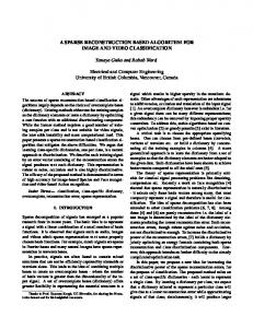
by using a more complex blade which was measured by 136 less measured points. The normal measured points of five section curves were 11286 under the measurement step set as 0.03 mm, and the compression rate is 98.8%. First, we directly identified the section curve segmentations through the key geometric points and throat point, and then the points rectangular meshes are generated for reconstructing a Bspline surface, which are shown in Figures 14–16. The whole surface reconstruction procedures have been successfully applied to the given measured points (Figure 17). A good quality of continuity was observed by investigating zebra mapping of the reconstructed surface, as shown in Figure 18. The 𝐶2 continuity is achieved for Bspline interpolation surface based on the continuous section curves. Error analysis of the reconstruction blade surface was carried out to check the reconstruction accuracy as shown in Figure 19. The maximum error, similarly, mainly distributed
8
International Journal of Aerospace Engineering Table 2: Comparison results of multialgorithms for complex blade.
Model
Points 136 11286 11286 11286
Max error/mm 0.112 0.348 0.348 0.389
Average error/mm 0.017 0.016 0.017 0.018
210
210
200
200
190
190
z (mm)
z (mm)
Complex blade
Method Proposed method Proposed method Xie [15] Kineri [16]
180
170
160 5
160 5 m) −5
−10
−20
−10
10 mm)
0
20
Time/s 314.6 557.6 582.7 529.1
180
170
0 y( m
Standard deviation/mm 0.024 0.062 0.063 0.061
0 y( m
30
m) −5
x(
−10
−20
−10
10 0 ) m m x(
20
30
Figure 16: Rectangular meshes.
Figure 14: The measured points model. 14
12
z (mm)
Curvature
10 8 6 4
0 y (m
m) −5
2 0
210 205 200 195 190 185 180 175 170 165 160 5
−10
−20
−10
10 0 m) m ( x
Figure 17: The reconstruction model. 0
0.1
0.2
0.3
0.4
0.5 t
0.6
0.7
0.8
0.9
1
Key geometric point
Figure 15: Key geometric points.
in the leading and trailing edges. More than two-thirds of the reconstruction model has a maximum deviation of 0.044 mm from the theoretical model. For the comparison with the other existing algorithms, the 3D comparison analysis results between the theoretical model and the reconstruction model are shown in Figure 20 and Table 2. From the comparative analysis results of the two blades, it can be seen that the reconstructed surface of proposed algorithm can meet the accuracy requirements. The error distribution of leading and trailing edges is larger than the other parts of blade surface. Therefore, the reconstruction
Figure 18: Zebra mapping effect.
20
30
International Journal of Aerospace Engineering
9 0.1200
0.1010 0.0820 0.0630 0.0441 0.0251 0.0061 −0.0061 −0.0251 −0.0440 −0.0630 −0.0820 −0.1010 −0.1200
Figure 19: Shape error of the reconstruction model. 0.843
0.843
0.710 0.576
0.710 0.576
0.443 0.309
0.443 0.309
0.176 0.042 −0.042
0.176 0.042 −0.042
−0.176
−0.176
−0.309 −0.443
−0.309 −0.443
−0.576
−0.576
−0.710 −0.843
−0.710 −0.843
(a) The proposed method
(b) Xie [15] 0.844
0.710 0.577 0.443 0.309 0.176 0.042 −0.042 −0.176 −0.309 −0.443 −0.577 −0.710 −0.844 (c) Kineri [16]
Figure 20: Shape error of different methods for complex blade.
accuracy will be improved by increasing the number of measured points of leading and trailing edges and improving the machining accuracy of these edges. In order to directly obtain the reconstruction surface model for blade
to the given measured points, the number and position of points that already matched can be regarded as the more reasonable less measured points to measure blade surface again.
10
4. Conclusions A blade surface reconstruction algorithm was proposed and applied in this paper. Reconstruction process has several steps including segmentation of section curves with consideration of the design information to avoid flow disturbance, merging of section curves according to the B-spline curve curvature continuity, and alignment of measured points with a required accuracy. By applying this algorithm to reconstruct blade surface from less measured points, the aerodynamic performance of blade is ensured by considering the design information and curvature continuity. Another advantage of this work is that the reasonable number and position of paired points could be obtained efficiently, which can be regarded as the measured points to measure and construct a reconstruction blade surface directly. The proposed reconstruction algorithm was applied to two example blades. The shapeerror results indicate that the accuracy of the algorithm for main parts of blade with smaller curvature variation can be well controlled. However, for sharp edges of blade with more curvature variation achieving high accuracies may need more measured points to represent the shape of blade. We believe that the proposed algorithm has the potential to perform all kinds of blades automatically. The algorithm is facile, fast, and simple as demonstrated by our experimental results.
Conflict of Interests The authors declare that there is no conflict of interests regarding the publication of this paper.
Acknowledgment The authors would like to acknowledge a grant from the National Nature Science Foundation of China (Grant no. 51135006).
References [1] T. V´arady, R. R. Martin, and J. Cox, “Reverse engineering of geometric models—an introduction,” Computer-Aided Design, vol. 29, no. 4, pp. 255–268, 1997. [2] P. Benk˝o, G. K´os, T. V´arady, L. Ando, and R. Martin, “Constrained fitting in reverse engineering,” Computer Aided Geometric Design, vol. 19, no. 3, pp. 173–205, 2002. [3] A. Karniel, Y. Belsky, and Y. Reich, “Decomposing the problem of constrained surface fitting in reverse engineering,” ComputerAided Design, vol. 37, no. 4, pp. 399–417, 2005. [4] M. Yang and E. Lee, “Segmentation of measured point data using a parametric quadric surface approximation,” ComputerAided Design, vol. 31, no. 7, pp. 449–457, 1999. [5] S. P. Lim and H. Haron, “Surface reconstruction techniques: a review,” Artificial Intelligence Review, vol. 42, no. 1, pp. 59–78, 2014. [6] W. Sun, C. Bradley, Y. F. Zhang, and H. T. Loh, “Cloud data modelling employing a unified, non-redundant triangular mesh,” Computer-Aided Design, vol. 33, no. 2, pp. 183–193, 2001. [7] V. Sangveraphunsiri and K. Sritrakulchai, “The development of a technique for 3D complex surface reconstruction from
International Journal of Aerospace Engineering unorganized point cloud,” International Journal of Advanced Manufacturing Technology, vol. 33, no. 7-8, pp. 772–781, 2007. [8] H.-T. Yau, T.-J. Yang, and H.-Z. Jian, “A region-growing algorithm using parallel computing for surface reconstruction from unorganized points,” Advances in Engineering Software, vol. 59, pp. 29–37, 2013. [9] L. Di Angelo, P. Di Stefano, and L. Giaccari, “A new meshgrowing algorithm for fast surface reconstruction,” ComputerAided Design, vol. 43, no. 6, pp. 639–650, 2011. [10] C. Buchart, D. Borro, and A. Amundarain, “GPU local triangulation: an interpolating surface reconstruction algorithm,” Computer Graphics Forum, vol. 27, no. 3, pp. 807–814, 2008. [11] Y. J. Kil and N. Amenta, “GPU-assisted surface reconstruction on locally-uniform samples,” in Proceedings of the 17th International Meshing Roundtable, pp. 369–385, Springer, Berlin, Germany, 2008. [12] J.-Y. Lai and W.-D. Ueng, “Reconstruction of surfaces of revolution from measured points,” Computers in Industry, vol. 41, no. 2, pp. 147–161, 2000. [13] H. Park, “An approximate lofting approach for B-spline surface fitting to functional surfaces,” The International Journal of Advanced Manufacturing Technology, vol. 18, no. 7, pp. 474–482, 2001. [14] W.-D. Ueng, J.-Y. Lai, and J.-L. Doong, “Sweep-surface reconstruction from three-dimensional measured data,” Computer Aided Design, vol. 30, no. 10, pp. 791–805, 1998. [15] W.-C. Xie, X.-F. Zou, J.-D. Yang, and J.-B. Yang, “Iteration and optimization scheme for the reconstruction of 3D surfaces based on non-uniform rational B-splines,” Computer-Aided Design, vol. 44, no. 11, pp. 1127–1140, 2012. [16] Y. Kineri, M. Wang, H. Lin, and T. Maekawa, “B-spline surface fitting by iterative geometric interpolation/approximation algorithms,” Computer-Aided Design, vol. 44, no. 7, pp. 697–708, 2012. [17] J. Dan and W. Lancheng, “An algorithm of NURBS surface fitting for reverse engineering,” The International Journal of Advanced Manufacturing Technology, vol. 31, no. 1-2, pp. 92–97, 2006. [18] V. Weiss, L. Andor, G. Renner, and T. V´arady, “Advanced surface fitting techniques,” Computer Aided Geometric Design, vol. 19, no. 1, pp. 19–42, 2002. [19] Z. Yin, “Reverse engineering of a NURBS surface from digitized points subject to boundary conditions,” Computers & Graphics, vol. 28, no. 2, pp. 207–212, 2004. [20] K.-Y. Lin, C.-Y. Huang, J.-Y. Lai, Y.-C. Tsai, and W.-D. Ueng, “Automatic reconstruction of B-spline surfaces with constrained boundaries,” Computers & Industrial Engineering, vol. 62, no. 1, pp. 226–244, 2012. [21] A. G´alvez and A. Iglesias, “Particle swarm optimization for nonuniform rational B-spline surface reconstruction from clouds of 3D data points,” Information Sciences, vol. 192, pp. 174–192, 2012. [22] W. Ma and J.-P. Kruth, “NURBS curve and surface fitting for reverse engineering,” The International Journal of Advanced Manufacturing Technology, vol. 14, no. 12, pp. 918–927, 1998. [23] A. Abbas, A. Nasri, and T. Maekawa, “Generating B-spline curves with points, normals and curvature constraints: a constructive approach,” The Visual Computer, vol. 26, no. 6–8, pp. 823–829, 2010.
International Journal of Aerospace Engineering [24] D.-J. Yoo, “Three-dimensional surface reconstruction of human bone using a B-spline based interpolation approach,” ComputerAided Design, vol. 43, no. 8, pp. 934–947, 2011. [25] S. Yuwen, G. Dongming, J. Zhenyuan, and L. Weijun, “B-spline surface reconstruction and direct slicing from point clouds,” The International Journal of Advanced Manufacturing Technology, vol. 27, no. 9-10, pp. 918–924, 2006. [26] Y. F. Wu, Y. S. Wong, H. T. Loh, and Y. F. Zhang, “Modelling cloud data using an adaptive slicing approach,” Computer-Aided Design, vol. 36, no. 3, pp. 231–240, 2004. [27] Y. F. Zhang, Y. S. Wong, H. T. Loh, and Y. F. Wu, “An adaptive slicing approach to modelling cloud data for rapid prototyping,” Journal of Materials Processing Technology, vol. 140, no. 1–3, pp. 105–109, 2003. [28] S.-W. Hsiao and R.-Q. Chen, “A study of surface reconstruction for 3D mannequins based on feature curves,” Computer-Aided Design, vol. 45, no. 11, pp. 1426–1441, 2013. [29] T. Li, X. Shi, Y. Zhang et al., “The imperfect sample points of interpolation based on B-spline suface reconstruction,” in Proceedings of the 6th International Congress on Image and Signal Processing (CISP ’13), pp. 522–526, Hangzhou, China, December 2013. [30] F. Javidrad and A. R. Pourmoayed, “Contour curve reconstruction from cloud data for rapid prototyping,” Robotics and Computer-Integrated Manufacturing, vol. 27, no. 2, pp. 397–404, 2011. [31] Z. Chen, F. Zhang, X. Qu, and B. Liang, “Fast measurement and reconstruction of large workpieces with freeform surfaces by combining local scanning and global position data,” Sensors, vol. 15, no. 6, pp. 14328–14344, 2015. [32] Y.-B. Bai, J.-H. Yong, C.-Y. Liu, X.-M. Liu, and Y. Meng, “Polyline approach for approximating Hausdorff distance between planar free-form curves,” Computer-Aided Design, vol. 43, no. 6, pp. 687–698, 2011. [33] G. N. Koini, S. S. Sarakinos, and I. K. Nikolos, “A software tool for parametric design of turbomachinery blades,” Advances in Engineering Software, vol. 40, no. 1, pp. 41–51, 2009. [34] I. A. Hamakhan and T. Korakianitis, “Aerodynamic performance effects of leading-edge geometry in gas-turbine blades,” Applied Energy, vol. 87, no. 5, pp. 1591–1601, 2010. [35] T. P. Korakianitis, A design method for the prediction of unsteady forces on subsonic, axial gas-turbine blades [Ph.D. thesis], Massachusetts Institute of Technology, Cambridge, Mass, USA, 1987. [36] B. H. Wegge, Prescribed curvature blade design and optimization of three dimensional turbine blades [Masters thesis (SM) in Mechanical Engineering], Washington University in St. Louis, St. Louis, Mo, USA, 2001.
11
International Journal of
Rotating Machinery
Engineering Journal of
Hindawi Publishing Corporation http://www.hindawi.com
Volume 2014
The Scientific World Journal Hindawi Publishing Corporation http://www.hindawi.com
Volume 2014
International Journal of
Distributed Sensor Networks
Journal of
Sensors Hindawi Publishing Corporation http://www.hindawi.com
Volume 2014
Hindawi Publishing Corporation http://www.hindawi.com
Volume 2014
Hindawi Publishing Corporation http://www.hindawi.com
Volume 2014
Journal of
Control Science and Engineering
Advances in
Civil Engineering Hindawi Publishing Corporation http://www.hindawi.com
Hindawi Publishing Corporation http://www.hindawi.com
Volume 2014
Volume 2014
Submit your manuscripts at http://www.hindawi.com Journal of
Journal of
Electrical and Computer Engineering
Robotics Hindawi Publishing Corporation http://www.hindawi.com
Hindawi Publishing Corporation http://www.hindawi.com
Volume 2014
Volume 2014
VLSI Design Advances in OptoElectronics
International Journal of
Navigation and Observation Hindawi Publishing Corporation http://www.hindawi.com
Volume 2014
Hindawi Publishing Corporation http://www.hindawi.com
Hindawi Publishing Corporation http://www.hindawi.com
Chemical Engineering Hindawi Publishing Corporation http://www.hindawi.com
Volume 2014
Volume 2014
Active and Passive Electronic Components
Antennas and Propagation Hindawi Publishing Corporation http://www.hindawi.com
Aerospace Engineering
Hindawi Publishing Corporation http://www.hindawi.com
Volume 2014
Hindawi Publishing Corporation http://www.hindawi.com
Volume 2014
Volume 2014
International Journal of
International Journal of
International Journal of
Modelling & Simulation in Engineering
Volume 2014
Hindawi Publishing Corporation http://www.hindawi.com
Volume 2014
Shock and Vibration Hindawi Publishing Corporation http://www.hindawi.com
Volume 2014
Advances in
Acoustics and Vibration Hindawi Publishing Corporation http://www.hindawi.com
Volume 2014