Proceedings of the World Congress on Engineering 2011 Vol II WCE 2011, July 6 - 8, 2011, London, U.K.
A Remote Microprocessor-Based Monitoring and Control System via Internet in Case Study of Pet Care H. C. Lin, K. H. Pai, C. H. Chen, S. Y. Lai, Y. C. Lai Abstract—Since the past years, the microprocessor (8051) has been still playing an indispensable role as a controller in industry applications because of fast executing process, low-cost, small size and low power consumption, etc. It, however, usually lacks of long distance transmission, graphical interface and vision. On the other hand, VB is now a very popular software package for graphical interface design due to easy exploring and low price. Combining both superiorities as above, this paper develops a remote visional microprocessor-based monitoring and control platform using VB graphical interface. The nearby PC (server) can collect real-time sensing signals from the 8051 through RS232 and transmit it to remote PCs (client) for on line monitoring mechanism via Internet. Also, the client can send the control signals to the server and thus control the 8051. The real-time case study for feeding care in the Pet House is provided to verify its well performance and remote Web-based capability in term of fast, simple and robust performance.
Index Terms—GUI, wireless, VB, 8051, monitoring and control I. INTRODUCTION
T
HE The microprocessor 8051 has been still widely applied in industry since its announcement in 1980 [1-13]. That is why many microprocessor-related courses still open in electrical fields in Universities around the world. With increasing demand of industrial e-platform facilities and friendly operation, it should be considered to be upgraded to a graphical interface and remote communication capability. In view of graphical programming, VB has been one of the most popular software packages in graphic user interface (GUI) design under Windows environment. That is why there are a large number VB applications can be found in a variety of areas [14-22].
Manuscript received Dec. 9, 2010; revised Feb. 17, 2011. This work was supported by the National Science Council of the Republic of China, Taiwan under Grant No. NSC 99-2622-E-167 -017 -CC3. H. C. Lin is with the Department of Electronic Engineering, National Chin-Yi University of Technology, Taiwan (e-mail:
[email protected]). K. H. Pai is with the Department of Electronic Engineering, National Chin-Yi University of Technology, Taiwan (e-mail:
[email protected]). C. H. Chen is with the Department of Automation Engineering, Chienkuo Technology University, Taiwan (e-mail:
[email protected]). S. Y. Lai is with the Department of Electronic Engineering, National Chin-Yi University of Technology, Taiwan (e-mail:
[email protected]). Y. C. Lai is with the Department of Electronic Engineering, National Chin-Yi University of Technology, Taiwan (e-mail:
[email protected]).
ISBN: 978-988-19251-4-5 ISSN: 2078-0958 (Print); ISSN: 2078-0966 (Online)
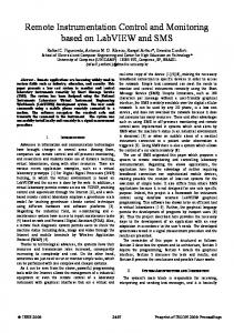
This study describes how to set up a visional microprocessor-based platform using graphical interface with a camera via Internet. The proposed system can perform on line real-time monitoring and control function. The PC and 8051 can communicate with each other via RS232 radio modems up to more than 150M distance wirelessly. In the case study for pet feeding care, the graphical interface is designed to provide commands to control the Pet House and also to display real-time information from the Pet House on line. Accordingly, the microprocessor can not only carry on its own task but also allow remote PC to monitor or control its programming process. The conventional microprocessor can be thus delivered into many e-platform applications by the supplementary functions. This paper is organized as follows. Section II gives a profile of the proposed system hardware structure. Section III describes the system software, including GUI, server and client programming, and 8051 programming. Particularly, the communication among the server, client and 8051 is demonstrated and discussed for details. In Section IV, the experimental results are presented to confirm that the proposed scheme is capable of remote on-line monitoring and control performance. Conclusions and recommendations are given in Section V. II. PROFILE OF THE SYSTEM STRUCTURE The structure of the proposed on-line monitoring and control system is shown in Fig. 1, and the monitored and controlled object, i.e., Pet House, is shown in Fig. 2. The A/D converter and 8255 (programmable Peripheral Interface) is to convert analog signal (amount of feed and drinking water) into an 8-bit digital signal that is input to the microprocessor (8051). Based on the RS232 radio modem, the communication distance between the nearby PC (server) and Pet House can be up to 150 M using 1Mbps transmission rate, and the distance can be further extended to 280M using 250Kbps. The remote PC (client) can connect with the nearby PC (server) via Internet using TCP/IP. Therefore, the remaining amount of feed and water in the Pet House can be transmitted to the nearby PC (server) and remote PC (client) for instant display. Additionally, the control signals such as the feeding amount or light control from the server or client can be sent to the microprocessor (8051).
Fig. 1 Structure of the proposed system hardware
WCE 2011
Proceedings of the World Congress on Engineering 2011 Vol II WCE 2011, July 6 - 8, 2011, London, U.K.
Fig. 2 Sketch of Pet House Fig. 3 depicts the profile of I/O communication interface for details among the client, server, 8051, 8255 and Pet House. The control signals including connection request, manual feeding, automation control, feeding amount, and light control from the client or server can be received by 8051 to operate the Pet House. Moreover, the monitoring signals from 8051 like drinking water level, feed level, and feed status in the bowl can be transmitted to the server and client for real-time display. Fig. 4 reveals the profile of water and feed level detector. The analog voltage from the variable-resistor connecting with the pulley is proportional to the amount of water or feed level and is converted into a digital number via the A/D converter. For the bowl feed detection, there are only two digital states, i.e., high (no feed) or low (feed still available) voltage, that can be read by 8255 directly, shown in Fig. 5.
The main facilities or modules required for the proposed system are as follows. (1) Two PCs. One is used as the server (nearby PC), and the other works as the client (remote PC). (2) VB6.0 for the GUI design, Internet connection, and communication with 8051. (3) One microprocessor (Intel 8051) connected with the server PC via RS232 radio modem. (4) A/D converter module (ADC0804: 8-Bit µP Compatible A/D Converter) with 8255 (Programmable Peripheral Interface). (5) RS232 radio modem (Transceiver module GFSK) for wireless communication. (6) Two detectors for both water and feed level detection. Another detector is used for status checking of bowl feed. (7) A Pet House controlled by 8051 is to provide the pet feed and drinking water. III. DESCRIPTION OF THE SYSTEM SOFTWARE The proposed scheme has developed the remote monitoring and control platform using VB-based GUI and 8051-based control system. The software system mainly includes the GUI, server and client programming, and 8051 programming, more details as follows. III.1 Description of GUI The VB-based GUI builds up a friendly human operation interface and the communication mechanism among the server, client and 8051. From the monitoring and control panel in the server, shown in Fig. 6, the connecting between the server and 8051 will be achieved immediately once the “Start Listening” button is pressed. Consequently, the status of drinking water and feed levels transmitted from the 8051 can be received and displayed on line in both server and client. The bowl feed available or empty in the Pet House can be viewed, too. Moreover, the GUI can determine the feeding way using manual or automatic control function. In conclusion, the control commands are defined and listed in Table 1.
Fig. 3 Profile of I/O signal communication interface
Fig. 4 Profile of water and feed level detector
Fig. 6 Monitoring and control panel in the server
Fig. 5 Profile of bowl feed detector
ISBN: 978-988-19251-4-5 ISSN: 2078-0958 (Print); ISSN: 2078-0966 (Online)
WCE 2011
Proceedings of the World Congress on Engineering 2011 Vol II WCE 2011, July 6 - 8, 2011, London, U.K.
III.2 Illustration of server, client and 8051 programming The programming of server and client is responsible for transmitting control signals to 8051 and also receiving data from 8051. Besides, the real-time images transferred from the camera may be integrated into the GUI in both server and client panels. III.2.1 Server programming The main procedure in the server programming is briefly described as follows, and its flowchart is shown in Fig. 7. Table 1: Definition of control signals Item Control signal 1 Start Connecting 2 Manual Feeding 3 Feeding Amount: More 4 Feeding Amount: Medium 5 Feeding Amount: Less 6 Light On 7 Light Off 8 Motor Right 9 Motor Left 10 Save Automatic Timetable 11 Load Automatic Timetable 12 Automatic On 13 Automatic Off
Command code G 01 03 04 05 06 07 08 09 10 11 12 13
(a) Check if there is a connection request with 8051. If yes, go to next step. Otherwise, repeat the same procedure. (b) Check if last setting exists in Monitoring and Control Panel. If yes, go to Step (c). Otherwise, load previous setting file. (c) Set COM1 as the serial communication via RS232, and determine the transmission rate, i.e., Baud rate per second (Bps), as 9600 that can match the 8051 receiving rate. (d) In this step, three operation branches are working independently as follows. Branch 1: Manual mode i. Check if there is a manual request from the client. If yes, go to Step (iii). Otherwise, go to next step. ii. Check if the manual mode is operated. If yes, go to next step. Otherwise, go back to Step (i) iii. Send the manual command to 8051. iv. Check if the feedback is received from 8051. If yes, go to next step. Otherwise, go back to Step (iii). v. Check if the client is connected. If yes, the feedback from 8051 will be transmitted to the client. Otherwise, go back to Step (i). Branch 2: Automation mode i. Check if Automation mode is selected. If yes, go to next step. Otherwise, repeat the same procedure. ii. Run the automation operation that is to send the control signals to 8051 once the feeding time schedule is up. iii. The automation operation is carried on until it is shut down. III.2.2 Client programming The main procedure in the client programming is briefly described as follows, and its flowchart is shown in Fig. 8.
Fig. 7 Flowchart of server programming Fig. 8 Flowchart of client programming ISBN: 978-988-19251-4-5 ISSN: 2078-0958 (Print); ISSN: 2078-0966 (Online)
WCE 2011
Proceedings of the World Congress on Engineering 2011 Vol II WCE 2011, July 6 - 8, 2011, London, U.K.
(a) Set IP address of the server for Internet connection, including the channel port. (b) Check if the connection with the server is requested. If yes, go to next step. Otherwise, continue the same procedure. (c) Check if the connection is successful. If yes, go to next step. Otherwise, go back to Step (b). (d) Receive data from the server via Winsocks. (e) In this step, three operation branches are working independently as follows. Branch 1: Manual mode i. Check if there is a manual request. If yes, go to next step. Otherwise, repeat the same procedure. ii. Send the manual command to the server. iii. Go back to Step (i). Branch 2: Automation mode i. Check if Automation mode is chosen. If yes, go to next step. Otherwise, repeat the same procedure. ii. Send the automation command to the server. iii. Step (ii) is carried on until the automation operation is shut down. III.3 Illustration of the 8051 programming The microprocessor (8051) is to construct the bridge for communication between the VB and Pet House via RS232 radio modems. The programming flowchart is shown as Fig. 9. The main procedure is briefly described as follows.
(a) Set COM1 as the serial communication with the outside world. SCON is set to as transmission mode 1, and TMOD is set as timer mode 2. All related registers are set as the following table. Table 1: control registers status SCON TMOD SMOD TH1 Bps TI RI 50H 20H 1 FDH 9600 0 0 Note that the value of TH1 is to determine the transmission rate. 8051’s communication operation is chosen as Mode 1 to transmit the message via TXD and to receive the message via RXD. TXD is the transmission bit in the Universal Asynchronous Receiver transmitter (UART), and RXD is the receiving bit. (b) Continue the Step (b) until the connection request from the server is received and then go to next step. (c) The data (amount of both feed and water) is read to the p2 of 8051 from A/D converter, and it is stored temporarily in the serial port buffer (SBUF) ready for transmission to the server. (d) Go back to Step (c) until upon complete transmission of data from UART serial port (TXD) to VB, and TI will be set to 1. (e) Set time delay. (f) Read the SBUF data (feeding amount and time schedule) received from the VB. (g) Go back to Step (f) until upon complete data receiving, and RI will be set to 1. (h) Set time delay. (i) Go back to step(c) until the system is turned off. III.4 Illustration of the data transferring between server and client When the system operation is activated, the data (control or sensor signal) from the server will be transferred to the server immediately. The key commands for communication agreement between client and server are concluded as follows. The communication mechanism between the client and server via Winsocks is shown in Fig. 10. The key points with sequence procedures are briefly illustrated as follows. A: Connecting process (a) The server is waiting for the connection request from the client when it operates “Listening” function. (b) The client operates the “Connect” function to request the connection with the server. (c) Once receipt of connection request by the client, the server will soon activate the “ConnectionRequest” event. (d) The sever operates the “Accept” function. (e) After the connection is complete, the “Connect” event in the client is thus activated. B: Data transmission (a) Once the connection is successful, any side (server or client) can operate “SendData” function to send data to the other side (b) The “DataArrival” event is activated. (c) The receiving end can use “GetData” function to pick up the data. (d) Any side can use “Close” function to disconnect the connection.
Fig. 9 Flowchart of the 8051 programming ISBN: 978-988-19251-4-5 ISSN: 2078-0958 (Print); ISSN: 2078-0966 (Online)
WCE 2011
Proceedings of the World Congress on Engineering 2011 Vol II WCE 2011, July 6 - 8, 2011, London, U.K.
Fig. 12 Setting of Automatic Control Panel Fig. 10 Communication method between the server and client IV. EXPERIMENTAL RESULTS In order to demonstrate the effectiveness of the proposed approach, a variety of real-time monitoring and control operations have been fully illustrated, including system connection, setting of automatic control, display of real-time operation, etc. (a) Connect sever with 8051 The first step to implement the proposed system is to connect server with 8051 via RS232. Once the “Start Listening” button, shown in Fig. 6, is pressed, the connection will be operated immediately whenever the 8051 is standby. Fig. 11 indicates that the system is now working under automatic mode after connection, and every indicator status receiving from 8051 is displayed on line. Note that “Sign up” can set the account and password for the user from the client. On the other hand, “Login” allows the user to access both server and client, including the password change.
(c) Save and load setting In Fig. 13, “Save” button pressed for new setting reveals that the setting for new feeding time schedule and amount can be saved in the preferred route in order to satisfy different feeding requirements. The previous setting file can be also re-loaded by pressing “Load” setting.
Fig. 13 Save new setting (d) Connect client with server The real-time operation of the proposed system in the client after connection is shown in Fig. 14, similar to the server panel in Fig. 11. As can be seen, the monitoring and control panel has provided current status of Pet House, giving information about feeding amount and time schedule, remaining drinking water and feed amount. Moreover, the light in the Pet House can be controlled by the panel. The system can also check if there is still some feed available in the feed bowl.
Fig. 11 Startup of system connection (b) Set automatic control panel The Automatic Control Panel, shown in Fig. 12, is to present more flexible and friendly human-operation interface. Therefore, the feeding time schedule and amount can be modified, providing functions such as Add, Delete, Clear All and Exit. When the modification is done, the setting will be saved in the pre-defined route automatically.
Fig. 14 Client panel after connection ISBN: 978-988-19251-4-5 ISSN: 2078-0958 (Print); ISSN: 2078-0966 (Online)
WCE 2011
Proceedings of the World Congress on Engineering 2011 Vol II WCE 2011, July 6 - 8, 2011, London, U.K.
V. CONCLUSIONS This paper has developed a remote visional monitoring and control platform using 8051 microprocessor-based VB graphical interface via Internet successfully. The proposed scheme in deed provides a sufficient background needed for electrical/automation engineering students or engineers in understanding microprocessor-based control system with Internet-based graphical monitoring and control capability. Particularly, this paper introduces illustrative techniques for data (control or monitoring signals) transmission among the server, client, and microprocessor (8051) using the GUI. Furthermore, the paper provides the idea of real-time applications extended to another disciplines, including installation of camera and voice.
[16]
[17]
[18]
[19]
[20]
REFERENCES [1]
Shi Yuanyuan, Liu Jia, Liu Runsheng, “Single-chip speech recognition system based on 8051 microcontroller core”, IEEE Transactions on Consumer Electronics, Vol. 47, Issue 1, pp.149-153, Feb. 2001. [2] Je-Hoon Lee, Young Hwan Kim, Kyoung-Rok Cho, “A Low-Power Implementation of Asynchronous 8051 Employing Adaptive Pipeline Structure”, IEEE Transactions on Circuits and Systems II: Express Briefs, Vol.55 , Issue 7, pp. 673-677, July 2008. [3] Kumar, U., “C and the 8051: building efficient applications”, IEEE Circuits and Devices Magazine, Vol.16, Issue 2, pp. 35-36, Mar. 2000. [4] Chao Xue, Xiang Cheng, Yang Guo, Yong Lian, “The design of a sub-nanojoule asynchronous 8051 with interface to external commercial memory”, IEEE 8th International Conference on ASIC (ASICON '09), pp. 427-430, Oct. 2009. [5] Groza, B., Murvay, P.-S., Silea, I., Ionica, T., “Cryptographic Authentication on the Communication from an 8051 Based Development Board over UDP”, The Third International Conference on Internet Monitoring and Protection (ICIMP '08), pp. 92-97, June 29-July 5 2008. [6] Chang-Jiu Chen, Wei-Min Cheng, Ruei-Fu Tsai, Hung-Yue Tsai, Tuan-Chieh Wang, “A pipelined asynchronous 8051 soft-core implemented with Balsa”, IEEE Asia Pacific Conference on Circuits and Systems (APCCAS 2008), pp. 976-979, Nov. 30 2008-Dec. 3 2008. [7] Rech, P., Gerardin, S., Paccagnella, A., Bernardi, P., Grosso, M., Sonza Reorda, M., Appello, D., “Evaluating Alpha-induced soft errors in embedded microprocessors”, 15th IEEE International On-Line Testing Symposium (IOLTS 2009), pp. 69-74, 24-26 June 2009. [8] Rech, P., Paccagnella, A., Grosso, M., Sonza Reorda, M., Melchiori, F., Loparco, D., Appello, D., “Evaluating the Impact of DfM Library Optimizations on Alpha-induced SEU Sensitivity in a Microprocessor Core”, IEEE Transactions on Nuclear Science, Vol. 57 , Issue 4 , Part: 1, pp. 2098-2105, Aug. 2010. [9] Leite, F., Balen, T., Herve, M., Lubaszewski, M., Wirth, G., “Using Bulk Built-In Current Sensors and recomputing techniques to mitigate transient faults in microprocessors”, 10th Latin American Test Workshop (LATW '09), pp. 1-6, 2-5 Mar. 2009. [10] Suwartadi, E., Gunawan, C., Setijadi, A., Machbub, C., “First step toward Internet based embedded control system”, 5th Asian Control Conference, Vol. 2, pp. 1226-1231, 20-23 July 2004.
[21] [22]
Software Based On VB And Matlab”, IEEE International Conference on Networking, Sensing and Control (ICNSC 2008) , pp. 808-811, 2008. Yihu Huang, Genmin Zhang, Jinli Wang, “VB-Based Communications and Optimization Design in Beer Fermentation Control System”, International Conference on Measuring Technology and Mechatronics Automatio (ICMTMA '09), Vol. 2, pp. 523-526, 11-12 April 2009. Xueling Bai, Hongmei Zhang, “Design of digital filter based on VB and matlab”, 9th International Conference on Electronic Measurement & Instruments (ICEMI '09), pp. 4-85 - 4-88, 16-19 Aug. 2009. Yaoxiang Li, Zhiping Wang, “A VB-Based Forest Field Data Collection System”, Second International Workshop on Computer Science and Engineering (WCSE '09), vol. 2, pp. 551-554, 28-30 Oct. 2009. Zhao Long, Wang Hao, “A Design of a Random Roll Call System Based on VB”, Second International Conference on Information and Computing Science (ICIC '09), vol. 1, pp. 316-318, 21-22 May 2009. Sanudin, R., Mun, Y.T., Zaki, W.S.W., Wahab, M.H.A., “Wireless appliance control system”, Innovative Technologies in Intelligent Systems and Industrial Applications (CITISIA 2009), pp. 476-479, July 2009. Clark, D., “Visual Basic and the future of Web-application development”, Computer,Vol. 34 , Issue: 8, pp. 16-18, Aug. 2001. Karatza, H., “A Valuable Resource of Programmers Using .NET Technology”, IEEE Distributed Systems Online, Vol. 5 , Issue 6, pp. 4-4, 2004.
[11] Lin, H.C., ”Remote power system harmonics measurement and monitor via the Internet” IEEE Conference on Cybernetics and Intelligent Systems, vol.1, pp. 474-479, 1-3 Dec. 2004. [12] Chao-Hung Chen, Hsiung-Cheng Lin, Ying-Chu Liu, Wei-Chung Hsu, Shin-Ming Chang, “Sufficient sunlight supply for home care using local closed-loop shutter control system”, IEEE International Conference on Systems, Man and Cybernetics (SMC 2008) , pp. 2270-2275, 12-15 Oct. 2008. [13] Lin, H.C., “On line Web-based Maximum Wind Power Monitoring and Control System”, IEEE International Conference on Systems, Man and Cybernetics (SMC '06), Vol.5, pp. 3932-3937, 8-11 Oct. 2006. [14] Changjun Zhu, Xiujuan Zhao, ”Evaluation of Water Quality Based on Artificial Neural Network Using VB”, International Symposium on Information Science and Engieering (ISISE '08), vol. 1, pp. 538-541, 20-22 Dec. 2008. [15] De-An Zhao, Tian-Hong Pan, Jian-Yun Zhu, Qing Wang, “Identification Of Grain Mildewing With ANN Pattern Recognition
ISBN: 978-988-19251-4-5 ISSN: 2078-0958 (Print); ISSN: 2078-0966 (Online)
WCE 2011