A Robust Data Hiding Technique using Multidimensional Lattices J. J. Chae, D. Mukherjee and B. S. Manjunath Department of Electrical and Computer Engineering University of California, Santa Barbara, CA 93106-9560 Email: chaejj, debu,
[email protected] Abstract We describe a data hiding technique which uses noiseresilient channel codes based on multidimensional lattices. A trade-off between the quantity of hidden data and the quality of the watermarked image is achieved by varying the number of quantization levels for the signature and a scale factor for data embedding. Experimental results show that the watermarked image is transparent to embedding for large amounts of hidden data, and the quality of the extracted signature is high even when the watermarked image is subjected to up to 75% Wavelet compression and 85% JPEG lossy compression. These results can be combined with a private key-based scheme to make unauthorized retrieval practically impossible, even with the knowledge of the algorithm.
Keywords: digital watermarking, data hiding, copyright protection, multidimensional lattice quantizer
1 Introduction Motivated by the overwhelming urge for Internet data security, digital watermarking has recently emerged as an important area of research in multimedia data processing. Most multimedia data sources are readily accessible to, and downloadable by, all users of the internet. In such a scenario, a mechanism for data security or copyright protection is essential. Digital watermaking is a technology being developed to ensure security and protection of multimedia data. The purpose of digital watermarking is not to restrict use of multimedia resources, but to resist attack from unauthorized users. A digitally watermarked image is obtained by invisibly hiding a signature information into the host image. The signature is recovered using an appropriate decoding process. The challenge is to simultaneously ensure that the watermarked image be perceptually indistinguishable from the original, and that the signature be recoverable even when the watermarked image has been compressed or transformed by standard image processing operations. Research on digital watermarking can be categorized into two broad classes depending on the data embedding domain. While one is based on embedding data in the spa-
tial domain [1], the other is based on injection in the frequency or transform domain [2,3,4,5,6]. Most of the recent research on watermarking emphasize the transform domain approach. Cox, et. al [2] proposed the spread spectrum coding method for digital watermarking, and used the DCT transform coefficients for data embedding. Their method is very robust to image transformations because they embedded small amounts of information in widely spread frequency bands. Other researchers too have used the transform domain approach, for example, DCT [2,3,4] or the wavelet transform [5,6]. While most of the contemporary research on watermarking concentrates on copyright protection in internet data distribution [7,8], a different kind of watermarking, commonly known as data hiding, is at present receiving considerable attention. Data hiding is intended to hide larger amounts of data into a host source, rather than just to check for authenticity and copyright information [3,6]. In fact, the problem of watermarking or copyright protection is a special case of the generic problem of data hiding, where a small signature is embedded with greater robustness to noise. This paper proposes a robust data hiding technique using channel codes derived from a finite subset of general n-dimensional lattices [9,10,11,12]. In particular we use the D n lattice, which consists of all integer n-tuples with an even sum. As the quantity of embedded data increases, higher order shells of the lattice are included in the channel code to accommodate them. In the proposed approach, a gray-scale image of as much as half the size of the host image is embedded by perturbing the host wavelet coefficients. The embedding and extracting of the digital watermaking system are similar to the encoder and decoder of the digital communication system. Similar to the communication channel noise, the watermarked image might undergo undesirable transformations: for example, intentional manipulations to remove or degrade the quality of the watermarking: or typical signal processing operations such as compression that may affect the watermark. In this paper, we use an wavelet-based compression scheme [13], and the JPEG compression scheme [14] for the manipulation of the watermarked image before attempting retrieval. As own experimental results indicate, there are no visible
noisy vector inside of the decision boundary
possible perturbed vector
s3
s2
o
.
s o i
x
o o
s1
s3 o
o
o
sβ
(a) Possible perturbations
*
x
s2 o Basis Host Vector
.
si o
o s1
os
i+ 1
o
sβ
(b) Estimation from received noisy vector
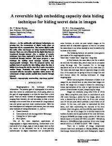
FIGURE 1: Basic embedding methdology. (a) Possible β-ary perturbations of the host vector. (b) Possible noisy vector positions of original perturbed vector si after transformation. (all points shown above are in n-dimensional space)
distortions in the watermarked image, and the recovered signature is similar to the original signature even after 75% wavelet compression and 85% JPEG lossy compression. In the next section we discuss the methodology of multidimensional lattice channel codes. The proposed algorithm using n-dimensional lattices is discussed in Section 3. Experimental results are presented in Section 4 with concluding remarks in Section 5.
2 Multidimensional Lattice Channel Code 2.1 Methodology If the original host image is available, the operations of data injection and retrieval are, in fact, very similar to the channel coding and decoding operations in a typical digital communication system. Channel coding refers to the gamut of signal processing done before transmission of data over a noisy channel. In watermarking in the transform domain, the original host data is transformed, and the transformed coefficients are perturbed by a small amount in one of several possible ways in order to represent the signature data. When the watermarked image is compressed or modified by other image processing operations, noise is added to the already perturbed coefficients. The retrieval operation subtracts the received coefficients from the original ones to obtain the noisy perturbations. The true perturbations that represent the injected data are then estimated from the noisy data as best as possible. In this work, we adopt a vector-based approach to hidden data injection [9,10,11,12],. We group N transform coefficients to form an N-dimensional vector, and modify it by codes that represent the data to be embedded. The motivation for using vector perturbations as opposed to scalar perturbations follows from the realization that higher dimensional constellations usually result in lower probability of error for the same rate of data injection and the same noise statistics. In the Figure 1, ‘x’ represents a
host vector in an N-dimensional space. To embed data from an β-ary source with symbols {s1, s2, ... , sβ}, we perturb the original vector so that the perturbation coincides with one of β corresponding channel codes. The perturbed vector is denoted by one of the ‘o’s in the Figure 1 depending on the particular source symbol it represents. After the watermarked image has undergone compression or other transformations, a perturbed vector representing, for example symbol si in the diagram, may be received as a noisy vector ‘*’ in Figure 1 (b). It is then an estimation problem to extract the transmitted symbol from the vector received. Assuming an additive Gaussian noise model, the received vector is decoded as representing the symbol whose channel code it is closest to in Euclidean distance. Codes derived as subsets of multidimensional lattices have been shown to be very efficient for channel coding. In the following, we describe the general concept of lattices, and in particular, the D 4 lattice that was used in our data embedding algorithm.
2.2 Lattice Structures The Voronoi regions of various n-dimensional lattices can be used to construct n-dimensional quantizer cells for uniformly distributed inputs. It has been shown by Conway and Sloane [9,12] that some of these lattices produce very good channel codes, and yield high values of nominal coding gain. That is, for the same power constraint on the channel, the channel codes are maximally separated from each other so that they are most robust to noise. The lattices considered here are the root lattices and their duals, namely An , A∗ n , D n , D∗ n , E 6 , E8 , etc. If a1, ..., an are n linearly independent vectors in an m-dimensional Euclidean space with m ≥ n , the set of all vectors x = u 1 a1 + … + u n a n
(1)
where u 1 , ...,u n are arbitrary integers, constitute an ndimensional root lattice Λn [9,10,12]. Further, if Λ is a latn tice in ℜ , the dual lattice Λ∗ [12], consists of all points x
in the span of Λ such that x ⋅ y ∈ Z for all y ∈ Λ . Some common lattices and definitions are presented below. For n ≥ 1 , A n is the n-dimensional lattice consiting of +1 the points ( x 0, x 1, …, x n ) in Z n with ∑ x i = 0 . For n ≥ 2 , D n consists of the points ( x 1, x 2, …, x n ) in n Z with ∑ x i even. In other words, if we color the integer lattice points alternately red and blue in a checkerboard coloring, D n consists of the red points. In 4 dimensions the D 4 lattice is known to yield the best coding gain. E 6 , E 8 , and Λ16 lattices give very good channel coding gains in 6, 8, and 16 dimensions respectively. E 8 is derived from the D 8 lattice, and is defined as the union of D 8 and the coset 1---, 1---, 1---, 1---, 1---, 1---, 1---, 1--- + D . 8 2 2 2 2 2 2 2 2
In other words E 8 consists of the points (x1, ..., x8) with x i ∈ Z and ∑ x i even, together with the points (y1, ..., y8) with y i ∈ Z + 1 ⁄ 2 and ∑ y i even. E 6 is a subspace of dimension 6 in E8 , consiting of the points ( u 0, u 1, …, u n ) ∈ E 8 with u6 = u7 = - u8. For a n-dimensional lattice Λ, the Voronoi region n around any lattice point is the set of points in ℜ closest to the lattice point. Therefore, the Voronoi region V(0) around the origin is given as: V(0 ) = { x ∈ ℜ
n
x ≤ x–u
( for all nonzero u ∈ Λ ) } (2)
2.3 Description of the D4 Lattice It has been shown in [9] that some lattices produce very good spherical codes for channel coding. That is, for the same constraint on deviation from the true coefficient values, the channel codes are maximally separated from each other so that they are most robust to noise. In general the D 4 root lattice produces the best channel code in 4 dimensions. It has been shown that for small noise, this lattice gives a nominal channel coding gain of 1.414 over binary encoding [9]. As mentioned earlier, the D 4 lattice consists of the points (x1, ..., x4) having integer coordinates with an even sum. As in all lattices, the lattice points of the D 4 lattice fall on concentric shells of increasing distance from the all zero vector. For example, the 24 lattice points given by all permutations of ( ± 1 , ± 1 , 0, 0) lie on the first shell of the lattice at a distance 2 from the center. The second shell at distance 2 from the center contains 24 lattice points again, 8 of which are of type ( ± 2 , 0, 0, 0), and 16 are of type ( ± 1 , ± 1 , ±1 , ±1 ). Table 1 shows the shell number, the squared norm, the lattice point types, and the number of lattice points for the first few shells of the D 4 lattice. The superscript ‘p’ after the points in the table denote ‘all permutations of’ the elements constituting it. By choosing appropriate subsets of points from the lattice the rate for
TABLE 1: Code types and structure of the D4 lattices
Shell No.
Squared Norm
Source codes
Number of codes
1
2
( ± 1 , ± 1 ,0,0)p
24
2
4
( ± 2 ,0,0,0)p, ( ± 1 , ± 1 , ±1 , ± 1 )p
24
3
6
( ± 2 , ± 1 , ± 1 ,0)p
96
4
8
( ± 2 , ± 2 ,0,0)p
24
5
10
( ± 2 , ± 2 , ± 1 , ± 1 )p , ( ± 3 , ± 1 ,0,0)p
144
data embedding can be varied.
3 Data Hiding in Images 3.1 Embedding Procedure It is well known that embedding in the low-frequency bands is more robust to manipulations such as enhancement and image compression. However, changes made to the low frequency components may result in visible artifacts. Modifying the data in a multiresolution framework, such as a wavelet transform [15], appears quite promising for obtaining good quality embedding with little perceptual distortion. Figure 2 shows a schematic of our watermarking procedure. The coefficient vectors perturbed in our implementations are of dimension 4, and the channel code used to embed the data is a subset of the D4 lattice. As the quantity of embedded data increases, higher order shells of the embedding lattice are included in the channel code to accommodate them. In this algorithm, a gray-scale image of as much as half the size of the host image is hidden by vector based perturbations. A single level of the discrete wavelet transform (DWT) decomposition of both the host and the signature image is made before data embedding. A schematic of the encoder block is shown in Figure 3. Each coefficient of the signature image is quantized into β levels. In order to embed the quantized coefficient information, a set of n coefficients (n=4 in the case of D4 lattice embedding) in the host image is grouped to form an n-dimensional vector, and the vector is then perturbed according to a β-ary channel code consisting of a subset of an n-dimensional lattice scaled by a factor α. If v represents a vector of host DWT coefficients after grouping, and the index of the quantized signature coefficient is i, then the perturbed vector w is given by:
private key Host image DWT
Encoder
IDWT
(perceptual analysis)
watermarked
DWT signature image
TABLE 2: Quantizer level (D4 lattice)
(a) embedding signature private key
Quantizer Levels β
Lattice points in channel code
2
(0, 0, 1, 1), (0, 0, -1, -1)
24
Shell1
32
Shell1, ( ± 2 ,0,0,0)p
48
Shell1, Shell2
144
Shell1, Shell2, Shell3
168
Shell1, Shell2, Shell3, Shell4
recovered image r Decoder
IDWT
DWT
DWT Host image
(b) Extracting signature
FIGURE 2: A schematic of the digital watermarking procedure source codebook Signature coefficient
quantizer (β levels)
Scale factor α
index i
channel codebook
C ( si ) Scaled channel code
Host DWT coefficient
Selection
Group into n
be higher too so that the probability of error is sufficiently low. This in turn degrades the transparency of the watermarked image. The choice of the parameters α and β determines the trade-off between the transparency and the quality of the hidden data. For security in copyright protection, we can select special regions in the transform domain to embed data, or randomly group the coefficients to form a vector using a private key. Noise-like pseudo-random sequences can be used for random grouping. It is to be noted, however, that in general, the less the quantity of data hidden, the more secure it can be made.
v
3.2 Extracting Data w
private key
(watermarked encoded) DWT coefficient
FIGURE 3: Encoder in the Embedding Procedure w = v + α ⋅ C ( si )
(3)
where C ( si ) represents the channel code (subset of the ndimensional lattice) corresponding to the symbol si, where i = 1, ..., β. Each subband of the signature image is embedded into the corresponding subband of the host [6]. That is, each coefficient in the LL band of the signature image is hidden in four coefficients in the LL band of the host, and so on. The scale factor chosen for embedding in the higher bands is less than the scale factor chosen for the LL band, by some constant factors. However, in the rest of the paper we will loosely refer to the scale factor chosen for the LL band as α. Various subsets of the 4-dimensional D4 lattice chosen for various values of source quantization levels β , that were used in the experiments, is shown in Table 2. A high value of β quantizes the signature finely, but α must now
3.2.1 Determining the Closest Point A watermarked image may be subject to lossy compression or other simple image processing operations such as enhancement. Under the assumption that the resulting perturbatious in the wavelet transform domain can be modeled by additive Gaussian noise, a nearest-neighbor search with the Euclidean distance measure is needed to recover the embedded symbols. The Decoder block in Figure 2(b) is blown up in Figure 4 to show the details of symbol recovery and signature extraction. Recovering the hidden data starts with the same DWT of the received watermarked image that was used to embed the data. The true host image coefficients (known to the retriever) are then subtracted from the coefficients of the received image to obtain the noisy perturbations. Note that these perturbations recovered can be “noisy”, because of various possible transformations of the watemarked data. These coefficients are now grouped into groups of n in the same manner as they were grouped during encoding (possibly using the private key) to obtain a vector e , and then scaled by the factor 1 ⁄ α . The resulting vector 1 ⁄ α ⋅ e is then nearest-neighbor encoded to find the index i of the channel code nearest to it in Euclidean distance. In particu-
Although the recovered signature image is limited in quality by the quantization before embedding, a similarity measure S defined below can be used to distinguish between watermarked and unwatermarked images [2].
private key
1/α (Noisy) perturbated coefficient
Group into n
Selection
1⁄α⋅e
e
∑ s∗ ( m, n )s ( m, n )
S = Signature DWT coefficient
index i
source codebook
Nearest-neighbor encoding
channel codebook
lar, we find an index i such that: (4)
where the C ( s i ) ’s refer to the β codevectors in the channel codebook. For lattice based channel codes, this is equivalent to finding the lattice point in whose Voronoi region (see (2)) the vector 1 ⁄ α ⋅ e lies. From the index i, the quantized DWT coefficient can be obtained. To present an example, by means of the diagram in Figure 5, let us say that a perturbed vector corresponding to a channel code si was received as a noisy vector ri ‘*’. As long as it is inside the decision boundary of the original perturbed vector si, we can receive the data perfectly. However, after the general image compression schemes, for example, wavelet-based compression or JPEG coding, or other transformations like enhancement, if the embedded vector is strongly manipulated, to say, noisy vector r' i ‘ *' ‘, located outside of the decision boundary, the symbol detected will not be the original perturbed value s i . To reduce the incidence of erroneous detection, the algorithm can expand the decision boundary by using a larger scale factor.
3.2.2 Fast Algorithm One of the motivations for using lattice based channel codes in our implementations is the existence of fast encoding and decoding algorithms. We present a fast encoding algorithm for the Dn lattice that is used to extract the hidden symbols from the noisy vectors received, if the number of channel symbols β is sufficiently large. The algorithm for finding the closest point of the lattice to an arbitrary scaled noisy perturbation received n x = ( 1 ⁄ α )e ∈ ℜ , is particularly simple. Note that all points of Dn are included in the n-dimensional cubic inten ger lattice In. For a real scalar number x ∈ ℜ , let f(x) = closest integer to x. We define f(x) and the function w(x) which assigns the wrong direction as follows: If x = 0 ,
then f ( x ) = 0 , else w ( x ) = 1
1 If 0 < m ≤ x ≤ m + --- , 2
then f ( x ) = m , else w ( x ) = m + 1
1
If 0 < m + --- < x < m + 1 , then f ( x ) = m + 1 , 2 else w ( x ) = m 1 2
If – m – --- ≤ x ≤ – m < 0 , 1 2
If – m – 1 ≤ x ≤ – m – --- ,
Noisy vector ri’
o
o
Perturbed vector
o
o o
o
sβ
s1
o
then f ( x ) = – m , else w ( x ) = – m – 1 then f ( x ) = – m – 1 , else w ( x ) = – m
We can also write x = f ( x ) + δ ( x ) , so that δ ( x ) ≤ 1 ⁄ 2 is the distance from x to the nearest integer. Then, if x = { x 1, x 2 …, x n }, vector f(x) is defined by f ( x ) = { f ( x 1 ), f ( x2 ), …, f ( x k ), …, f ( x n ) }
sβ2 Decision Boundary
FIGURE 5: Decision boundary within each shell perturbed lattice points.
(6)
and g(x) is defined by g ( x ) = ( f ( x 1 ), f ( x 2 ), …, w ( x k ), …, f ( x n ) ) ,
2
o
s1
.
Noisy vector ri
si2
*
x
s2
o
s2
o
o o 2
*’ si
(5)
m, n
FIGURE 4: Decoder of the Extracting procedure
Host vector
∑ ( s ∗ ( m, n ) )
Here s ( m, n ) stands for the quantized signature coefficients, and s∗ ( m, n ) stands for the recovered signature coefficients after lossy compression.
C ( si )
1 1 C ( s i ) – --- e ≤ C ( s j ) – --- e , ∀j ∈ { 1, 2, …, β } α α
,n m ---------------------------------------------2
(7)
where k is the component with the largest error distance. The nearest point to x in the Dn lattice structure is chosen as whichever of f(x) and g(x) has an even sum of components. If x is equi-distant from two or more points of the lattice, we choose the nearest point as the one having the smallest norm.
(b) Signature (128x128) (a) Host (256x256)
(a) α=10, 85%, β=2
(b) α =10, 85%, β=144
(c) α=10, 85%, β=32
(d) α = 15, 85%, β=32
FIGURE 6: Test images (a) Host lena image, (b) hat-girl and tiger signature images.
(a) α=10, β=2
(c) α=10, β=32
(b) α=10, β=144
(d) α=20, β=32
FIGURE 7: Host lena with embedded hat-girl image for various scale factors and quantization levels with no compression.
4 Experimental Results Figure 6 shows a 256 x 256 gray scale lena image that is used as the host, and two signature images - hat-girl and tiger - both 128 x 128 gray scale. A 1-stage discrete Haar wavelet transform is used for both the encoder and the decoder in the following experiments. Figure 7 shows the lena image digitally watermarked with the hat-girl image, at various scale factors α, and various quantization levels β , without any compression. Note that the scale factor α controls the relative weight of host and signature image contributions to the fused image. As α
FIGURE 8: Embedded image using hat-girl for various scale factors, quantization levels and JPEG compression ratio.
increases, the quality of the watermarked image degrades. For example, in Figure 7 (d), one can see artifacts in the background for a α=20. α=10 appears to be a reasonable value in terms of the trade-off between quality of the watermarked image and robustness to signature recovery under image compression. Figure 8 shows some examples of watermarked images after a lossy JPEG compression. Recall that β refers to the number of quantization levels in the signature image before embedding. Figure 9 shows the signature images recovered from the watermarked image after 0%, 65%, 75% and 85% JPEG compression. In general, most of the recovered signature images are of very high quality for 85% JPEG compression, when the scale factor α is in the range 10-15. The quality of the recovered signature with a large scale factor α is obviously much better than those with a smaller α. The number of quantizer levels β , on the other hand, determines the coarseness of quantization and therefore the quality of the signature image hidden in the host. Figure 10 shows some results for the case of lossy wavelet transform based compressions [13]. The recovered images are of high quality for up to 75% compression. Figure 11 shows some more examples. Figure 11 (a),(b) are the watermarked images with β=32, with 75% and 85% JPEG compression, respectively. Figure 11 (c-e) show the recovered image from 65%, 75% and 85% JPEG compressed watermarked images.
(a) α=15, 0%,β=2 (b) α=15, 75%, β=2
(c) α=15, 85%, β=2
(a) α=10, 75%, β=32
(d) α=10, 0%, β=32
(e) α=10, 65%, β=32
(b) α = 15, 75%, β=32
(f) α=10, 75%, β=32
(c) α=10, 65%,β=32
(g) α=15, 65%,β=32
(h) α=15, 75%, β=32
(i) α=15, 85%, β=32
(j) α=15, 0%,β=144
(k) α=15, 75%, β=144
(l) α=15, 85%, β=144
FIGURE 9: Extracted hat-girl signature images for different scale factor, JPEG ratio, and quantizer factor.
(d) α=10, 72%, β=32
(e) α=15, 75%, β=32
FIGURE 10: The results from the lossy wavelet transform based compression: (a), (b), the watermarked images, (c)(e), the recovered signatures
(a) α=10, 75%, β=32
(b) α=15, 85%, β=32
Figure 12 shows the similarity between the original and the recovered signature, when the hat-girl image is embedded into the lena image. Note that good authentication is possible for up to 85% JPEG lossy compression.
5 Discussions (c) α=10, 65%,β=32
We have presented a scheme for data embedding using the D4 lattice in the DWT domain. The scheme presents a framework for a more structured digital watermarking scheme, aimed at embedding large amounts of data into a host. One can further improve the quality of the recovered signature under significant image transformations by using higher dimensional lattice structures like the E8 or the Λ 16 lattice. Further, by proper indexing of the scalar codebook used for the wavelet coefficients of the signature image, the recovered signature quality can be substantially improved for the same scale factor of embedding and for
(d) α=15, 75%, β=32
(e) α=15, 85%,β=32
FIGURE 11: Another example: (a),(b) Watermarked images using tiger signature with JPEG compression, (c)-(e) The recovered signature images from JPEG lossy compression, at various scale factors.
the same number of levels for quantization. More sophisticated schemes for error resilience, such as trellis-coded modulation, can be used.
1.2
Watermarked Similarity
1
_ _ _ : α=1 0 , β=3 2 . . . : α=1 5 , β=3 2 -. -. : α=1 0 , β=1 4 4 - - - : α=1 5 , β=1 4 4
0.8
0.6
0.4
Unwatermarked 0.2
0 0
10
20
30
40
50
60
70
80
90
100
JPEG compression ratio FIGURE 12: Checking by the presence of hat-girl signature in JPEG lossy compressed images..
Acknowledgments This work was supported in part by a grant from NSF (award #94-1130).
References [1] W. Bender, D. Gruhl and N. Morimoto, “Techniques for Data Hiding,” Proceeding of the SPIE, Storage and Retrieval for Image and Video Database III, vol. 2430, pp.164-173, San Jose, Feb., 1995. [2] I. J. Cox, J. Killian, T. Leighton, and T. Shamoon, “A secure Robust watermark for Multimedia,” IEEE Tr-IP., Vol. 6. no. 12, pp. 1673-1687, 1997. [3] M. D. Swanson, B. Zhu and A. H. Tewfik, “Data Hiding for Video-in-Video,” IEEE International Conference of Image Conference, Vol. II, pp. 676-679, Santa Barbara, Oct. 1997. [4] M. D. Swanson, B. Zhu and A. H. Tewfik, “Multiresolution Video Watermarking using Perceptual Models and Scene Segmentation,” IEEE International Conference of Image Conference, Vol. II, pp. 558-561, Santa Barbara, Oct. 1997.
[5] J. Ohnishi and K. Matsui, “Embedding a Seal into a Picture under Orthogonal Wavelet Transform,” International conference on Multimedia and Computing and System, pp. 514-512, 1996. [6] J. J. Chae and B. S. Manjunath, “A Robust Embedded Data from Wavelet Coefficients,” Proceeding of the SPIE EI ‘98, Vol. 3312, pp. 308-317, San Jose, Feb. 1998. [7] S. Craver, N. Memon, B. Yeo, and M. Yeoung, “Can Invisible Watermarks Resolve Rightful Ownership?,” Proceeding of the SPIE, Storage and Retrieval for Image and Video Database V, Vol. 3022, pp.310-321, 1997. [8] S. Craver, N. Memon, B. Yeo, and M. Yeoung, “Resolving Rightful Ownerships with Invisible Watermarking Techniques: Limitations, Attacks, and Implications,” IBM Research Report RC20755, March, 1997. [9] J. H. Conway and N. J. A. Sloane, “Voronoi Regions of Lattices, Second Moments of Polytopes, and Quantization,” IEEE Trans. Information Theory, Vol. IT-28, No. 2, pp.211-226, Mar., 1982. [10] J. H. Conway and N. J. A. Sloane, “Fast Quantizing and Decoding Algorithms for Lattice Quantizers and Codes,” IEEE Trans. Information Theory, Vol. IT-28, No. 2, pp.227-232, Mar., 1982. [11] A. Gersho and R. M. Gray, Vector Quantization and Signal Compression, Kluwer Academic Publishers, Boston, 1992. [12] H. Conway and N. J. A. Sloane, Sphere Packings, Lattices and Groups, Second edition, Springer-Verlag, New York, 1991. [13] G. Davis, Program source files (wavelet.0.3.tar.gz), http:// www.cs.dartmouth.edu/~gdavis/wavelet/wavelet.html. [14] G. K. Wallage, “The JPEG Still Picture Compression Standard,” Communication of the ACM, Vol. 34, no. 4, pp. 31-44, Apr., 1991. [15] M. Vetterli and J. Kovacevic, Wavelets and subband coding, Prentice Hall, New Jersey, 1995.