application domains, for example, the Octopus method [Awad et al., 1996] uses extended ..... the event name, p is a list of object or value parameters and f is a filter .... attendants (changing the price of a grade of petrol might also belong to the ...
A Semantic Comparison of Fusion and Syntropy K. Lanoy, R. Francez, J-M. Bruelx
The Fusion and Syntropy Object-Oriented methods reflect some of the most rigorous object-oriented modeling concepts and experiences currently available. In this paper we identify similarities and differences between the two methods, and discuss how the best concepts from each of these methods can be combined to obtain clearer, more precise analysis models, specifications, and designs, and can be used to enhance the modeling power of the other. A summary of a semantics for Syntropy is given in the Appendix, and ways in which this can be extended to Fusion are described. This work was carried out as part of the EPSRC projects “Object-oriented Specification of Reactive and Real-time Systems” concerning the extension of Fusion to treat reactive systems, and “Formal Underpinnings for Object Technology” concerned with developing a full semantics for Syntropy.
Keywords: Object-oriented Analysis and Design, Fusion, Syntropy, Semantics of Object-orientation
1 Introduction The Fusion [Coleman et al., 1994] and Syntropy [Cook and Daniels, 1994] methods are some of the most advanced diagrammatic object-oriented (OO) analysis and design methods. These methods extend and enhance concepts utilised in earlier OO methods. The Fusion method extends and packages some of the best concepts and techniques from a variety of OO methods, including, OMT [Rumbaugh et al., 1991], the Booch method [Booch, 1994], the CRC method [Wirfs-Brock and Wilkerson, 1989 ], and Jacobson’s method [Jacobson, 1992], in a single methodical framework. Syntropy, as described in the book [Cook and Daniels, 1994], is not really a complete method; it is best described as a coherent collection of modeling techniques, concepts, and notations that have well-defined semantic underpinnings. Though described as a “partial method” by its authors, one can infer a development process from the examples presented in the book. Syntropy extends previous OO modeling works by providing a clearer, more precise semantic underpinning for OO modeling concepts, techniques and notations that are common across a variety of methods. As such, the concepts, techniques, and notations used in Syntropy can be utilised in other OO methods. Both Fusion and Syntropy have been used to derive methods that are specialized to particular application domains, for example, the Octopus method [Awad et al., 1996] uses extended forms of the Fusion notation that are more suited to the modeling of real-time systems. Fusion and Syntropy address some of the major OO modeling problems. While some of the problems addressed in each approach overlap, both Fusion and Syntropy have different focuses: Syntropy focuses on providing a more precise semantic underpinning for OO models, while Fusion focuses more on providing methodical support for building more expressive and informative analysis and design models. In this paper we examine the similarities and differences between the Fusion and Syntropy approaches to modeling, and y Dept. of Computing, Imperial College, 180 Queens Gate, London SW7 2BZ. Email: z Dept. of Computer Science & Engineering, Florida Atlantic University, Boca Raton, FL 33431-0991 x Dept. of Computer Science & Engineering, Florida Atlantic University, Boca Raton, FL 33431-0991
07:58 2nd December 1997 — Object Oriented Systems — newfus
A Semantic Comparison of Fusion and Syntropy
3
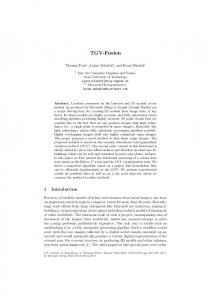
explore ways in which concepts and techniques used in one approach can be used to extend and enhance the modeling concepts and techniques used in the other. The intent is to establish a converging development path for Fusion and Syntropy that will yield a method (or methods) that embody sound, and well-defined OO modeling concepts and techniques that support the creation of expressive, precise, analyzable, and clear models. The most immediate differences between Fusion and Syntropy are at an apparently superficial syntactic level. For example, Fusion uses a filled inheritance triangle to express that a collection of subclasses are a complete partition of a superclass (i.e., that the superclass is abstract), whilst Syntropy uses a textual invariant of this fact in the superclass. The Syntropy notation however provides the possibility of distinguishing independent from dependent subclassing, i.e., whether the subtypes are possibly overlapping in their members or not (see Figure 1 – notice that the Fusion notation does not separate out the cases of disjoint non-exhaustive and non-disjoint exhaustive subtypes). However, these syntactic differences conceal Non-disjoint, non-exhaustive Subtypes: A
Non-disjoint, exhaustive subtypes: A
Non disjoint or non-exhaustive subtypes: A
invariants: abstract
B
C
B
B
C
Disjoint, non-exhaustive subtypes: A
C
Disjoint, exhaustive subtypes:
Disjoint, exhaustive subtypes:
A
A
invariants: abstract
B
B
C
B
C
C
Figure1: Notations for Subtyping in Syntropy and Fusion
more fundamental philosophical distinctions and emphases in the two methods. In this paper we attempt to identify more clearly the differences in the methods, and identify some ways that they can be usefully combined and enhanced with new notations. In Section 2 we give an overview of the Fusion and Syntropy methods. Section 3 gives an overview of the differences, and Sections 4 and 5 more closely compare and analyze the differences between the techniques used by Fusion and Syntropy in the analysis and design phases (respectively) of the development process. We conclude in Section 5 with a summary of our findings and with suggestions on how Fusion and Syntropy can beneficially influence each other.
07:58 2nd December 1997 — Object Oriented Systems — newfus
4
K. Lano, R. France, J-M. Bruel
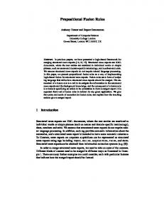
2 Overview of Fusion and Syntropy 2.1 Fusion Fusion [Coleman et al., 1994] aims to synthesise the best elements of OMT, Booch, CRC and formal methods, in order to provide a rigorous and well-defined method for object-oriented development. The method covers the analysis, and design phases of development, and provides guidelines for transforming OO designs to code. Although the models have, in principle, a rigorous semantic underpinning, the use of informal (natural) language to describe functionality and object state constraints, and the lack of a firm basis for establishing the consistency of models across the development phases can undermine attempts at using the method in a rigorous manner. An overview of the Fusion development process is shown in Figure 2. At the analysis phase, emphasis Requirements Document Analysis Interface Model
Object Model Domain
Op. Schema
System
Life Cycles
Design Object Interaction Graphs
Class Descriptions
Visibility Graphs
Inheritance Graphs
Scenarios
D A T A D I C T I O N A R Y
Implementation Program
Figure2: Fusion Process Model
is placed on identifying problem-oriented classes and their relationships (modelled by the Object Model) and specifying the externally observable effects of operations (described by the Operation Schemas and Lifecycle model of the Interface Model). A data dictionary records constraints and assumptions about the data which cannot be conveniently expressed in the Object Model. As with most object-oriented methods, the Object Model has the prime role in development, and serves as an input to the construction of design models. In Fusion, design involves
� � �
determining how instances of classes interact in order to accomplish the goals of the operations specified in the Interface Model (modelled by Object Interaction Graphs (OIGs)), determining how object instances refer to each other (modelled by Visibility Graphs (VGs)), consolidating design decisions by defining class structures and inheritance hierarchies that are suitable for implementation.
07:58 2nd December 1997 — Object Oriented Systems — newfus
A Semantic Comparison of Fusion and Syntropy
5
The Fusion modeling techniques are geared to the modeling of sequential, non-distributed systems; there is very little support for the modeling of concurrent and distributed behavior. The Octopus method [Awad et al., 1996] is an example of a method that extends Fusion’s notation to support the modeling of real-time, concurrent systems.
2.2 Syntropy Syntropy [Cook and Daniels, 1994] is a cohesive set of object-oriented modeling techniques based on OMT, with additional formal specification elements derived from Z. Three separate levels of modeling are used in Syntropy:
� � �
essential models, which model the problem domain of the new application; specification models, which abstractly model the requirements of the application; implementation models, which model in detail the required software.
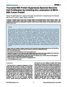
Class diagrams (similar to OMT object models) and statecharts are used at each of these levels. Additionally, object interaction graphs (termed mechanisms in Syntropy) are used at the implementation level, and type views are enhanced by visibility annotations and synchronisation specifications. Although a detailed process for Syntropy development is not given in [Cook and Daniels, 1994], by examining examples we can derive an informal flow of information through the Syntropy models and views as shown in Figure 3. The usual concept of “analysis” fits both aspects of the essential model (analysis of Essential Model Type View
State View
Specification Model Type View
State View
Implementation Model Type View
Mechanisms
State View
Figure3: Syntropy Process Model
the environment and domain of the system) and the specification model (analysis of the required system functionality and behaviour). Likewise the concept of design is involved in both the specification model (design of statecharts and interactions between them in order to achieve required responses to external events) and the implementation model (algorithm construction, transformation of event generation into message-passing, etc.). Clearly, in comparison with Fusion, its process model is less precisely defined, although as [Cook and Daniels, 1994] points out, in reality a method may be of more value as a collection of useful techniques rather than as a rigid step-by-step process.
07:58 2nd December 1997 — Object Oriented Systems — newfus
6
K. Lano, R. France, J-M. Bruel
3 Differences Between Fusion and Syntropy Models: An overview There are a number of technical and philosophical differences between the Fusion and Syntropy OO notations and techniques. Some of the more obvious differences are given below:
�
The following Fusion analysis models are absent from Syntropy: 1. Operation schemata and lifecycles: replaced in Syntropy by state views at the essential and specification model levels – the effect of an operation (i.e., the detection of an external event) is described in Syntropy by showing the effect on each class of objects separately, whilst in Fusion the effects are described in a single textual schema. Statecharts as used in Syntropy can express, in a somewhat indirect manner, the allowed or possible lifecycles for an object that are expressed using regular expressions in Fusion. 2. Scenarios: in Syntropy these are less emphasised at the essential model level, although they are used in constructing the specification model statecharts. Instead, events are discovered by examining the way elements of the type view may be modified, in addition to checking the external events. Event tables are then constructed as a step towards statechart construction, which are the definitive notation for representing event sequencing and validity in Syntropy. 3. Data dictionary: this information is maintained in Syntropy type views primarily. This means it must be duplicated on the three separate models, rather than being given as a separate model. The Syntropy approach is clearer however, if the details of data definitions change significantly from analysis to design and implementation.
� �
The type views of Syntropy essential and specification models correspond to the Fusion domain and system object models, respectively. At the analysis level in both notations, methods are not allocated to classes. The following differences between the set of models are present at the design and implementation levels: 1. Class descriptions are not constructed explicitly in Syntropy, whilst they are in Fusion. 2. Fusion proceeds further towards an executable system than Syntropy, providing guidelines for implementation in specific programming languages, which Syntropy avoids, defining instead an implementation-language independent physical design. 3. Syntropy considers concurrency constraints and mechanisms for the safe use of concurrent execution of threads through a set of objects, which Fusion does not. Fusion has however been extended to concurrent systems in the Octopus method [Awad et al., 1996].
In the following sections we examine the differences between Fusion and Syntropy more closely in order to uncover key philosophical and technical differences that can help determine how each method can benefit from the other.
4 Comparing Fusion and Syntropy Analysis Techniques In this section we compare and analyze the differences between Fusion and Syntropy analysis techniques, and suggest some useful extensions to both techniques.
07:58 2nd December 1997 — Object Oriented Systems — newfus
A Semantic Comparison of Fusion and Syntropy
7
4.1 Object Models and Type Views The aim of both the Fusion and Syntropy analysis level object models/type views is to describe abstractly the entities and relationships involved in a system, and to present them in a way that is relatively free of design or implementation expectations. In both cases, entities are presented without defining methods or operations which are local to these entities, so that design choices can be freely made about the partitioning of functionality between classes and the localisation of responsibilities into classes. Syntropy goes further than Fusion in attempting to abstract from a commitment to particular classes and data items, and avoids the terms “class” or “attribute”, preferring “type” and “property” (which includes parameterised enquiries) respectively. As in OMT and most other object-oriented analysis and design methods, object-valued attributes are not allowed at the analysis level of either method, but are instead represented by associations. Although both Fusion and Syntropy derive from the OMT notation for classes and associations, there are some significant differences in their notation and in the underlying techniques. Some of these differences are listed below: 1. Aggregates in Fusion can include associations and other diagram features, in addition to classes; 2. Fusion avoids mathematical notation for constraints between diagram elements where possible. Furthermore, expressing constraints such as “an association is a subset of another” or “an association has an element-like relationship to another” is problematic in Fusion, but more conveniently handled in Syntropy. 3. Syntropy supports navigation expressions, whereby constraints can be expressed between data items local to different classes within a domain in a system. Links between data in different domains are also possible, but are discouraged. Both Fusion and Syntropy support the modeling of ternary (and higher) associations and they both encourage breaking down such complex associations to simpler binary associations. Fusion uses the aggregate structure to reduce higher-order associations to binary associations, while Syntropy uses class representations of associations (treating associations as classes is not explicitly supported in Fusion). In general the emphasis on formal notation in the object model is much greater in Syntropy than in Fusion: Fusion attempts to express concepts rigorously through structured English, but the results are often not precise enough to support rigorous analysis at the semantic level.
4.1.1 Aggregation The greater emphasis on aggregation in Fusion leads to a quite distinct notation, whereby the classes and associations that are contained in the aggregate are textually enclosed in the class that contains them or is the “master” of the aggregation. In Fusion, parts (components) of an aggregate are not ‘owned’ by the aggregate. That is, a part instance in a Fusion aggregate instance may also be a part instance of another distinct aggregate instance. Fusion aggregation is not restricted to modeling only physical parts-of relationships. In fact, aggregation is described as a structuring mechanism in the Fusion text (see page 18, Sec 2-2.3 in [Coleman et al., 1994]). Lifetime binding of components and aggregates is handled at the design stage through Visibility Graphs, thus full modeling of physical parts-of relationships, where the lifetime of a component is included in the lifetime of its aggregate, is realized at design. Aggregations in Fusion are similar to relationships in that they are interpreted as tuples of instances. Aggregations enclosing relationships allows one to treat relationships as classes (i.e., they can have attributes and can be associated with other classes). In fact, Fusion aggregates that encapsulate a relationship are analogous to Syntropy association classes.
07:58 2nd December 1997 — Object Oriented Systems — newfus
8
K. Lano, R. France, J-M. Bruel An example that illustrates the Fusion aggregation notation is given in Figure 4. Here the entity
Aggregate
Aggregate att1 1
1
Part1
Part2 att3
att2
R
Figure4: Fusion Aggregation Example
Part
Part att
R Aggregate Part R Part
1 and 2 and the association . has its own attribute is an aggregate of the entities 1 whilst the other entities have attributes 2 and 3 respectively. The annotation 1 on the en1 object and exactly one 2 object in each closed class boxes indicates that there is exactly one (the number can be omitted in this case, as cardinality 1 is the default). is a 1-1 association between 1 and 2, and, because it is within the aggregate, the 1 object contained in a particular aggregate must be related via to the 2 object of this same aggregate. This constraint would be expressed in Syntropy via some additional mathematics, which the Fusion notation avoids (Figure 5). In Syntropy, the parts of an aggregate are ‘owned’ by the aggregate. Syntropy’s aggregation construct is oriented towards modeling only physical parts-of relationships. The parts of a Syntropy aggregate can be viewed as permanent attachments to the aggregate; their removal results in the part being destroyed. The destruction of the aggregate also implies the destruction of its parts. Unlike the Fusion approach, a conscious effort was made to make the aggregate relationship different from any other type of relationship in Syntropy. In Fusion, the aggregate is used as a structuring mechanism and modeling of physical parts-of relationships is not emphasised (at the analysis stage). In order to express the concept modelled by the Fusion model in Figure 4 in Syntropy, we need to make explicit the lifetime binding of parts and aggregate in the Fusion model, and we need two explicit additional associations to represent the aggregation of the two part entities in the aggregate, and an invariant which states the relationship between these three associations. Let us assume that the Fusion model has the following intended lifetime binding: the lifetime of the aggregate is included in the lifetime of the parts (i.e., destruction of a part results in the destruction of the whole, but the destruction of the whole does not necessarily imply destruction of the parts). The Syntropy model is shown in Figure 5. Syntropy gives a precise mathematical meaning to aggregation associations; that the lifetime of each part of an aggregate is contained within the lifetime of the (collection or object) at the “whole” end of the association (decorated with a diamond). Fusion defers lifetime considerations to the design stage, but outside of the lifetime considerations there are some holes in the Fusion interpretation of aggregation. The result is that some aggregate structures in Fusion are ambiguous (see Figure 6 and [Bruel et al., 1996] for more examples), specifically, those that involve associations that cross the aggregate boundary box and reenter the aggregate at another point (this can be used to model associations across aggregate instances,
att Aggregate Part
Part
R
Part
att Part
07:58 2nd December 1997 — Object Oriented Systems — newfus
A Semantic Comparison of Fusion and Syntropy Aggregate
9
Part1 att2
att1
R
Invariants: part1.part2 = part2
Part2 att3
Figure5: Syntropy Aggregation Example
but it is not explicitly discussed or defined in Fusion), and those that involve components in generalization/specialization hierarchies (see [Eckert, 1996]). Guidance Advisor
1
*
Student
assigned_to
Figure6: An ambiguous Fusion model
Semantically, a Fusion aggregate class denotes a set of objects, where “each object corresponds to a set of tuples”, where the tuples “are objects of the classes within the aggregate” ([Coleman et al., 1994], C-2, pg 267). The term “corresponds” may mean that: 1. there is a relationship defined between an aggregate object and its component objects, or 2. it may mean that an aggregate object is a set of tuples containing component objects. Interpretation 1 seems closer to the intuitive notion of aggregation as a structuring mechanism; the second interpretation abstracts out attributes of an aggregate (not including attributes of the parts) and so gives only a partial view of a Fusion aggregate. For example, using the second interpretation, an instance of in Figure 4 is effectively a pair ( 1; 2), where 1 2 1 and 2 2 2. denotes the set of existing objects of class . The symmetry of the Syntropy notation for aggregation is perhaps counter-intuitive (even the case study [Cook and Daniels, 1996] refers to a class being “enclosed” in another in order to express an aggregation), but it provides greater expressiveness. This is the case when there may be many containers that contain a given part (Figure 7). There is no way in Fusion object models to distinguish this situation from one where there is a unique container for each part. Admittedly, such a situation is rather unusual (a company must be associated with a given set of divisions on its creation, and this set cannot change during the lifetime of the company – a division might also migrate from one company to another once the first company had died).
Aggregate
C
p p
p
Part
07:58 2nd December 1997 — Object Oriented Systems — newfus
p
Part C
agg
10
K. Lano, R. France, J-M. Bruel
Company
Division
Figure7: Syntropy Multiple Aggregation
Aggregation in Fusion can be seen also as a form of inheritance: there are embeddings from the sets of objects of the container class to the sets of objects of each of the part classes (in the semantics, this is simply projection of a tuple onto one of its members). This is just how inheritance is modelled in Syntropy, so that a Fusion aggregate can be regarded as a multiple inheritance of its component classes, as in the VDM++ concept of indexed inheritance [Lano, 1995]. We discuss extensions of the Fusion aggregation concept to cover subsystem specifications in Section 4.4 below.
4.2 Associations Fusion notation for object models also differs from Syntropy and OMT notation in its approach to identifying the cardinality of an association, and in distinguishing optional and total associations. In Fusion, a relationship symbol drawn between two classes indicates the possibility that a relationship between two classes exists ([Coleman et al., 1994], pg. 15). In other words, a relationship is optional unless it is explicitly made mandatory. Fusion uses a “totality” marker (a black square) on an association to indicate that the adjacent end of the association is mandatory. As [Eckert, 1996] points out, Fusion allows the use of both 0 cardinalities and totality markers, which can lead to some confusion over interpretation of relations, and leads to the possibility of multiple, quite visually distinct, presentations of the same mathematical concept. In Syntropy, optional and mandatory relationships are defined solely in terms of cardinalities (where a cardinality with a lower range of 0 indicates optional relationships, and cardinalities with greater than 0 lower ranges indicate mandatory relationships). This approach is much cleaner than the Fusion approach, and is more likely to produce relationships that require less effort to interpret. We propose therefore that any combined Fusion/Syntropy method should adopt the standard OMT and Syntropy notation for association cardinalities. Fusion seems to be heading towards the adoption of the more standard notation for relationships: the authors of Fusion recently announced [Malan, 1996] that they would adopt the Unified Modeling Language (UML) [Booch and Rumbaugh, 1997].
4.2.1 Specifying constraints Invariant constraints in classes are another useful feature of Syntropy, although if used to excess they can obscure a diagram. A particular additional use for these would be to specify the allowed number of objects of a class, i.e., how many objects of this class may exist at any given time. Using the formal semantics developed in the appendix, this amounts to placing constraints on the value # – the cardinality of the set of existing objects of . In Fusion constraints are expressed as textual annotations in an Object Model. Unlike Syntropy, Fusion does not explicitly support formal expression of constraints.
C
C
07:58 2nd December 1997 — Object Oriented Systems — newfus
C
A Semantic Comparison of Fusion and Syntropy
11
4.2.2 Transition from Domain Modeling to System Modeling In Fusion the transition from the object model which describes the domain to the model that describes the system itself is carried out by drawing a system boundary which is a line forming a closed curve which separates those classes and associations that are part of the intended system from those that belong to its external environment. Syntropy does not follow such a simple, precise technique for transforming a type view in an essential model into a specification model type view. Instead, more complex derivations are allowed. The explicit construction of the system boundary in Fusion allows, however, a distinction that is not made in Syntropy. This is the possibility of an entity being presented in two places, both inside the boundary (to represent the data that the system must hold about the entity) and outside (to represent the role of that entity as an agent that communicates with the system). In many cases, particularly for reactive systems, the simple approach of drawing a system boundary is not sufficient: the classes that reside in the system and record information about the external agents need not have a direct relationship to these agents, or may discard or adjoin new attributes and properties [Awad et al., 1996, Eckert, 1996]. Thus the Syntropy approach seems the more realistic in general, although insufficient guidelines for the essential to specification model transformation are given in [Cook and Daniels, 1994]. In Syntropy, the semantics of statecharts undergoes a significant change from the essential to the specification models. Transition guards in essential model statecharts have the usual interpretation that if they fail to be true, then the transition cannot take place. In the specification model, they mean instead that if the transition occurs outside of this guard, then nothing is known about its effect{ . It could be argued that both guarding and preconditioning need to be modelled at the specification stage (and indeed, the consideration of concurrency issues leads Syntropy to reintroduce guards at the implementation level, but expresses them on the object model). Guards (as blocking guards) give information on what transitions are not permitted, whilst preconditions identify what permitted transitions need to be handled in the software.
4.3 Interface Models and State Views Fusion interface models are split into operation schemas and lifecycles (scenarios are also used to help derive the schemas and lifecycles), whilst Syntropy uses a unified statechart notation which, in principle, subsumes each of these. Lifecycles identify legitimate sequences of behaviour for a system – events that happen out of sequence are ignored, as with “allowed” events in Syntropy. The problem with separate notations is that they must be kept consistent with each other. The advantage is that they enable consistency checking and allow the presentation of simplified aspects of the interface model.
4.3.1 Operation Schemas Versus Statecharts Syntropy statecharts consist of a set of states, possibly with nested substates, and transitions between states. Transitions are labelled with the name of the event which triggers their occurrence, together with a precondition, postcondition, and a filter predicate. Labels are of the form ( [ ])[ ]=[ ] where is the event name, is a list of object or value parameters and is a filter identifying which events the object should react to. is the precondition (or guard) and is the postcondition. If the filter is true for a particular object, then this object must respond to by following some transition for (which one is
p
Pre
e
f Post
e p f Pre Post
e self
e
{ This means that there can be many spurious transitions implicitly present: for each event e, from each state not currently the source
of a transition for e to any other state in the statechart.
07:58 2nd December 1997 — Object Oriented Systems — newfus
12
K. Lano, R. France, J-M. Bruel
determined by which precondition is true), if the filter is false, the object ignores the event (remains in the same state). Parts of the labelling which apply to all transitions for , such as the filter and parameter typing, are usually placed in the event list. For example, in Figure 8 the event has a transition labelled ( [ ])[ = ] from to : in this case every object of must respond to the event ( ): itself will follow this particular transition for the event, other objects will follow the self-transition for the state . Fusion operation schemas are a more abstract form of operation description, which give the global effect of an operation, listing the data read and changed, messages sent, preconditions ( clause) and postconditions ( clause). All these clauses are usually described using structured natural language. Figure 13 gives an example operation schema using mathematical notation for these items. Unlike postconditions in Syntropy specification model statecharts, a Fusion operation schema for an operation describes a complete set of responses to the external event that triggers the operation. In Syntropy this response could consist of many intermediate steps involving internal communication within the system. This corresponds to the distinction between internal computation steps and external reaction cycles in the synchronous real-time paradigm [Lann, 1992]. An operation schema in Fusion describes the entire reaction to an event, whilst specification model statecharts in Syntropy describe the internal steps that make up this reaction. In addition, Fusion operation schemas do not imply a localisation of functional aspects to particular classes, as statecharts often do. The effects of an operation are described in a global manner, thus leaving open more possibilities for design choices than the Syntropy approach. Statecharts inevitably impose some design choices, particularly when internal events are used to express a chain of internal system responses and processing steps leading to some eventual external response to an external input. Unlike Fusion operation schemas, the list of read but not written data of an operation or transition are not explicitly given in Syntropy, nor are the list of changed data. The conflict between the local specification aspects of statecharts and the concern in Syntropy to abstractly express global state transformations that are consequences of events can lead to obscure and convoluted specifications. For example, the petrol station case study [Cook and Daniels, 1996] features events whose filters, preconditions and postconditions require navigation across up to four classes in the model, and collaboration between separately specified behaviour for these classes. Filters are also used which rely on dynamic associations, contrary to the restrictions of [Cook and Daniels, 1994]. The radio button example of [Cook and Daniels, 1994] highlights the lack of clarity which can arise as a result of enforced local (to objects) behaviour specification. The Syntropy statechart in this case is shown filter in the event list indicates that every existing object of may in Figure 8. The react to the event. The way in which they react depends upon whether they are the button being pressed ( = ) and what their current state is. However the global (at the level of the class) effect of the ( ) event is simply:
e
turn on x true x self O� On turn on b b O�
turn on
Result
true turn on x self turn on x On = f x g O� = RadioButton n f x g
RadioButton Assumes
RadioButton RadioButton
which is a more abstract, clear and design-free description than that given by the statechart. The Syntropy approach has other problems, notably an asymmetry in handling changes to associations: one or other of the entities can have responsibility for modifying the association (as viewed from its end), and can regard the change to the inverse association as being implicitly included in the effect. This is less clear than the Fusion approach which explicitly modifies the association as a global data item.
07:58 2nd December 1997 — Object Oriented Systems — newfus
A Semantic Comparison of Fusion and Syntropy
13
RadioButton turn_on(x)[x /= self]
turn_on(x)[x = self]
Off
turn_on(x)[x /= self]
On
turn_on(x)[x = self] Events: turn_on(x: RadioButton [true])
Figure8: Statechart of Radio Button
In these respects the Fusion interface model is more abstract than the Syntropy state view. Various inadequacies exist in the Fusion approach however because of its relative lack of formality. In particular, changes to association attributes which may be required as a result of an operation are not considered in [Coleman et al., 1994, page 26], nor are deletion of objects. Both can be treated in Syntropy, although the or action for objects, dual to , is also a problem in this method. Aglack of an explicit gregates are not treated as modifiable items within Fusion operation schemes [Eckert, 1996], whilst they can be modified, subject to the aggregation constraints, within Syntropy.
delete kill
new
4.4 Useful extensions to Fusion and Syntropy analysis techniques 4.4.1 Context diagrams An important additional model that is not officially part of either Syntropy or Fusion is a Context Diagram (or level 0 Control and Data Flow Diagram in the sense of [Mellor and Ward, 1985]). These diagrams show the flow of events and data between external agents and the system, and can be used to give an overview of interactions. For example, in the petrol station case study of [Cook and Daniels, 1996] we could express the overall architecture as in Figure 9 (event parameters could also be added). This diagram makes it clear that there will need to be special facilities for the manager of the petrol station that are not available to the attendants (changing the price of a grade of petrol might also belong to the managers interface, rather than to the attendants, but the requirements do not consider this). Such models would help overcome some of the conceptual misunderstandings experienced by users of Fusion described in [Eckert, 1996]. Another useful additional notation in the case of Syntropy would be control and data-flow diagrams of the SA/RT method [Mellor and Ward, 1985]. These could be used to summarise the strategy for internal communication taken in a system. For instance, the diagram for the share monitoring system is given in Figure 10. Solid lines indicate a flow of data, whilst dashed lines indicate a flow of events. Classes are
07:58 2nd December 1997 — Object Oriented Systems — newfus
14
K. Lano, R. France, J-M. Bruel
Pump
Clock
Manager
alarmOff alarmOn motorOff motorOn pumpUpdate
endOfPeriod
dispensePulse gunRemove gunReplace
hire fire reprintRequest
receiptPrint reportPrint
System
levelChange
Printer consoleUpdate
activate cancel pay setPrice terminate
Tank
Attendant / Console Figure9: Context Diagram of Petrol Station
Information Service
priceChange System
Share
priceCheck movement
Minder minderAlarm
Alarmstore
Figure10: Control and Data Flow Diagram for Share Monitoring
07:58 2nd December 1997 — Object Oriented Systems — newfus
A Semantic Comparison of Fusion and Syntropy
15
represented as transformers of event flows when their behaviour is defined by statecharts, following SA/RT conventions. A more complex example is the processing of the petrol station management system of [Cook and Daniels, 1996]. This has the (partial) data and control-flow diagram shown in Figure 11. Such diagrams can help hire
fire
pumpUpdate
endOfPeriod
gunReplace dispensePulse
Attendant
Pump Reporting Period
Petrol Station levelOK
Transaction Grade
Tank
costPerLitre levelChange
setPrice
consoleUpdate receiptPrint
Figure11: Control and Data Flow Diagram for Petrol Station
guide the construction of the object interaction graphs, and provide a global view of the dependencies between classes involved in constructing responses to particular events. These more detailed CDFDs can be checked for consistency with the context diagram by ensuring that each event or data flow into or out of the system in the more detailed diagram coincides with such a flow in the context diagram. Here this is the case since the flow is from the (external) agent to its internal representation in the system, and likewise for the flows into and out of . The originate from the agent, and the flow comes from the flows into . The flows and are between the and the system, and the flow goes to the . Likewise we should check that each flow in the context diagram is also represented in the more detailed diagram.
levelChange Attendant Manager endOfPeriod Clock setPrice consoleUpdate Console receiptPrint Printer
Tank Pump
4.4.2 Formalising Operation Schemas Fusion operation schemas can be enhanced by the use of mathematical expressions for pre and post-conditions. In particular, we can systematically map Syntropy state views to a semantically equivalent Fusion-style operation schema:
07:58 2nd December 1997 — Object Oriented Systems — newfus
16
K. Lano, R. France, J-M. Bruel
e
1. For each external event that is detected by the system, examine each of the statecharts of entities in the system that respond to , and incorporate the effects of defined on these statecharts into the postcondition of on the operation schema. The preconditions of transitions caused by are combined together to give the precondition of the operation schema. However each separate case represented by the different transitions needs to be reflected in the postcondition. For example, if entity can respond to if holds to yield an effect , and can respond to if : holds to yield an effect , then the derived operation schema has precondition but postcondition
e
G
C
e
e
Q
e
e G
P
true
e
old G ) P and old not(G) ) Q where old R denotes that R held at commencement of the operation. Alternatively, these separate cases can be described in distinct operation schemas for the same operation, with preconditions G and not(G) respectively, and postconditions P and Q respectively. 2. For specification models, a number of internal events and subsequent responses may result from detection of e, and all the effects of these internal steps should be incorporated into the single pre/post description of the Fusion operation schema for e. The following example shows how this can be carried out in practice. 3. Parameters of e and data that is only accessed and not changed by the pre and postconditions of its transitions become input data of the operation schema(s) for e. Output and modified data, including created objects, are listed in the Changes part of the operation schema(s). Objects that are created are prefixed by “new” in this list. 4. External events generated from the transitions of e are listed in the Sends list. The formal semantics for Syntropy given in [Lano, 1996] can be used as the basis for the translation, and would produce fully formal Fusion operation schemas. The above process is illustrated in Figure 13 which gives the operation schema of the processing required by a event in the share monitoring example of [Cook and Daniels, 1994] (Figure 12). Here we assume that an external agent receives the alarms raised by the minders of a given share. Notice that we have included the extents and of the two subtypes of in the list of (global) data which is changed by the operation. This is because the operation may move from the set to the set. Likewise for and , although in this case it is more difficult to express exactly how these sets change:
priceChange
Unpriced
Priced
alarmstore Priced Unpriced Armed Triggered
Armed = old Armed n T [ A Triggered = old Triggered [ T n A where T is the set fm 2 Minder j m:minded = s ^ s:movement > m:limitg
Share s
s
of minders which have been triggered by the present movement on the share , and
fm 2 Minder j m:minded = s ^ s:movement � m:limitg
s
A is the set
of minders which have been deactivated by the present movement on the share . This approach unifies the semantic expression of object creation and deletion and the movement of an object from one state to another.
07:58 2nd December 1997 — Object Oriented Systems — newfus
A Semantic Comparison of Fusion and Syntropy Monitor:
deactivate
Armed
Alarmed
alarm
deactivate
alarm
(p,b,mon)/[price’ = p] [bound’ = b] [monitor’ = mon] Unpriced
17
Share priceChange(v)/ [price’ = price + v]
Priced
priceChange(v)[abs(v) >= bound]/ [price’ = price + v] alarm(monitor)
priceChange(v)[abs(v) < bound]/ [price’ = price + v]
Figure12: Statecharts of Monitor and Share
minderAlarm
The sending of the signals is described by using these events as terms meaning “the event happens” (in the interval during which the global operation occurs). In terms of the semantics given “calls” a in the appendix this is equivalent to requiring that the (response to) action in the case that a minder limit is exceeded for the share. We can use the simpler formulation in terms of ) here instead of � because the Fusion interface model assumes that all actions are non-overlapping: the history of the system is a linear discrete sequence of intervals in which one or more actions (input or output) occurs. Notice that this operation model abstracts away from the intermediate events which are needed in the Syntropy model. Consistency checks performed in Fusion can be applied in Syntropy, i.e., that every entity on the type view is used in some event processing, and that the entities used in event processing are present on the type view. In addition, we can check that transitions establish the invariants of their target states (corresponding to the Fusion check that operation schema pre and postconditionsare consistent with lifecycle expressions).
priceChange
minderAlarm
priceCheck
4.4.3 Subsystem Specifications A deficiency of both Fusion and Syntropy is the lack of a general means for specifying subsystems: groups of classes, associations and other diagram elements which are closely semantically linked. The Fusion aggregation concept provides a partial means for such specification, allowing local attributes to be attached to a subsystem (aggregate) and constraints on associations to be expressed. However it does not provide for general operation specifications or formal constraints to be defined. Syntropy provides no level of structuring between individual classes and entire systems (or domains) – constraints between associations and between attributes of different classes are expressed via navigation expressions and invariants which are
07:58 2nd December 1997 — Object Oriented Systems — newfus
18
K. Lano, R. France, J-M. Bruel
priceChange
Operation: Description: A given share has its price modified at a particular date and time. Reads: supplied : supplied : supplied : supplied : : of Changes: of of of new :
s Share p Number d Date t Time limit Number Monitor price s shareChange s movement s sc ShareChange Priced Unpriced Armed Triggered
Sends:
alarmstore : fminderAlarm(m) j m 2 s minderg s 2 Share The share exists Result: sc = newShareChange (p d t) s price = p s 2 old Priced ) s movement = old s movement + p ? old s price s shareChange = old s shareChange a [sc] Priced = old Priced [ fsg Unpriced = old Unpriced n fsg m 2 Minder ^ m minded = s ) m 2 old Armed ^ s movement m limit ) m 2 Triggered ^ minderAlarm(m) m 2 old Triggered ^ s movement � m limit ) m 2 Armed Figure13: Operation Schema for priceChange :
Assumes:
;
;
:
:
:
:
:
:
:
:
>
:
:
:
07:58 2nd December 1997 — Object Oriented Systems — newfus
A Semantic Comparison of Fusion and Syntropy
19
local to particular classes. Such localisation may be arbitrary (the expressions and invariants could just as well be written in other classes) and may therefore reduce the clarity and abstraction of the specifications concerned. For example, consider Figure 14. Here there are two alternative ways of expressing the constraint that external_students
external_at
Student
College taught_at
teaches
lives_at
accomodates
Figure14: Subsystem Example
every student taught by a college is either an external student or lives at the college. As an invariant of
College we could write: teaches � accomodates [ external students As an invariant of Student we could alternatively express it as: external at = taught at _ lives at = taught at
Subset constraints could also be used between associations. However a more abstract treatment of the situation would use a “Tuition” subsystem and a constraint, at the level of this subsystem, involving the associations (Figure 15). can be regarded as a class with attributes and , the sets of existing students and colleges, and attributes
Tuition
Student
College
external study : College $ Student teaching : College $ Student accomodation : College $ Student representing the current value of the associations concerned. The local invariants of the classes can be deduced from this more global model. Operations that change associations would also be most naturally specified at the level of a subsystem which includes the association and the classes it connects. Thus we could envisage the use of Fusion operation schemas at the subsystem level, in addition to the global system level: this would support the principle that we should specify operations as locally as possible, without compromising comprehensibility, but not more locally.
5 A Comparison of Fusion and Syntropy Design Techniques In this section we compare the techniques used by Fusion and Syntropy to model designs.
07:58 2nd December 1997 — Object Oriented Systems — newfus
20
K. Lano, R. France, J-M. Bruel Tuition external_study
Student
College teaching
accomodation
Invariants: teaching
accomodation
external_study
Figure15: Subsystem Example – Extended Notation
5.1 Interaction Graphs Whilst both Syntropy and Fusion use the interaction graph notation at the design and implementation level, they differ both in the use of this notation and in how interaction graphs are derived from earlier lifecycle notations. Syntropy interaction graphs (termed “mechanisms”) do not use dashed rectangles to represent object collections – such collections defer consideration of iteration orders, which Syntropy considers explicitly at this stage via statecharts. In Syntropy the construction of interaction graphs is based on an analysis of the event responses and sequencing expressed in statecharts. External events that the system responds to become updater methods of one of the classes that responds to them (or a new “master” class which coordinates the reaction is invented to hold this method). If several objects can respond to a given event, then a structure for the communication pattern between the involved objects needs to be determined, yielding an order for the message sends in the interaction graph for this event. In contrast, Fusion bases interaction graphs on navigation requirements for implementing a particular operation, and invents a controller object to supervise the interaction that will achieve its functionality. Controller objects are often already recognised by Syntropy as those objects which directly respond to an external event, rather than to internal events generated from this event.
5.2 Domains In Syntropy an important step in deriving an implementation type view is to divide the system into several domains or subsystems, each of which may act as an “environment” for other domains. For example, a domain may contain classes which hold the core conceptual representations of a system, such as kilns in a factory [Daniels, 1996], and regard other domains, such as a domain for kiln and other device controllers, as part of its environment. Both domains would fall into the system representation in Fusion. Typical domains are infrastructure domains concerning aspects such as persistence of objects in the system, and interaction domains concerning user and device interfacing. Reducing the dependencies between these
07:58 2nd December 1997 — Object Oriented Systems — newfus
A Semantic Comparison of Fusion and Syntropy
21
domains is an important part of the implementation process in Syntropy. Partitioning into domains is not explicitly considered in Fusion. Design patterns [Gamma et al., 1994] are used to an extent in Syntropy to achieve domain partitioning and restructuring, but could have far wider application in the construction of design and implementation structures, in both Fusion and Syntropy.
5.3 Visibility Graphs Fusion uses visibility graphs at the design level in an essential way in order to guide implementation choices. These graphs use interaction graph notation, and show what knowledge one object has of another, and whether this knowledge is temporary (dashed arrows) or permanent (solid arrows). They also distinguish exclusively owned and bound objects. In contrast, Syntropy annotates associations in a type view by arrows indicating the corresponding known access routes between objects of the classes involved in the association. This notation can make fewer distinctions than the Fusion notation (for example, it is possible that only certain objects of a particular class need access to objects of an associated class, and some transitory accesses could arise from parameter passing in messages, which are not captured on the type view).
6 Development Process Fusion adopts an orthodox separation between analysis as capturing what a system is intended to achieve, and design as defining how these requirements are to be met. In contrast Syntropy characterises analysis as concerned with discovering and describing those aspects of the software system about which there is no choice, whilst design is the creation and description of those aspects about which a choice exists. Thus, in principle, essential modeling could be used to support design as well as analysis, although, in practice, it is primarily used for analysis. Neither Fusion or Syntropy provide formal relationships or consistency checks between their analysis and design models. This is in contrast to the approach of formal methods such as VDM++ [Lano and Goldsack, 1996] which do give such criteria. Whilst formal proof of refinement is not usually economically practical at present, generation of proof obligations can be of assistance in a review process. Formalising the Fusion refinement steps may be more problematic, as there are more differences between the design and analysis notations used in Fusion than in Syntropy. In Syntropy, it would be, in principle, possible to relate the type views at the essential, specification and implementation levels via some form of theory interpretation of their corresponding theories, and similarly for the state views (interaction graphs are, strictly, supplementary to implementation state views). It is less clear to relate the different notations in Fusion, which has led to suggestions that some form of design object model is added to its model set [Ricketts, 1996].
7 Conclusions At a notational level, object-oriented analysis and design has produced three very effective techniques for describing the requirements and design of a system: 1. Object models; 2. Statecharts; 3. Object interaction graphs.
07:58 2nd December 1997 — Object Oriented Systems — newfus
22
K. Lano, R. France, J-M. Bruel
Each of these notations is able to convey significant parts of the structure and behaviour of a system. The Fusion and Syntropy methods have extended and enhanced these notations in a number of ways, and Syntropy object models represent the most precise form of this notation so far developed in an OO method. In contrast the Syntropy variant of statecharts, whilst improving on the standard (Statemate) notation in many ways, introduces excessive complexities when used at the implementation level to describe iterative or other complex functionality (pseudocode would be a better alternative), and in its lack of representation of both preconditions and guards. In addition, the concept of event validity, particularly when orthogonal statecharts are involved, is highly complex. The Fusion and Syntropy version of object interaction graphs are the most advanced version of this notation, with the Fusion version providing more detailed distinctions than the Syntropy version. Beyond this core of key notations, there are the following aspects of Fusion which may be of use as additional analysis and design tools for Syntropy:
� � � � � �
Operation schemes, possibly with formal mathematical notation based on that of Syntropy and its semantics; Lifecycles, as more concise and immediately comprehensible supplements to statecharts, or as replacements for statecharts in simple cases – this would also provide an additional validation check on the statechart descriptions; Class enclosure as a notation for many kinds of aggregation construction: tools should be able to convert from this representation into the Syntropy representation automatically; Collections of objects as nodes in interaction graphs; Visibility graphs at the level of detail given in Fusion; Class descriptions as a means of unifying the implementation-level information.
The following elements of Syntropy could be used to enhance Fusion:
� � � � � �
Statecharts, and the rules for statechart subtyping given in Chapter 8 of [Cook and Daniels, 1994]; Navigation expressions – these have been adopted in part in UML, for example [Booch and Rumbaugh, 1997]; Initial states of a system (described in Fusion by a operation schema with no precondition over the system variables); Distinctions between all four forms of subtyping described in the introduction; Orthodox notation for association cardinalities in place of Fusion “totality” markers, plus extensions of the aggregation notation to capture the multiplicity of the whole – Syntropy notation and semantics for aggregation has also been partly adopted in the Unified method; Consideration of domains, and the architectural issues arising from dependencies between domains.
The following aspects are not present in either method but could be consistently added:
� � � �
Context diagrams and more detailed control and data-flow diagrams; Subsystems and subsystem constraints – Fusion operation schemas could be attached to subsystems in addition to the entire system; The use of terms such as attributes from the semantics to provide more precise constraints on object creation and deletion and on the number of objects of a class which are permitted; The incorporation of design patterns as standard techniques for constructing implementations and designs.
C
07:58 2nd December 1997 — Object Oriented Systems — newfus
A Semantic Comparison of Fusion and Syntropy
23
In conclusion, the Fusion and Syntropy approaches to object-oriented modeling are based on different concerns and emphases. The Fusion approach focuses on practicality, and as such there is heavy emphasis on graphical models that present pertinent information in a concise, structured and understandable manner, and on a methodical approach to development. In Syntropy, the emphasis is on creating precise graphical models of systems that can be rigorously interpreted and analysed. Fusion and Syntropy are exemplary examples of object-oriented methods from the perspectives of practicality (Fusion) and rigor (Syntropy). These two perspectives are, for the most part, complementary. Fusion concepts can be the basis for enhancing the practical aspects of Syntropy, and Syntropy concepts can be the basis for providing a more rigorous base for the use of Fusion. This paper has shown how Fusion and Syntropy concepts can be used to enhance the modeling capability of each other. The improvements we have suggested here are relevant also to the UML, since aspects of Fusion and Syntropy have been adopted in this method.
References [Awad et al., 1996] M Awad, J Kuusela, and Jurgen Ziegler. Object-oriented Technology for Real-time Systems. Prentice Hall, 1996. [Banieqbal and Barringer, 1987] B Banieqbal and H Barringer. Temporal logic with fixed points. In Temporal Logic in Specification, volume 398 of Lecture Notes in Computer Science. Springer-Verlag, 1987. [Booch and Rumbaugh, 1997] G Booch and J Rumbaugh. UML Version 1.1 Language Description, Rational Software Corporation, Santa Clara, CA-95051, USA, October 1997. [Booch, 1994] G Booch. Object-oriented Design with Applications. Benjamin Cummings, 1994. [Bruel et al., 1996] J-M Bruel, R B France, B Chintapally, and G K Raghavan. A tool for rigorous analysis of object models. In Proceedings of the 20th International Conference on Technology of Object-Oriented Languages and Systems (TOOLS’96), 1996. [Coleman et al., 1994] D Coleman, P Arnold, S Bodoff, C Dollin, H Gilchrist, F Hayes, and P Jeremaes. Objectoriented Development: The FUSION Method. Prentice Hall Object-oriented Series, 1994. [Cook and Daniels, 1994] S Cook and J Daniels. Designing Object Systems: Object-Oriented Modelling with Syntropy. Prentice Hall, Sept 1994. [Cook and Daniels, 1996] S Cook and J Daniels. Syntropy Case Study: The Petrol Station. Technical report, Object Designers Ltd., 1996. [Daniels, 1996] J Daniels. Software Architecture with Syntropy (TOOLS ’96 Tutorial). Technical report, Object Designers Ltd., 1996. [Eckert, 1996] G Eckert. Improving the Analysis Stage of the Fusion Method. In Object-Oriented Development at Work – Fusion In the Real World, chapter 11. Prentice Hall, 1996. [Fiadeiro and Maibaum, 1991] J Fiadeiro and T Maibaum. Describing, structuring and implementing objects. In de Bakker et al., editor, Foundations of Object-Oriented languages, volume 489 of Lecture Notes in Computer Science. Springer-Verlag, 1991. [Fiadeiro and Maibaum, 1992] J Fiadeiro and T Maibaum. Temporal theories and modularisation units for concurrent system specification. Formal Aspects of Computing, 4(3):239–272, 1992. [Gamma et al., 1994] E Gamma, R Helm, R Johnson, and J Vlissides. Design Patterns: Elements of Reusable ObjectOriented Software. Addison Wesley, October 1994. [Jacobson, 1992] I Jacobson. Object oriented software engineering. Addison-Wesley, 1992. [Kent and Lano, 1995] S Kent and K Lano. Technical Report Axiomatic semantics for VDM++ . AFRO/IC/SKKL/SEM/V1, Dept. of Computing, Imperial College, August 1995. [Lann, 1992] G Le Lann. Designing real-time dependable distributed systems. Computer Communications, 15(4), 1992.
07:58 2nd December 1997 — Object Oriented Systems — newfus
24
K. Lano, R. France, J-M. Bruel
[Lano and Goldsack, 1996] K Lano and S Goldsack. Integrated formal and object-oriented methods: The VDM++ approach. In 2nd Methods Integration Workshop, Leeds. EWIC Series, Springer-Verlag, 1996. [Lano, 1995] K Lano. Formal Object-oriented Development. Springer-Verlag, 1995. [Lano, 1996] K Lano. Semantic Frameworks for Syntropy. Technical Report GR/K67311-1, Dept. of Computing, Imperial College, 1996. [Malan, 1996] R Malan. Fusion directions. Fusion Newsletter, 4(2):13, April 1996. [Mellor and Ward, 1985] S Mellor and P Ward. Structured Development for Real-time Systems (3 Volumes). Yourdon Press, 1985. [Pnueli, 1986] A Pnueli. Applications of temporal logic to the specification and verification of reactive systems: A survey of current trends. In J de Bakker, W P de Roever, and G Rozenberg, editors, Current Trends in Concurrency, volume 224 of Lecture Notes in Computer Science. Springer-Verlag, 1986. [Ricketts, 1996] H Ricketts. Proposed enhancements to the FUSION method. In Object-oriented Development at Work: The FUSION Method in the Real World. Prentice Hall, 1996. [Rumbaugh et al., 1991] J Rumbaugh, M Blaha, W Premerlani, F Eddy, and W Lorensen. Object-Oriented Modelling and Design. Prentice Hall, 1991. [Ryan et al., 1991] M Ryan, J Fiadeiro, and T S E Maibaum. Sharing actions and attributes in modal action logic. In T Ito and A Mayer, editors, Proceedings of International Conference on Theoretical Aspects of Computer Science (TACS ‘91). Springer-Verlag, 1991. [Wirfs-Brock and Wilkerson, 1989 ] R Wirfs-Brock and B Wilkerson. Designing object oriented software. PrenticeHall, 1989.
A: Semantic Framework for Syntropy In this appendix we describe a semantics developed for Syntropy in the “Formal Underpinnings of Object Technology” project. It makes use of an extension of the object calculus of [Fiadeiro and Maibaum, 1992] to cover durative and overlapping actions and composed actions. The report [Lano, 1996] gives full details of this semantics.
A:.1 The Object Calculus An object calculus theory consists of a set of type and constant symbols, attribute symbols (denoting timevarying data) action symbols (denoting atomic operations) and axioms describing the types of the attributes and the effects, permission constraints and other dynamic properties of the actions. The axioms are specified using linear temporal logic operators (next), U (strong until), (always in the future) and (sometime in the future). There is assumed to be a first moment. The predicate is true exactly at this time point. is also an expression constructor. If is an expression, denotes the value of in the next time interval. The version used here is that defined in [Kent and Lano, 1995] in order to give a semantics to VDM++ . In this version actions � are potentially durative and overlapping, with associated times !(�; ), "(�; ) and #(�; ) denoting respectively the times at which the -th invocation of � is requested, activates and terminates (where 2 N1). Modal operators } “holds at a time” and ~ “value at a time” are added: '} asserts that ' holds at , whilst ~ is the value of at time . In order to give a semantics to a class (for example, an OMT [Rumbaugh et al., 1991], Syntropy [Cook and Daniels, 1994] or VDM++ [Lano, 1995] class), we define a theory ?C which has the type symbol @
2
e
e
i
e t
3
BEG
e
i
i
i
e
t
t
C
07:58 2nd December 1997 — Object Oriented Systems — newfus
i
t
C
A Semantic Comparison of Fusion and Syntropy
C kill c
25
C
C c
representing all possible instances of , attribute symbol representing all the existing objects of , and creation C ( : @ ) and deletion C( : @ ) actions which respectively add and remove from this set. The attributes of a (class) type on a type view become represented as attributes of the corresponding modal theory, indexed by identifiers @ for instances of . Basic actions that modify these attributes are extracted from the statechart for . Each attribute of is formally represented by an attribute ( : @ ) of ?C (written as : for conformance with standard OO notation) and each action ( : ) is represented by an action symbol ( : @ ; : ), written as ! ( ). Output parameters of methods are also represented as attribute symbols of ?C . Statechart states of are represented as subtypes of . The theory of with its dynamic model extends each of these theories and adds actions which move elements from one state subtype to another (as required by transitions of the statechart) by deleting an element from the source subtype, and adding it to the target subtype. The theory of the dynamic model of also contains actions ! ( ) for each event that may be responded to by instances of . More than one instance of may respond, in the same interval, to this message, depending upon a filter predicate ( ) on the object . An additional attribute is included to represent the current global time. Notice that the explicit distinction between the type @ and the set makes clear the difference between an intensional and extensional view of classes. As [Eckert, 1996] argues, such a distinction is critically important, and is ignored to some extent in both Fusion and Syntropy. We can define the effect of actions by means of the “calling” operator � between actions:
new c
C
C
C C C C att C c att act c C x X C C
C
C now
� �
8 i:
C
c act x C
C
fa
att c act x X
ae x
e
a
C
C
�
N1 � now = "(�; i) ) 9 j : N1 � "( ; j) = "(�; i) ^ #( ; j) = #(�; i)
In other words: every invocation interval of � is also one of . This generalises the Object Calculus formula � ) to take account of the case where both actions are durative, and where may be composite. Composite actions are defined to represent specification statements and executable code, particularly the definitions of operations expressed in interaction graphs: names an action � with the following properties:
pre G post P 8 i : N1 � now = "(�; i) ) G}"(�; i) 8 i : N1 � now = "(�; i) ) P[att~"(�; i)=( att?]}#(�; i) In other words, G must be true at each invocation time "(�; i) of �, whilst P, with each “hooked” attribute ( att? interpreted as the value att~"(�; i) of att at initiation of �, holds at the corresponding termination time #(�; i). A frame axiom asserts that attributes of an object a of C can only be changed over intervals in which at least one of the actions a!m(e) of a executes [Fiadeiro and Maibaum, 1991]. ( ? Assignment t1 := t2 can be defined as the action pre true post t1 = t2 where t1 is an attribute symbol. Similarly sequential composition ; and parallel composition jj of actions can be expressed as derived combinators:
8 i:
N1 � 9 j; k : N1 � "(�; ; i) = "(�; j) ^ #(�; ; i) = #( ; k) ^ "( ; k) = #(�; j)
07:58 2nd December 1997 — Object Oriented Systems — newfus
26
K. Lano, R. France, J-M. Bruel
and
8 j; k : N1 � "( ; k) = #(�; j) ) 9 i : N1 � "(�; ; i) = "(�; j) ^ #(�; ; i) = #( ; k) The MAL [Ryan et al., 1991] operator [�]P is defined as: [�]P � 8 i : N1 � now = "(�; i) ) P[att~"(�; i)=( att?]}#(�; i) (? where each pre-state attribute att is replaced by the value att~"(�; i) of att at initiation of �. This operator provides a flexible way of specifying the effect of a method, transition or operation, by (? relating the pre-state att to the post-state att achieved by each execution of �, even in situations where
executions may overlap.
The definition of ; yields the usual axiom that [�; Conditionals have the expected properties:
]' � [�][ ]'
where ' contains no
( att? terms.
E ) (if E then S1 else S2 � S1) and
: E ) (if E then S1 else S2 � S2) Similarly, while loops can be defined. The semantic representation of a statechart transition labelled as state and target state in a class is then given by an axiom
e(p : X[f ])[Pre]=[Post] with source S T C 8 a : @C; p : X � a 2 S ^ f (a) ^ Pre(a) ) [a!�(p)]Post�(a) (? Where Post�(a) is Post(a) with att replacing att and att replacing att0. Axioms of the same form but with conclusion a!�(p) � are used if a!�(p) involves the invocation of local actions on a or on
other objects (for example, a creation operation). Theories representing subsystems can be composed from the theories of the classes in these subsystems by theory union and renaming. The most important relationship between theories is that of theory interpretation: there is a theory interpretation morphism � from a theory ?C to a theory ?D if every theorem ' of ?C is provable, under the interpretation �, in ?D :
?C ` ' ) ?D ` �(') where � interprets the symbols of ?C as suitable combinations of symbols of ?D : actions are interpreted by actions (basic or composed), and attributes by terms. For example a single action � of ?C could be interpreted by a sequential combination ; of actions of ?D . � is lifted to formulae in the usual way. The locality axiom of ?C must be true in ?D under this interpretation. This means that the (interpreted)
C
D
C C C
state of can only be modified by actions of if either they are the interpretation of an action of , or they are defined to invoke (interpreted) actions of . Theory interpretation can be used as the basis of a definition of subtyping: class is a subtype of via a translation � of attributes and actions of to appropriate interpretations in , if ?D is a theory extension of ?C via �. This captures the intuitive concept of subtyping: that any expectation that a client of has about its instances on the basis of its class text will be satisfied by any instance of .
C
C
D
D
D
07:58 2nd December 1997 — Object Oriented Systems — newfus
A Semantic Comparison of Fusion and Syntropy
27
A:.2 Translation from Syntropy to Object Calculus As an example of the translation, consider the share monitoring example of [Cook and Daniels, 1994] (Figclass gives rise to the following theory ?0Share : ure 12). The
Share
Types: @ Attributes:
Share
Share : F(@Share) shareChange(@Share) : seq(@ShareChange) price(@Share) : Z movement(@Share) : Z
Actions:
setprice(@Share; Z) change movement(@Share; Z) add shareChange(@Share; @ShareChange)
Axioms:
8 x : @Share; p : Z � x 2 Share ) [x!setprice(p)](x:price = p) 8 x : @Share; p : Z � x 2 Share ) ? [x!change movement(p)](x:movement = x(:????????? movement + p ? x(???? :price) 8 x : @Share; sc : @ShareChange � x 2 Share ) (???????????? [x!add shareChange(sc)](x:shareChange = x:shareChange a [sc]) The basic theory also includes axioms for actions newShare and killShare.
We can extend this with additional attributes and types to represent the two state types which are subtypes of . A share can either be in the or state. A change in state is triggered by the (external) ! ( ; ; ) event. The complete theory ?C of will extend the theory ?0Share with the following items representing its statechart:
Share
s priceChange p d t
Priced Unpriced
C
Types @ @ Attributes
Priced < @Share Unpriced < @Share
Priced : F(@Priced) Unpriced : F(@Unpriced)
Actions
priceChange(@Share; Z; Date; Time)
Axioms
07:58 2nd December 1997 — Object Oriented Systems — newfus
28
K. Lano, R. France, J-M. Bruel
Priced and Unpriced partition Share 8 x : @Share; p : Z; d : Date; t : Time � x 2 Share ) (???? [x!priceChange(p; d; t)](Priced = Priced [ f x g) 8 x : @Share; p : Z; d : Date; t : Time � x 2 Share ) (??????? [x!priceChange(p; d; t)](Unpriced = Unpriced n f x g) 8 x : @Share; p : Z; d : Date; t : Time � x 2 Share ) x!priceChange(p; d; t) � x!setprice(p) 8 x : @Share; p : Z; d : Date; t : Time � x 2 Priced ) x!priceChange(p; d; t) � x!change movement(p) 8 x : @Share; p : Z; d : Date; t : Time � x 2 Share ) 9 sc : @ShareChange � x!priceChange(p; d; t) � sc!new ShareChange(p; d; t) jj x!add shareChange(sc) The use of framing assumptions implies that priceChange leaves the state (price, movement and shareChange) unchanged by default, and local actions of Share must be called by this action in order to modify the local state. Notice that the change movement action is only invoked if the starting state is Priced.
Standard axioms for the essential and specification models are that two distinct events cannot co-occur on the same object. Using the above semantics we can express this, and in addition the various forms of association, subtyping and aggregation in Syntropy. At the implementation level the decomposition of a method on the basis of its interaction graphs gives a case-by-case definition of what composed actions the action representing calls. Some semantic details will need to be completed by examination of the statecharts.
m
m
B: Semantics for Fusion The Fusion models can be treated in a similar way to the Syntropy models, although it is less clear in some cases what the correct semantics should be. For the object model notation, the basic representation of classes as sets of object identifiers, and associations as mathematical relations can be used as for Syntropy type views. Subtyping can be represented as set inclusion as above. However, the interpretation of aggregation is quite different. According to [Coleman et al., 1994], an aggregate class has instances which “correspond to” sets of tuples of instances of its contained classes. The term “correspond to” can be interpreted either as “associated with” (i.e., the tuple class has object identifiers, and there is some mapping from these identifiers to sets of tuples of identifiers of contained classes):
f : A ! F(C1 � : : : � Cn ) or more strongly as “identified with”, i.e., the instances of the aggregate have no separate identity, they are
07:58 2nd December 1997 — Object Oriented Systems — newfus
A Semantic Comparison of Fusion and Syntropy
29
just identified by the value that is the set of tuples:
A �
F (C1 � : : : � Cn )
We will use the second interpretation here. There is no implication that the instances of the contained classes must be attached to just one container, nor that if the aggregate is deleted, so must its contained objects. However, if an instance of a contained class is deleted, so must the aggregate object which it is part of. In other words, the lifetime of the whole must be a subset of the lifetimes of each of its components, which is inverse to the constraint used in Syntropy. Formally, if is an aggregate of classes 1 , : : :, n , and with its own attributes 1 : 1 , : : :, m : m , then we have:
A
T
C
C
att T
att
@ A = F ( @ C1 � : : : � @ C n ) A � F(C1 � : : : � Cn) att1( @A) : T1
attm( @A) : Tm The cardinality c of Ci within an object a of A must be the number of distinct instances of Ci appearing in each element of a: 8 a : A � #(fx : Ci j 9 t 2 a � t:i = xg) = c where t:i is the i-th element of a tuple t. The default cardinality is 1. If a � is given, any cardinality of Ci in A is allowed. In addition, if an association R between Ci and Cj is within the aggregation, then its extent, a subset of Ci � Cj , must contain those pairs of elements of Ci and Cj that are in the aggregation: 8 a : A � fci : @Ci ; cj : @Cj j 9 t : @C1 � : : : � @Cn � t 2 a ^ t:i = ci ^ t:j = cj g � R This is a generalisation of the definition given in [Coleman et al., 1994]. There are natural embeddings from to each of the i formed by projection of elements of onto their -th component. This suggests that can be regarded as a multiple inheritance of its components in the case that the components have cardinality 1 in the aggregation, and as a form of “indexed inheritance” [Lano, 1995] for larger fixed cardinalities. Operation schemas give the definitions of global system actions, i.e., they are actions in the union of the theories of the classes which they involve. Any changes they make to the attributes of a class theory must be achieved by suitable local actions of . In the case of creation and deletion such actions already exist, however for other state changes, new local actions must be defined. Send lists are treated as generated events in Syntropy. Compared to Syntropy pre and post-conditions, Fusion schemas are somewhat less formal, so the translation of operation effects into axioms cannot be an automatable process. The semantics of the regular expressions found in Fusion lifecycles can be given by a translation into an extension of temporal logic using the operators � (greatest fixed point) and � (least fixed point) [Banieqbal and Barringer, 1987, Pnueli, 1986]. Actions representing output events need to be defined. Because Fusion uses unsynchronised interleaving in its operator jj (as opposed to the VDM++ w, for instance), we need the restriction suggested in [Coleman et al., 1994], that the arguments of the jj operator have disjoint sets of actions.
i
A A
C
C
07:58 2nd December 1997 — Object Oriented Systems — newfus
A
C