SITL. Software-in-the-Loop. SOAR Symbolic cOgnitive ARchitecture. TCA ... Using the Sequence Controller System, a ground-based operator can control the ...
A Sequence Control System for Onboard Mission Management of an Unmanned Helicopter Florian M. Adolf∗ German Aerospace Center (DLR), D-38108 Braunschweig, Germany
Frank Thielecke† Hamburg University of Technology, D-21129 Hamburg, Germany
This paper presents a solution to the onboard mission management problem for UAVs. Inspired by successful approaches from the mobile robotics domain, the proposed architecture achieves hybrid control by combining ideas from the behavior-based paradigm and a three-layered high-level control architectures. A Sequence Control System implements the essential components of this architecture. It is open with respect to its interfaces to other onboard components (e.g. the obstacle avoidance system). Events and commands sent by a remote operator or an onboard component can be integrated into the system in a plug-andfly fashion. A remote operator can send direct commands on different abstraction levels. The solutions to more complex mission problems and events (e.g. onboard trajectory planning or reacting on a data link loss) can be delegated using high level commands. To assure the safe operation of the Sequence Control System, the system is characterized by multiple techniques. First, the event-based decision logic is modeled as a State Chart model. Second, a truth table of valid external commands assures that only permitted commands are accepted by the event handling. Finally, a grammar-based plausibility check avoids illegal behavior commands within a mission plan. The system is implemented onboard the UAVs of the ARTIS program. It is validated in unit tests, and tested in software-in-the-loop and hardware-in-the-loop simulations. As a result, the system allows a robust, deterministic high level control of UAVs. It allows an operator to control a UAV at different levels of autonomy, ranging from common joystick control to execution of prearranged missions.
Nomenclature 3T AI ART IS EBN F GCS HIT L SIT L SOAR T CA U AV UML V T OL XP
Three Tier Architecture Artificial Intelligence Autonomous Rotorcraft Testbed for Intelligent Systems Extended Backus-Naur Form Ground Control Station Hardware-in-the-Loop Software-in-the-Loop Symbolic cOgnitive ARchitecture Task Control Architecture Unmanned Aerial Vehicle Unified Modeling Language Vertical Take-Off and Landing eXtreme Programming
I.
Introduction
he ARTIS1 program at the DLR Institute of Flight Systems is working on innovative mission management concepts for UAVs. One research aspect involves the design and implementation of decision making components for onboard mission management. The ultimate goal is to employ an onboard system that allows different levels of UAV autonomy for the low-altitude domain (e.g. urban areas).
T
∗ PhD
student, Institute of Flight Systems, Systems Automation Department, florian.adolf{at}dlr.de, AIAA Member. of the Institute Aircraft Systems Engineering (2-08), frank.thielecke{at}tuhh.de, AIAA Member.
† Director
1 of 12 American Institute of Aeronautics and Astronautics
This paper presents the Sequence Control System that is one of the first components towards onboard mission management. It forms the executive part of an architecture which aims on combining the advantages of the behavior-based paradigm and a layered architecture. Essentially, behaviors enable real-time execution properties and a layered architecture breaks with the classical Sense-Plan-Act paradigm to form certain levels of operational abstractions. First, we develop a set of elementary movements that allow the UAV to perform certain movements like hovering to a location or turning around a point. Second, a 3T architecture2 defines the framework for the mission management in order to handle system complexity while being flexible and fast enough for updates and extensions. The highest level of UAV autonomy is implemented by a deliberative layer that comprises offline and online planning algorithms in order to solve high level tasks (e.g. a search mission). A skill layer stores the elementary behaviors that can be used by the deliberative layer’s planning algorithms. The system interfaces with the operator at a ground control station and onboard components like the obstacle avoidance system, the navigation solution and the flight control system (Figure 1). Therefore, the system can be viewed as an operating system that provides a more abstract operational view of the UAV. Using the Sequence Controller System, a ground-based operator can control the helicopter using different levels of autonomy, which include direct velocity commands (e.g. for remote joystick control), direct position commands, single behaviors (e.g. land or take off) and complex behavior command sequences (e.g. a search mission planned offline). These system features require a safe coordination between multiple events. Therefore, the Sequence Control System’s decision logic is modeled using UML State Chart diagrams which can be verified using abstract tests (e.g. path coverage or event sequences). The safe and robust operation plays a major role for this onboard system. Consequently, certain safety precautions are built into the Sequence Control System. First, it is always possible to intercept any mission by remote command from the operator via joystick control or any other event (e.g. stop or land command). Second, the system itself will alter user commands that would cause crashes into the ground. Third, an EBNF grammar implements a plausibility check to validate every mission plan before it can be executed by the UAV. Basically, it checks for plausible parameter ranges and against critical successions of behaviors. The software, generated from the State Chart model, is validated against certain functional scenarios using Unit Test techniques. Typical scenarios, such as time-out checks, safety feature checks or tests of individual components like a trajectory planner, are directly derived from use cases in order to assure that the user requirements are fulfilled. Moreover, the implemented code is validated in both software-in-the-loop and hardware-in-the-loop simulations. As a result, the UAV is equipped with a robust, deterministic control logic that can handle various events and commands coming from multiple sources. The State Chart model and the truth table make the system behavior predictable and safe against unintentional external inputs. Abstract system tests, unit tests and plausibility checks reduce testing complexity and allow the system validation before it is brought to simulation tests or flight tests. In the following chapters, the underlying problems of onboard mission management, embedded high level architectures und their implementation issues are discussed. Then the design of the ARTIS Sequence Control System is presented, followed by discussions on the implemented system and future work.
II.
Problem Description
For many UAVs, remote joystick control and planning missions is performed by an operator at a ground control station.3, 4 The operator either directly commands the UAV to a location using a joystick (remote control) or a position command. With an onboard world model and path plannning capabilities, more ”intelligence” is brought to the onboard system such that an operator might issue complex commands directing the vehicle to fly back to base or search for an object. This implies different abstraction levels within the onboard system such that levels of autonomy can be achieved. The level of autonomy at which an operator commands the UAV might vary over time, depending on the situation and task. Moreover, the design and implementation of different levels of control necessitates provisions for operational safety and certain user requirements. In particular, the system operator must remain ”in the loop” at all levels of autonomy. Also, the operational environment is characterized by events that can occur in an unknown order and at sporadic time instances. It must implement input checks for syntactical plausibilities and even semantic correctness, wherever possible.
2 of 12 American Institute of Aeronautics and Astronautics
There are several functional requirements with respect to predictability of decisions and traceability of internal states at execution time. For example, the system has to react appropriately when the safety pilot switches between manual and computer-based flight control. The system has to be extensible for new flight maneuvers, planning algorithms for onboard mission planning, and interfaces for ”smart” system components like an obstacle avoidance system. In reference to the system’s autonomy level, it has higher authority over the flight control system for which the established design process has to remain untouched. The interface for data exchange with the flight control system demands real-time algorithms. Finally, testing the system is mission critical throughout its development stages and before its deployment. High level control systems can embed several different kinds of techniques, such as approximation algorithms or classical planning from the field of artificial intelligence. Hence, the testing strategy has to cope with both user and saftey requirements, as well as, characteristics of these different components.
III.
Related Work
Onboard Mission Management has gained increased attention in recent years.5–8 More self-reliance and decision making autonomy for UAVs poses questions regarding suitable decision making architectures, system modeling techniques, and system validation and verification methods. Therefore, the ARTIS program considers answers to these questions to be major challenges in research for high level control of UAVs. To solve the complex problems that arise, different high level control architectures have been proposed, and some of them have been deployed on UAV systems. Knowledge-based systems establishing the concept of a cognitive process as decision making entity were presented in the UAV domain.9, 10 Some other concepts are based on the behavior-based paradigm,11 which means that a set of elementary behaviors (so-called skills, such as movement primitives) is combined in such a way that a new emergent behavior is created. Others prefer layered architectures12 comprising distinct system modes, also known as hybrid control.13 At this point, for the ARTIS program, it remains uncertain which architectural concept to choose. Since the control architecture is a mission critical design decision, these architectural concepts will be discussed with respect to the UAV domain and the requirements discussed in chapter II. Using knowledge-based systems, classical AI spent over five decades trying to model human-like intelligence. Inspired by these systems, several research projects seek to produce a human-like thinking process (also known as cognition) in order to achieve high level control in UAV decision making systems.9, 10 A commonly used cognitive architecture is implemented in SOAR.14 Since real-time properties are one crucial design aspect for a UAV decision making system, a real-time derivate of SOAR, Hero-SOAR, would be a suitable implementation. However, there are major implementation issues related to cognitive production systems.15 First, ”chunking”, a pattern matching technique, might be hard to confine with respect to execution time and memory usage. Second, real-time reflexive actions (a direct connection of a sensor to an actuator) invoke a high-variance of unpredictable AI techniques. Furthermore, problems were experienced when trying to effectively coordinate and mediate reflexive behaviors with the overall deliberative behavior of the system. If the reflexive actions can bypass the normal deliberation mechanisms, it may be difficult or impossible for the deliberation processing to reason about and affect the real-time reaction. Hence, the architecture for any UAV decision making system should particularly focus on ”embedding real-time in AI” rather than ”embedding AI in Real-time”.15 Moreover, a principle shortcoming of the cognitive approach is the emphasis on representation at a high, symbolic level. This yields to control strategies that may make conceptual sense to a human designer but the intelligence in such systems belongs to the designer. Additionally, it is questionable whether humans deploy a complex thinking process for every intended behavior rather than think in a more reactive way.16 These disadvantages were addressed by the behavior-based control with the Subsumption Architecture,17, 18 which did not necessarily seek to produce cognition. It rather uses a hierarchy of fast reactive loops where each loop is capable of executing a distinct behavior and higher reactive loops modify the behavior of lower ones. The concept of arbitration allows to automatically select among behaviors, and the so-called action-oriented perception frames the perceptual input according to the task. Some approaches interconnect elementary behaviors and superposition them which results in a new, emergent system behavior. The ultimate goal in many behavior-based approaches is to enable robot learning techniques such that a system can ”learn” which behaviors must be compiled together in order to achieve a goal. Since the world is an implicit model, the behavior-based approach shows advantages with respect to design simplicity, implementation ele-
3 of 12 American Institute of Aeronautics and Astronautics
gance and inherently more robustness against failures. Behaviors use little or even no internal state variable to model the environment and thus are less computing-intensive than deliberate counterparts. Hence, a behavior-based system qualifies for the high level architecture as it enables ”AI in Real-time”.15 Admittedly, one of the side effects in many approaches is that they produce black-box systems. When behaviors are interconnected it is almost impossible to explain the system behavior. Moreover it is hard to achieve a notion of optimality.19 In a practical sense, debugging a behavior-based system is known to be hard, since the overall behavior emerges from the interaction of many layers of asynchronous control. UAVs are currently supposed to be semi-autonomous, remotely guided, assistant systems rather than anthropoid, autonomous systems. One of the key requirements of having several levels of system autonomy cannot be achieved with solely deliberate nor reactive architectures. Deliberate architectures relate ”autonomy” to human-like intelligence and rational acting, whereas reactive architectures consider it as a system’s ”ability to act independently in the real world environment”.20 Thus, for UAVs it is worthwhile to achieve a combination of the advantages of a knowledge-based and a behavior-based architecture. Current trends in the robotic development created architectures that combine both ideas into one system. The goal of the TCA21 is to combine deliberation and reactivity in such a way that the system detects changes in its environment and makes appropriate responses. For example, deliberative aspects of TCA can be used to plan moves based on certain constraints, whereas the reactive components detect and handle deviations arising from sensor and actuator uncertainty. TCA provides designers with control constructs for developing behaviors and software utilities for implementing the necessary control decisions. However, this architecture does not itself provide behaviors for a particular task. Inspired by the Subsumption Architecture17, 18 and empirical observations, the 3T architecture2 separates intelligent control into three interacting layers (or tiers). The first layer comprises a set of so-called reactive skills, that are behaviors (control laws) tightly coupled with environment through sensor readings and actuators. Skills make ”simple-world” assumptions; such as, the sensor input is valid and desired goal can be achieved. In order to accomplish specific task, the sequencer on the second layer assembles an appropriate task network of skills by activating and deactivating respective skills. When more than one skill is active, they form a so-called task network. The third layer is the deliberative layer, which comprises a planner that reasons about goals, resources and timing constraints with well known AI techniques. The centralized sequencer of this architecture does not allow concurrency between all behaviors and modules in the system. Also, this architecture does not differ between skills that perform control commands and abstract skills (e.g. a skill activating lower skills). Hence, the advantages and the disadvantages of the discussed architectures demand a thorough consolidation into one embedded architecture for onboard mission management. The major requirements with respect to real-time execution, predictable system behavior and the need for different levels of (operational) autonomy result in the following design decisions: • The embedded system architecture must be seperated into interacting layers, to enable the implementation of deliberate and reactive approaches. This leaves room for a behavior-based reactive layer and allows several kinds of AI techniques in the deliberative layer(s). • The layered architecture chosen for this hybrid control problem is the 3T architecture. Compared to the TCA, it offeres a more flexible way of modularization, centralizes the execution of actions and does not rely on interacting skills. • The behavior-based paradigm, as a bottum-up strategy for intelligent systems, is worth being considered for the reactive layer, since it enables real-time execution and relatively simple behavior development. This paradigm allows a way to compile elementary problem solutions (e.g. moving to a position) into a library of behaviors. • Known shortcomings of the behavior based approach with respect to online learning, behavior interaction and arbitration techniques, are eliminated intentionally. • When behavior interaction and abstract behaviors are not available in the reactive layer, the discussed disadvantages of the 3T approach can be neglected. As a result, the design concept for the ARTIS onboard mission management system combines a 3T architecture with ideas from the behavior-based paradigm. In the next sections the first component of this architecture, the Sequence Control System, is described. It implements the sequencing layer’s executive component and a set of basic behaviors in the reactive layer. 4 of 12 American Institute of Aeronautics and Astronautics
IV.
The Sequence Control System
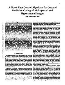
The Sequence Control System’s embedded system is described from three points of view. In order to highlight a system wide context, Figure 1 describes the component organization from an implementation point of view. The illustrations in Figure 2 outline how the principles of 3T’s high level control decomposition boil down to the actual application for ARTIS. Finally, Figure 3 shows the decision logic which is implemented as an UML State Chart model. IV.A.
Embedded Architecture Digital World Model
Mission Planning + Execution Monitoring
Mission Manager Supervisory Control System Module Manager Sensor Fusion
Sensor Status + Reactive Commands
Health Management
Task Planner Behavior Command Sequence
Route Planner
High Level Commands
• Resources • Cooperation • Communication
Operator
Behavior Command Sequence
Sequence Control System
User generated Behavior Sequ.
Event Handler Behavior Pool
UAV
Direct Commands
Low Level Commands
Flight Controller
Remote Control
Figure 1. The ARTIS Sequence Control System shown in the context of the high level system architecture. The gray areas relate to future components.
Two basic prerequisites of the proposed mission management architecture in Figure 2 are implemented in the Sequence Control System. The first prerequisite is a library of basic movement behaviors located at the reactive layer, followed by an executive component of the sequencing layer. Figure 1 shows that the Sequence Control System forms the interface to the flight control system. It is the unifying building block of the onboard Mission Manager and takes inputs from various sources like the ground control station, vision computer or supervision component. The higher level system components shown, relate to prospective components that demand a safe handling and robust coordination by the Sequence Control System. Furthermore, neither the deliberative layer nor the skills alone can handle all situations optimally. The Sequence Control System provides the necessary glue logic and is the place to store procedural knowledge that neither fits at the deliberative layer nor at the skill layer. For ARTIS, this procedural knowledge comprises some of the safety requirements for flight tests mentioned in chapter II. For example, when the safety pilot switches between manual or computer aided control, the system must stop producing actuator commands and reset its onboard components into a defined stand-by state. Figure 2 demonstrates which behaviors are located at the skill layer. Depending on which flight controller configuration is used, there are two basic behavior groups. The first group outputs direct position and velocity commands to the flight controller. The take-off and the landing behaviors use this controller configuration, where they command a fixed position for the horizontal layer (x and y axis) and a velocity command on the z axis. These behaviors contain only two state variables, namely the x and y position they have to maintain. As such, these behaviors are ”reflexive” behaviors in the original sense of the behavior-based paradigm.17 The second group is the largest set of behaviors. These produce trajectory-based control commands which comprise two tangential trajectory angles and the deviation from this tangent. At this time, the behavior library contains behaviors to wait at a position (”Wait For”), turn on the spot (”Hover Turn”), to
5 of 12 American Institute of Aeronautics and Astronautics
Deliberate Layer: High-level Behaviors using Task-specific Planners Fly Home
Explore
Search
Surveillance
… Mission Time
Sequencing Layer: Compile behaviors into plans Example: Mosaiking mission.
Photo Take Off
t0
Fly To
t1
Photo
Hover
t2a t2b
Hover To
t3
Hover
t4a t4b
Fly To
t5
Hover Land
t6
t7
Reactive Layer: Movement capabilities (skills) Take off
Land
Hover Turn
Hover To
Fly To
Path-based Flight Control
Velocity/Position-based Flight Control
Pirouette
…
…
Flight Controller Configuration (Task IDs) Figure 2. ARTIS’ Sequence Control System implements the executive component of the sequencing layer of this 3T architecture. The reactive layer contains basic movement behaviors that interface with the flight control system. The Sequencing Layer shows a mosaicking mission compiled from the behavior set.
fly along a linear trajectory toward a location (”Hover To”), to fly around a point along a horizontal circular trajectory (”Pirouette”), and to perform fast forward flights along an arbitrary trajectory (”Fly To”). The deliberate layer shows examples of prospective, complex behaviors. These will alter existing missions or even create new missions. In this context, mission planning will output the list of sequential behavior commands shown in Figure 2. However, the compilation does not necessarily take place onboard. In fact, at present, missions are compiled by the ground control station software and sent to the Sequence Control System. IV.B.
Event-based Model
As discussed in Chapter II, the Sequence Control System is exposed to a number of potentially concurrent events. Hence, the specification and implementation of the system is modeled as an event-based system.22 The majority of event-based systems are modeled using an industry-wide standard notation, UMLa . It supports the object oriented design pattern and provides dynamic modeling techniques such as state charts, sequence diagrams and activity diagram. State charts have been extensively studied such that abstract testing techniques allow to verify a model (semi-)automatically. Also, there exists good software tool support which eases the development process significantly. Moreover, there are tools that provide code generators such that the implemented code is directly derived from the state chart-based specification. Otherwise, it is likely that specification and implementation begin to diverge over time. Thus, the Sequence Control System is modeled as UML 1.2 State Charts. Basically, State Chart diagrams (also known as State Machines in UML 2) are finite automatons with a finite set of states where exactly one state is active at a time. They depict the dynamic behavior based on its response to events, showing how the model reacts to various events depending on its current state. Events can trigger a transition into another state, where so-called guards are the condition that must become true in order to traverse along the transition. The guards on similar transitions leaving a state must be consistent (deterministic) with one another. The UML model of the Sequence Control System is shown in Figure 3. It has two hierarchical levels where the top level models the procedural flow for a safe operation. The two composite states, ”Mission Mode” and ”Command Mode”, model mission plan processing and direct command execution respectively. Every state of the top level has a transition to the ”Mission Controller Off” to handle a manual control event, such that the Sequence Control System stands by in an idle state. If the system is in computer-based a Version
1.2, as defined by OMG (http://www.uml.org/)
6 of 12 American Institute of Aeronautics and Astronautics
StatechartOfCSequenceControl
DefaultTransition evManualPilot
MissionControllerO
ControllerOn evControllerOn
evManualPilot evManualPilot
evManualPilot evAutoPilot
evMissionModeStop
SlowDown
evDirectCommandValid evCommandStop
evMissionUpdate
evLanded
evStandStill
StandBy evDirectCommandValid evMissionModeOn
MissionMode
CommandMode
evDirectCommandValid evMissionModeOn evDirectBehaviorCommand (a) Main
StatechartOfMissionMode MissionMode DefaultTransition
evTimeOut
evTakeOffFinished
ParseCommand evCmdWaitingFor
evCmdTakeOff evLandingFinished
evHoverTurnFinished
evCmdLand
evCmdHoverTurn
evPirouetteFlightXYZFinished
evHoverToFinished evCmdHoverTo
evCmdPirouetteFlightXYZ
Page 1 of 1 evCmdPirouetteAroundXY
evCmdFlyToInit
evPirouetteAroundXYFinished evFlyToFinished WaitingFor
HoverTurn
HoverTo
FlyToInit
FlyTo
PirouetteAroundX
PirouetteFlightXY
Landing
TakeOff
evFlyToInitFinished
(b) Mission Mode Figure 3. The UML State Chart Model of the Sequence Control System comprises two composite states: State ”Mission Mode” for mission plan execution and ”Command Mode” for direct operator commands or commands from onboard components.
7 of 12 American Institute of Aeronautics and Astronautics
flight mode (auto mode), another idle state ”Stand By” lets the UAV hover at its current position when the state was entered; including a position on the ground. The state ”Slow Down” is necessary to assure a smooth changeover into ”Stand By” regardless of the flight maneuver currently being executed. In case the GCS operator commands the UAV to stop, a transition from every auto mode state assures that the command is executed. Among events certain priorities exist. For example, an event switching to manual mode is more important than a stop command and requires processing. The order in which the event check is performed accounts for this obligation. The state mission mode contains the actual library of behaviors. There are no transitions among behaviors which assures that not more than one behavior can be active at a time. This is a major requirement in order to overcome emergent behaviors caused by interactions. For each behavior there exists a termination condition which transits into the command parser ”Parse Command”. Basically this state grabs behavior commands from an existing mission plan (Figure 4). It issues an event for traversing into the appropriate state. If the mission plan is processed, ”Mission Mode” is finished. The ”Command Mode” can be entered from any auto mode state. It is relatively complex decision to determine whether a direct command is permitted or not. First, compared to behaviors in ”Mission Mode”, every direct command may not have a termination condition. For example, one instantaneous velocity command from the GCS cannot reach a target condition. For such cases, a quasi infinite behavior is bounded in execution time, such as the time passed since a GCS velocity command was received. Second, it depends on which data is coming on what input channels. This specific problem is addressed with the static truth table, shown in Table 1. This table defines the direct input data channels for the GCS, vision computer and FLARMb . The columns represent the data values, either boolean or numeric, for position, joystick, pattern position, stereo camera-based avoidance position, or a FLARM-based avoidance velocities. It names all valid, conflict free combinations explicitly. At runtime this table allows checks of every incoming command. input channel
Position
Joystick
Pattern Position
Stereo Obstacle Avoidance
allow external
-
-
true
true
true
false
false
false
false
false
on ground msgGCS ugcs b
FLARM Obstacle Avoidance
true
true
false
true
-
-
-
false
true
-
-
-
false
true
-
-
-
false
true
-
-
-
true
false
-
-
true
false
-
zgcs psigcs
true
false
-
-
-
true
false
-
-
-
msgvc xvc
-
-
true
true
-
-
true
true
-
yvc zvc
-
-
true
true
-
-
-
false
true
-
rvc
-
-
false
false
-
obststatvc
-
-
false
true
-
msgf larm sxf larm
-
-
-
-
true
-
-
-
-
true
syf larm szf larm
-
-
-
-
true
-
-
-
-
true
obststatf larm
-
-
-
-
true
vgcs
b wgcs b rgcs
b xgcs ygcs
-
Table 1. Truth table for direct command input. Commands coming from the ground control station (GCS) are either velocity (u,v,w,r) or positions (x,y,z,psi). A vision computer (VC) can output a pattern position (x,y) or a position command for obstacle avoidance (x,y,z). An integrated collision prevention system (FLARM) can output velocities (sx,sy,sz).
Likewise the command checks for these low-level direct commands, missions defined as sequence of behavior commands have to be understood as one single command. Although, for the system it is not possible to reason about the sense of a mission plan, it is possible to implement a plausibility check. These checks are implemented using the EBNF grammar23 shown in Figure 4, which ignores malformed behavior sequences that cannot be matched against it. EBNF grammars are formal grammars of logical production rules that comprise nonterminal symbols, similar to place holders or variables, and terminal symbols, which are generated by the grammar. Grammars are widely used to implement compilers for programming languages, and, as such, a behavior sequence is a sequential program. The grammar implemented in this context defines production rules for each behavior command or task flag, such as a ”hover to” or ”tracker off”. Its root is b An
integrated device for collision avoidance, http://www.flarm.ch/
8 of 12 American Institute of Aeronautics and Astronautics
defined by ”” which basically enforces every mission to start with a take-off behavior and end with a land. It implements some basic parameter checks, for instance for the ”hover and wait” command where the waiting time must not be a negative number. Furthermore, the grammar allows a check for any necessary preconditions for specific behaviors. For example, the trajectory planner for the forward flight needs at least three of its behavior commands. ID 20070510 TO -5 HV 0 0 -3 180 avoidance on WT 10 HV 33.3 3.51 -7 28.9 HV 37.1415 1.63484 -10 90 avoidance off WT 5 tracker on HV 37.1415 48.688 -10 90 HV 37.1415 48.688 -10 180 HV 31.81 48.688 -10 180 HV 26.4785 1.63484 -10 180 HV 26.4785 1.63484 -10 90 HV 26.4785 48.688 -10 90 HV 26.4785 48.688 -10 180 HV 21.147 48.688 -10 180 tracker off LD WO
::= ::= ::= ::= ::= ::= ::= ::= ::= ::= ::= ::= ::= ::= ::= ::= ::= ::= ::= ::= ::=
"ID" [] ; { | "0"}; "1"|"2"|"3"|"4"|"5"|"6"|"7"|"8"|"9"; [ [] "." ] ; { | "0"}; { | | }; { | | }; { | | | }; "TO" [ "-" ]; | | ; "HV" ["-"] ["-"] ["-"] ["-"]; "HT" ["-"] ["-"]; "WT" []; "WO"; { }; "FT" ["-"] ["-"] ["-"] ["-"]; "PI" ["-"] ["-"] ["-"] ["-"]; "PF" ["-"] ["-"] ["-"] ["-"]; "on" "off"; "tracker" | "avoidance"; "LD";
Figure 4. The mission (left) is an example for a behavior sequence that schedules a mission plan, including a pattern tracking section and a reactive obstacle avoidance section. The EBNF grammar (right) specifies the syntax for plausible behavior sequences.
IV.C.
System Testing
The overall complexity of the Sequence Control System’s software implementation imposes a thorough test strategy. The testing process has to account for user requirements (”scenarios”), as they were mentioned in Chapter II, and must address theoretical issues that can occur in finite state machine models and State Charts, respectively. Basically, there are four testing stages during the development of the onboard mission management system: 1. Abstract tests assure that the model is free of principle errors. 2. Unit Tests assess the functionality of individual software component or a composite component. 3. Simulation provides the infrastructure for operational tests that assess the overall system integration. 4. Flight Tests provide a practical proof of concept for the real world application. In the modeling stage a set of errors can occur. Some relate to potentially isolated or unreachable states, as well as, missing or erroneous triggers and guards. An even more fundamental problem is the theoretically infinite set of sequences that have to be tested in an abstract manner. That is, regardless of the meaning and function behind events, states and transitions, the tests must traverse through the model even if a certain test would make no sense from a practical point of view. Abstract tests relate to Model-based testing.24 In the case of the Sequence Control System, the test model can be derived from the State Chart model. UML state charts represent a constructive model,25 such that tests can make use of its internal structure (known as white-box testing). These abstract tests can be divided into three groups, namely the path coverage, transition coverage and state coverage tests as highlighted in Figure 5. For each of these groups, a set of event chains is generated and executed. Once a full coverage of all possible combinations is reached, the tests are completed. However, there is no defined final state and states can have loops, as such infinitely long test chains for path coverage tests result. Therefore, a relaxation for the path coverage criteria is implemented such that loops must be passed only once. This is a strong and feasible criteria.24 Inspired by some of the best practices in XP,26 the user requirements are translated into scenarios that are implemented as Unit Tests. The tests focus solely on the observed behavior (known as black-box testing). 9 of 12 American Institute of Aeronautics and Astronautics
Sequence 1
Sequence 2
Sequences 3
Sequence 4
Sequence 1
(a) transition coverage
Sequence 1
Sequence 2
Sequence 3
(b) state coverage
Sequence 2
Sequences 3,4
Sequences 5,6
Sequences 7,8
(c) path coverage Figure 5. Abstract testing strategies for State Charts based on coverage of a) transitions, b) states and c) paths.
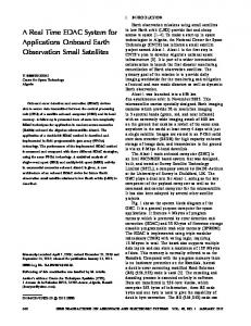
XP’s test-first practice allows an ”inside-out” strategy where each component, for example a trajectory interface, is tested before a higher component is tested that makes use of this interface. Technically, the tests implement certain heuristics. For example, if the GCS does not send new velocity commands, a time out must trigger an appropriate event. Besides these procedural checks, some behaviors can be tested using Unit Tests, such as the landing behavior, which must stop descending when a certain level of lateral or longitudinal velocity is exceeded. Other scenarios intentionally produce illegal commands which the system must ignore. For instance, when the UAV stands on the ground any direct command must be ignored, except the take-off command. Furthermore, the system always has to check against a shortfall of minimum ground distance, which can be tested easily using simulated data. Essentially, these unit tests also serve as so-called regression tests.27 It is possible to find ”local” bugs, that is, test whether changes introduced new bugs. Then they can ”unmask” previously existing bugs that were not detected before. Finally, they potentially uncover unintended side effects with ”remote” tests, where the change of one part breaks another part of the software. Before every flight test, the fully integrated Sequence Control System software is tested in simulation. For ARTIS, SITL and HITL simulations are available as shown in Figure 6. The SITL simulation implements a number of simplifications for the sake of reducing the computational load on desktop PCs. Whereas the HITL simulation uses the original onboard computer hardware and realistic sensor models. Moreover, the SITL simulation runs in a Simulink model which does not enforce real-time code execution. Further, most state chart events are based on thresholds, time outs and distinct sensor values. With respect to the Sequence Control System, the major difference between SITL and HITL simulations is, that sensor values, timing conditions and event sequences differ. Logic tests in abstract and unit testing cannot check the correctness of the effective interface to real valued state estimates and sensor data. These issues are addressed during the operational tests in these simulations. Predefined functional tests are executed manually, then missions that provide a full state coverage are executed.
V.
Future work
In theory many high level control problems of the UAV domain, like path planning or performing a single maneuver, are considered to be solved. However, integrated architectural concepts can rarely be observed in flight tests. That is why the focus is on the difficulty of bridging theory and practice, which was the goal in this paper and will be an important future research aspect within the ARTIS program. In order to achieve this goal, a number of research directions have been identified. In the short term, the onboard mission management concept will be extended by a decision making component that reacts on potential error situations, such as a data link loss to the ground station. Moreover, work is underway to explore alternative modeling techniques, such as Petri Nets. Additionally, behaviors for the deliberate layer are developed that allow an operator to perform tasks like object search and tracking, exploration or flying back to a base.
10 of 12 American Institute of Aeronautics and Astronautics
Real-time Simulation Control
Actuator Model
Flight Mechanical Model
Actuator Raw Data
Actuator Driver
States
Sensor Models
Raw Sensor Data
Actuator Commands
Flight Controller
State Estimates
Navigation Filter
Sensor Data
Control
Actuator Model
Flight Mechanical Model
Actuator Commands
Actuator Driver
Sensor Drivers
Sensor Models
Raw Sensor Data
Actuator Raw Data
Flight Controller
State Estimates
Sensor Data
Navigation Filter
Sensor Drivers
Control Commands
Control Commands
Missionmanager
Missionmanager
(Sequence Controller)
(Sequence Controller)
High Level Commands
States
High Level Commands
Telemetry
Simulation Computer
Ground Control Station
Flight Control Computer Telemetry
Ground Control Station
(a) Software-In-The-Loop
Ground Control Station
(b) Hardware-In-The-Loop
Figure 6. Functional tests of the Sequence Controller are performed a) in full software simulation and b) on the real flight control system with simulated sensor inputs.
VI.
Conclusion
This paper presents a solution to the onboard mission management problem of UAVs. It is implemented in the unmanned helicopters used by the ARTIS program and successfully validated, verified and flight tested. This behavior-based Sequence Controller System, embedded into a 3T architecture is a feasible approach and has advantages over the discussed approaches. The UAV is controlled by a robust, deterministic system that can handle various events and commands coming from multiple sources. These sources can either be system components or a remote operator. The presented (semi-)automatic test process makes testing manageable and allows test execution in a repeatable way. The Sequence Control System is the executive part of a 3T architecture which allows different levels of UAV autonomy. The behavior-based aspects of the proposed architecture enable real-time properties through a direct linkage between sensors and actuators, even for complex maneuvers. New behaviors can be added to the behavior library such that functional extensibility is facilitated (”plug-and-fly”). Since some concepts of solely behavior-based approaches, like arbitration or robot learning, are not eligible for UAV control, they have not been implemented in the architecture. The State Chart model assures an event-based behavior with deterministic, predictable actions. The decision logic can be verified using abstract tests like state coverage, path coverage and transition coverage tests. The level of abstraction in the State Chart model allows a convenient way of mission execution and execution monitoring. The Sequence Control System implements several operational safety features. First, an operator can overrule autonomous actions anytime. Second, the system provides a stand by state which also serves as a fall-back state in case of errors. Third, the user input is checked against plausibility rules using a truth table and an EBNF grammar. Regardless of which behavior is executed or what operator command the system is executing, the system allows no shortfall of a minimum ground distance, thus avoiding accidental ground strikes. Furthermore, it rejects a malformed mission plan, that is a plan which could harm the helicopter during mission execution. By design the Sequence Control System keeps the operator in the loop. He has the possibility to intercept any running behavior by different kinds of commands, ranging from direct velocity commands (e.g. for remote joystick control), direct position commands, a single behavior (e.g. land) or a complex behavior command sequence. Furthermore, at this time, high-level tasks like mission planning remain operator tasks. It is possible to implement an ”onboard operator” in case an operator on ground is not available. However, the control architecture may reach its limits when the centralized sequencer needs to implement concurrency (e.g. multiple deliberate behaviors need to be active). It does not allow concurrency between all behaviors and modules in the system. Moreover, known shortcomings of State Chart models are inherent to the current system. First, State Charts need constraints to restrict semantics on the input data since these cannot be modeled. Second, UML use cases are user examples and as such inherently incomplete. A formal specification of the functional requirements is be desirable. State Chart models provide only a limited support for temporal design aspects.
11 of 12 American Institute of Aeronautics and Astronautics
References 1 Dittrich, J. S., Bernatz, A., and Thielecke, F., “Intelligent Systems Research Using a Small Autonomous Rotorcraft Testbed,” 2nd AIAA ”Unmanned Unlimited”, No. AIAA-2003-6561, San Diego, CA, September 2003. 2 Bonasso, R. P., Firby, J., Gat, E., Kortenkamp, D., Miller, D. P., and Slack, M. G., “Experiences with an Architecture for Intelligent, Reactive Agents,” Journal of Experimental & Theoretical Artificial Intelligence, Vol. 9, No. 2/3, April 1997, pp. 237–256. 3 Heitzmann-Gabrielli, L., “Mission Planning and Dynamic Avoidance for Groups of Autonomous Agents,” Trabalho de Graduacao, Instituto Tecnologico de Aeronautica, Sao Jose dos Campos, Brasil, Nov 2005. 4 Dittrich, J. S., Adolf, F., Langer, A., and Thielecke, F., “Mission Planning For Small Uav Systems In Uncertain Environments,” 2nd European Micro Aerial Vehicle Conference, Braunschweig, Germany, July 2006. 5 Shim, D. H., Hierarchical Control System Synthesis for Rotorcraft-based Unmanned Aerial Vehicles’ , Ph.D. thesis, University of California, Berkeley, 2000. 6 Fabiani, P., “The RESSAC Autonomous Air Vehicle Project: Challenges and Demonstration Platforms,” 5th ONERADLR Aerospace Symposium, June 2003. 7 Piquereau, A., Fuertes, V., and Fabiani, P., “Autonomous Flight and Navigation of VTOL UAVs,” 5th ONERA-DLR Aerospace Symposium, June 2003. 8 Schrage, D. P. and Johnson, E. N., “The Georgia Tech VTOL UAV Testbed - The GTMax, As an Open System for UAV Research and Development,” 59th Annual Forum of the American Helicopter Society, Phoenix, AZ, May 2003. 9 Hill, R., Chen, J., Gratch, J., Rosenbloom, P., and Tambe, M., “Intelligent agents for the synthetic battlefield: A company of rotary wing aircraft,” Innovative Applications of Artificial Intelligence (IAAI-97), 1997. 10 Putzer, H. and Onken, R., “COSA A generic cognitive system architecture based on a cognitive model of human behavior,” Cognition, Technology and Work , Vol. 5, 2003. 11 Weiss, L. G., “Intelligent Collaborative Control For UAVs,” Infotech@Aerospace, Arlington, Virginia, 26-29 September 2005. 12 Freed, M., Bonasso, P., Dalal, K. M., Fitzgerald, W., Frost, C., and Harris, R., “An Architecture for Intelligent Management of Aerial Observation Missions,” Infotech@Aerospace, Arlington, Virginia, 26-29 September 2005. 13 Egerstedt, M., Hu, X., and Stotsky, A., “A Hybrid Control Approach to Action Coordination for Mobile Robots,” Proceedings of IFAC 99 14th World Congress, Beijing, China, Jul 1999. 14 Laird, J. E., Newell, A., and Rosenbloom, P. S., “SOAR: An Architecture for General Intelligence.” Artif. Intell., Vol. 33, No. 1, 1987, pp. 1–64. 15 Musliner, D. J., Hendler, J., Agrawala, A. K., Durfee, E. H., Strosnider, J. K., and Paul, C. J., “The Challenges of Real-Time AI,” Tech. Rep. CS-TR-3290, 1994. 16 Agre, P. E. and Chapman, D., “Pengi: an implementation of a theory of activity,” Computation & intelligence: collected readings, American Association for Artificial Intelligence, Menlo Park, CA, USA, 1995, pp. 635–644. 17 Toal, D., Flanagan, C., Jones, C., and Strunz, B., “Subsumption Architecture for the Control of Robots,” IMC-13, Limerick , 1996. 18 Brooks, R. S., “A robust layered control system for a mobile robot,” Morgan Kaufmann Publishers Inc., San Francisco, CA, USA, 1990, pp. 204–213. 19 Pirjanian, P., “The Notion of Optimality in Behavior-Based Robotics,” Journal of Robotics and Autonomous Systems, 1999. 20 Makowski, P., “Survey on Architecures and Frameworks for Autonomous Robots,” November 2004. 21 Simmons, R., “Structured Control for Autonomous Robots,” IEEE Transactions on Robotics and Automation, Vol. 10, No. 1, February 1994. 22 Muehl, G., Fiege, L., and Pietzuch, P., Distributed Event-Based Systems, Springer-Verlag New York, Inc., Secaucus, NJ, USA, 2006. 23 ISO-14977, “Information Technology Syntactic Metalanguage Extended BNF,” 2001, International Organization for Standardization, ISO/IEC 14977. 24 Utting, M. and Legeard, B., Practical Model-Based Testing: A Tools Approach, Morgan Kaufmann Publishers Inc., San Francisco, CA, USA, 2006. 25 Rumpe, B., Agile Modellierung mit UML : Codegenerierung, Testfaelle, Refactoring (Xpert.press), Springer, November 2004. 26 Wright, G., “Achieving ISO 9001 Certification for an XP Company.” XP/Agile Universe, 2003, pp. 43–50. 27 Agrawal, H., Horgan, J. R., Krauser, E. W., and London, S., “Incremental Regression Testing.” ICSM , 1993, pp. 348–357.
12 of 12 American Institute of Aeronautics and Astronautics