miniature, Teflon solenoid valvewhich has a dead volume smaller than 50 tl and an activation time about 8 ms [3]. The valve driver is an electronic device which.
Journal of Automatic Chemistry Vol.
11, No.
(January-February 1989), p. 1-14
A simple, automated device for the precise addition of liquids Gary W. Kramer?,
Jose
M. Hanquier, A. Roger
MINIATURE SOLENOID VALVE
Frisbee and Philip L. Fuchs
LIQUID
PRESENCE DETECTOR
Department of Chemistry, Purdue University, West Lafayette, Indiana 47907, USA
N2 IN
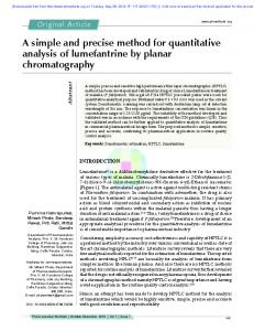
Metering liquid reagents into reaction mixtures in a controlled and reproducible manner has often been a problem in synthetic chemistry. Carrying out the real simultaneous addition of two or more liquid reagents (concurrent additions) is even more inconvenient. Difjculties increase when addition volumes become small, when addition times become long, or when the reagents are corrosive or air-sensitive. We have constructed and tested an inexpensive, automated device for the slow, precise delivery of liquid reagents into laboratory-scale reaction mixtures. Controlled by a standard personal computer, this slow adder can accommodate liquid
ADJUSTABLE BUBBLER REAGENT RESERVOIR
REACTOR
OUTPUT
EXIT BUBBLER
INPUT
CONPUTER
volumes from hundreds of microlitres to litres and addition times from minutes to days. Its glass and TeJlon construction makes it useful for nearly all reagents. By using multiple slow adders, true concurrent addition of several liquids can be easily achieved.
Figure 1. The slow adder apparatus for liquid additions. is opened, and the pressure drop across the system, a precise delivery of reagent can be achieved.
The slow, constant introduction of liquids into reaction mixtures has long been a problem in laboratory-scale organic syntheses. The rate of reagent addition is often a critical variable in determining the outcome of a reaction. However, addition rates are usually specified in nebulous terms such as ’the solution is added dropwise over an hour’ or ’the material was added slowly over a period of 5 min’. These statements seem to imply that material was added at a linear rate during the prescribed interval. In actual practice this is rarely the case since precise additions are difficult with the apparatus commonly employed. Failure to account for rates of reagent addition can lead to irreproducibility in experimental results. Traditional devices such as ’constant addition’ funnels, even when fitted with stopcocks containing needle valves, are difficult to adjust to provide constant addition rates. Syringe pumps and dispensers permit easy flow rate control, but suffer from ’freeze up’ problems when used with air-sensitive reagents or solutions of solids dissolved in volatile liquids. The volume deliverable from syringe pumps without resetting is limited to 100 ml. Metering pumps, while usable with large volumes, are not suitable for delivery of small amounts of expensive reagents.
The heart of the slow addition device (slow adder) is a miniature, Teflon solenoid valve which has a dead volume smaller than 50 tl and an activation time about 8 ms [3]. The valve driver is an electronic device which converts the computer output signal into a precisely controlled, high current drive for the valve. A potentiometer adjustment on the valve driver is used to set the open-time of the valve [4]. The adjustable bubbler [5], used to set the pressure drop across the system, must provide a pressure slightly higher than that of the exit bubbler so that liquid will flow from the reservoir to the reactor when the valve is open. The liquid presence detector [6], used to determine the beginning and end of addition, as well as certain error conditions, should be placed as close as possible to the reactor. The system plumbing is 0"063 in or 0" 125 in OD Teflon or Teflon-FEP tubing with ChemInert flare fittings. In the standard system, a reagent comes in contact only with glass and Teflon. The valve driver and liquid presence detector are designed to work with TTL level signals such as those normally found on a computer’s parallel I/O ports. An additional interface must be employed to allow the slow adder to use the RS-232 levels typically found on a computer’s serial I/O port [7].
Continuing development of an automated synthesis system [1] rekindled the authors’ interest in a device for the slow addition of reagents which could be controllable by a general-purpose computer. The current apparatus (figure 1) is an adaptation of a logic-controlled device developed several years ago for bench-scale reagent additions [2]. The equipment consists of a pressurized reagent reservoir, a computer-controlled solenoid valve, and a liquid presence detector. By accurately controlling the time that the valve is open, the rate at which the valve
The rate of reagent addition is determined by several variables:
(1) The pressure drop from the reservoir to the reactor. (2) The length of time that the valve is open. (3) The rate at which the valve is opened.
Author to whom correspondence should be addressed.
0142-0453/89 $3.00
TO VENT
TO VENT
(C)
1989 Taylor & Francis Ltd.
G. W. Kramer et al. A simple device for the precise addition of liquids
(4) The length and inside diameter of the delivery tubing. (5) The viscosity of the liquid being transferred. The apparatus is assembled as shown in figure 1. The pressure differential between the reservoir and the reactor is adjusted along with the valve open-time to produce the required ’drop size’ [8]. A simple computer program pulses the valve open and closed while these manual adjustments are made. For accurate work, the system must be calibrated under conditions as close as possible to those of the actual delivery. A known volume of the reagent is placed into the reservoir, and the valve is pulsed until the liquid presence detector senses the liquid [9]. The computer then counts the number of pulses issued until the detector signals no more liquid. A calibration factor is calculated from the known volume of reagent and the number of pulses required. The computer program [10] for a controlled addition required the calibration factor, the desired addition time, and the volume of reagent to be added. When these constants are provided, the valve is pulsed rapidly until the detector senses liquid, then the pulse rate is adjusted to that required to give the desired addition time. The program monitors the total addition time and returns an error message if the addition is not complete in 120% of the allocated time. When the reagent is completely added, the true addition time is reported. The utility of the slow adder can be extended by driving two or more valve drivers from the same computer signal. If each valve subsystem is properly calibrated, a true simultaneous addition of several reagents can be achieved. For best results the reservoirs of each valve system should be pressurized from the same adjustable bubbler. The delivery tubing of each system should be as identical as possible. The reagent concentrations and solution viscosities should be equal. By listening carefully to the clicking of the valves and adjusting the potentiometers until only a single click is heard, the open-time of each valve can be made coincident. The precision of this aural method appears to be equal to that achieved by using an oscilloscope to view the drive signals.
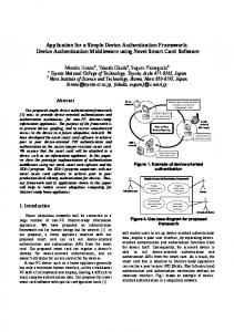
To more tblly understand the operation of our slow adder, we carried out detailed studies on addition of six liquids (Et20, hexane, THF, water, EtOH, and a 50:50 by weight mixture of ethylene glycol:water). In each study, the volume delivered was 4"0 ml, the requested delivery time was 30 min, the delivery pressure was 20 mm Hg, and the valve open-time was 100 ms. The calibration factor was obtained from a previous run using a 3 ml volume of the liquid. The apparatus was assembled much as shown in figure 1, except that the reactor and exit
bubbler were replaced by a receiving flask placed on a computer-readable balance. The receiving flask was constructed from a 50 ml volumetric flask with its neck replaced by a 4 mm ID tube, 65 mm long, through which a 100 mm 19-gauge syringe needle delivered the liquid without touching the sides. This design was chosen to minimize solvent evaporation in the open flask during the tests. The solvent reservoir was a 5 ml Wheaton vial fitted with a 66 mm 19-gauge syringe needle with a flat-cut tip leading directly to the bottom. The delivery tubing was 1"0 mm ID and was connected to the valve with ChemInert flare fittings and to the syringe needles with Kel-F Luer to Chem-Inert adapters. Two configurations of the slow adder, which differed only in the length of the interconnecting tubing, were examined. The short system incorporated 380 mm of tubing while the long system had 775 mm of tubing. The results of these studies are shown in table 1. Figure 2 shows the delivery of water in both the long and short system. Delivery of the other liquids produced similar graphs. In each of the curves, certain regions can be identified. Points in the base region labelled ’A’ occur while the liquid is filling the delivery tube and has not yet reached the balance. The linear region, ’B’, represents the time when both the delivery tube and the reservoir contain liquid. The curved section, ’C’, is produced when the reservoir is empty, and the delivery tube is being drained. Finally, the flat region, ’D’, shows that the delivery is complete. Weight (g)
Long Stjstem Short Sgstem
D
The applicability of the slow adder system is not limited to simple timed reagent additions. By incorporating other computer-readable sensors, such as reaction temperature or pH probes, the computer can be programmed to deliver reagents at rates dependent on other factors. A more sophisticated computer program than the timed addition routine would be required to control such closed
loop processes. Our initial slow adder qualification tests consisted of metering in ml aliquots of liquids (THF, Et20, CH2C12, hexane, toluene, and water) over intervals ranging from 5 min to 10 h. In addition, we transferred several 100 ml portions of THF over to 3 h. In all cases, the true addition time was within 8% of the requested time. We were able to demonstrate the suitability of the slow adder for use with air-sensitive materials by delivering ml aliquots of a solution of 0"10 M MeLi in Et20 with no change in titre.
Yaive Pulses
O. 0000
150. O0
Figure 2. The addition
300. O0
450. O0
600 O0
750
of water using the slow adder.
A simple model of the laminar flow of liquid in
a
horizontal tube shows that the volume flow rate should be directly proportional to the pressure differential across the tube and proportional to the fourth power of the tube’s inside diameter, but inversely proportional to the viscosity of the fluid and to the length of the tube (see Appendix 1.D) [11]. The slow adder is a more complicated system than a simple tube, and violates several of the assumptions used to derive the simple flow model.
G. W. Kramer et al. A simple device for the precise addition of liquids
Table 1. Slow adder performance. Cal. Factor
pulses/ml
Liquid
Slope mg/pulse
% RSD Slope*
% Total delivery
12’4
-4"7
6"4 4"3
0"14 0"26 0’19 0’30 0"21 0"50
8"8 7"8 7"3 6"2 4"8 3"1
0"21 0"22 0"19 0"72 0’19 0"23
-3"8 -0"2 -6"7 +5"1 +2"3 +5"8
Short system (tubing volume 300 tl, total dead volume 665’ 1) 47 Et20 55 n-C6 70 THF 112 H20 EtOH 118 274 Glycol** Long system (tubing volume 610 tl, total dead volume 975 tl) 73 EtO 73 n-C6 THF 125 148 HO 153 EtOH 321 Glycol**
10"9
12"2 9"2
Time deviation
-2"7 -4"7 -3"3 -0"9 -8"0
Conditions: 3 ml calibration volume, 4 ml delivery volume, 30 min requested delivery time, 20 mm Hg delivery pressure, 100 ms valve
open-time. * Linear portion of delivery curve ** Ethylene glycol:water 50*50 by weight.
I
COOH
(I-IzC)ll OH
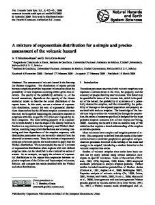
1) 2,2,_DIPYRIDYL DISULFIDE in XYLENE, 25Oc, 5h 2) ADD DROPWlSE TO BOILING XYLENE OVER 15h
1 Scheme 1. Cyclic lactonization
-
CO
I[
(HzC)ll
"O 2
-[- (H2
CO- 0 /
Ck)
\
(C 2)11
/H
11
O--- CO 3
of w-hydroxyalkylcarboxy’lic acids using the slow adder.
However,
it is reassuring that the slopes of the linear region of the addition curves (which represent flow rates) show inverse, though not completely linear, dependencies on both liquid viscosity and tube length. Also the shape of the flow curves in region C can be derived from the flow model (see Appendix 1.D).
The shape of the delivery curves affect the delivery time accuracy of the slow adder. Calibration is usually done by placing a known volume of the liquid in the reservoir and then counting the number of pulses required to totally dispense it. Starting and stopping the pulse counting is done on signals from the liquid presence detector mounted as close as possible to the reactor. The calibration factor is calculated by dividing the number of pulses required by the volume delivered. The increase in rate that occurs while the delivery tube is drained causes an error in the calibration. This error is exacerbated by longer tube lengths which cause the C region of figure 2 to become larger. Minimizing the lengths of the tubing between the reservoir and the reactor will reduce the error, but since the slow adder is a ’to contain’ device, it will always be present. The use of small calibration volumes can also lead to larger errors- the number of pulses in the B region decreases in relation to the number of pulses in the C region.
A better calibration factor can be obtained by either counting the number of pulses required to deliver a
certain weight of liquid onto a balance or to deliver a certain volume to a volumetric measure when the slow adder is in the linear region of its delivery curve. However, these methods require either additional automated equipment or human intervention.
To provide a complete application of the slow adder, a reported lactonization procedure [12] was ’carried out (Scheme 1) reagent addition had been done in this over 15 h using a mechanical syringe drive. A mixture of 12-hydroxydodecanoic acid (0"108 g, 0"5 mmol), 2,2’ dipyridyl disulfide (0"165 g, 0"75 mmol) and triphenylphosphine (0.197 g, 0"75 mmol) was dissolved in dry, oxygen-free xylene and stirred at 25 C for 5 h. The slow adder was calibrated by adding 10 ml of xylene from the reservoir to the reactor containing 90 ml of xylene at reflux under nitrogen (calibration factor: 0"008 ml/valve pulse). The solution of hydroxyacid was transferred to the addition reservoir and added under computer control 15"0 h, to the boiling xylene (specified addition time 16.1 h). The addition reservoir actual addition time was rinsed with ml xylene, which was flushed into the reactor. After heating at reflux for an additional 10 h, the solvent was removed under reduced pressure and the ether-soluble portion was purified by silica gel chromatography using 2% THF-hexanes to yield 0"075 g (0"379 mmol, 76%) of the desired lactone 2 (reference yield 66% after recrystallization). The product identity was confirmed by spectral comparison to an authentic sample 13].
G. W. Kramer et al. A simple device for the precise addition of liquids
To demonstrate the utility of the device for
true concur-
additions, two valves were driven from one input signal. Two 100 ml reservoirs were pressurized from the same adjustable bubbler (about 15 mm Hg). The valve open-times were set aurally and verified by oscilloscope measurement of the drive signals (time open about 50 ms). The repetition rate was set at one drop every 5 s. Delivery tubes consisted of identical 18-gauge syringe needles with 18 in cannulae leading from the reservoirs to the valves and from the valves to an open 150-ml beaker (reactor). One reservoir was charged with 0"102 M HCI solution and the other was filled with 0"102 I NaOH solution. The concentrations of the acid and base were painstakingly adjusted to be equal. The beaker was fitted with a magnetic stirring bar, about 10 ml of water, and a few drops of methyl purple indicator [14]. Stirring was begun, and the colour of the liquid in the beaker was adjusted by dropwise addition of acid and base to give the neutral grey colour. The simultaneous addition of the acid and base was begun. Green and purple flashes of colour could be seen in the beaker as addition proceeded, but the overall grey liquid colour was sustained until over 25 ml of acid and base had been added. A purple tinge then began to develop, and the addition was terminated. Less than one drop of the acid or base was required to completely change the colour of the liquid in the beaker from grey to violet or green. rent
Electrical schematics for the valve driver, liquid detector, optional RS-232 interface, mechanical specification for the liquid detector, a derivation of a simple liquid flow model, and a source listing of a sample timed addition program are found in Appendix 1.
7. The RS-232 control signals DTR and DCD are used to send the valve output pulse and to receive the detector input. If the control signal to the valve driver is derived from a switch or relay contact closure, it must be thoroughly debounced to avoid multiple triggering of the valve driver. 8. When the delivery line between the valve and the reactor is short, the valve closing action ejects the ’drop’ into the reactor. Under these conditions it is possible to add reagents in smaller increments than is possible with gravity fed devices. 9. A liquid/no-liquid decision by the computer requires five consecutive valve-pulse/detector-read sequences to be valid. This avoids problems with small bubbles which may form in the delivery line during prolonged additions with volatile solvents. It is essential that the tapered-bottom reservoir have its flat-cut-tipped eductor tube extending completely to the bottom. In this way all the liquid can be drawn through the tube before air bubbles become entrained in the flow. 10. The control programs are written in the C programming language and have been ported to IBM-PC (MSDOS) and CompuPro 8/16 (MSDOS and CP/M 80) computers. It is possible to write such programs so that they operate in a background mode, leaving the computer ostensibly free for other tasks. 11. Fox, R. W. and McDoNAII), A. T. (John Wiley and Sons, New York, 1985), p. 347. 12. CoREY, E.J. and NICOLAOU, K. C., Journal of the American Chemical Society, 96 (1974), 5614. 13 The reference lactone was prepared by meta-chloro perbenzoic acid oxidation ofcyclododecanone (CH2C12, 25 72 h), standard work-up, and silica gel chromatography with 2% THF-hexanes. 14. Methyl purple is an acid-base indicator mixture containing an inert blue dye. The concentration of dye is adjusted so that the acid colour (pH +sv lOM I=" TA
IO/4F T’A
CL 7660
15
IO F
3 C O 1"4
>-sv E> COM
[E +5
co IE>’
,
ll ICOM 20pF
C2 c5
CI
o00o
0o0o
IS -I,59
G. W. Kramer et al. A simple device for the precise addition of liquids
Appendix I.D Mechanical specification of liquid presence detector
’----_-21
___./--)--
I---
),
Appendix I.E Derivation of a simple liquid flow
but
Vp
(1/2 D)2 L
model Simple liquid flow model derivation Basic assumptions
(1) (2) (3) (4)
Laminar flow in horizontal tube
Substituting (3)in (1)gives"
Steady flow Incompressible fluid Fully developed flow Symbols and units
ut
Let K be
Q: Flow in m3/s D Internal diameter of tube in m L: Length of tubing in m AP. Pressure in Pa :Viscosity in poise (1 poise 0.1 kg/ms) Vp Volume of liquid in tubing in Vd: Volume of liquid delivered in gAP D 4 Q= 128 (0.1 ) L and
2 AP D 6
dV
Q
dt
g2
AP 0 6
(4) (5)
Substituting (5)in (4) and integrating gives" vl(O
y VdV=KIt o
(6)
(K/2)
(7)
V(o)
(1) (2)
which gives:
V(o> with
Vl(t Vp(0)
V2(0
volume in tubing at time volume in tubing at time 0.
G. W. Kramer et al. A simple device for the precise addition of liquids
But V(o)with
Vd(t)
requested volume and checks if the computed pulsing actually smaller than pulse/sec.
rate is
volume delivered at time
v c0 Substituting (8)in (7) and developing gives: (K/2) V2d(t) 2 Vp(O) Vd(t)
(8) include "pcadder.h"
(9)
Application For the long system with water, we get: K 1"756 10 -13 m 6 s -1 10 .6 m 3 ml Vp(0) the tube: 5"67 s. drain to time Computed required Measured time required to drain the tube: (6 + 0"1) s.
main
{ sladder(); long ftol(), mintime; float calfact, vol, rate, slcalib(); int time, truetime,
/* Calibrate the slow-adder */
printf("\nEnter the calibration volume:"); scanf("%f", &vol);
Reference 1. Fox, R. W. and McDONALD, A. T., Introduction to Fluid Mechanics (John Wiley and Sons New York, 1985), 347.
Appendix I.F MS.DOS slow-adder control software listings
calfact
slcalib(vol);
printf ("\nCalibration factor if (calfact
%f’, calfact);
< O)
{ printf("’Nnlncorrect calibration, job aborted"); exit();
Program pcrunadd.c
}
/* FILE: PCRUNADD.C */
/* Getting run parameters */
Desc: Main program to run the slow-adder from a PC Date: 02/11/88 Vers: 1.00
vol=time=0; while
(vol
MAXPULSE)
{ printf("\nPulsing
rate exceeds slow-adder limits
exit(); The volume to be delivered is a decimal number of ml, and the requested delivery time is given in minutes. (The smallest value advised is 10 min.) The program computes the minimum time allowed to deliver the
} printf("START TIME");/* Getting start time */ ptime();
G. W. Kramer et al. A simple device for the precise addition of liquids
60 * (long) time * TIMEMULT :/* max maxtime addtime 125% of calculated*/ printf("\nMaximum time allowed %ld s", maxtime);
if( (truetime stadder( vol, time, calfact )) lml for best results)
*/ #include "pcadder.h"
sladder( vol, time, calfact) int time; float vol, calfact;
{ int err;
unsigned int delay; long addtime, maxtime, sladd(); /* Computation of delay between 2 pulses expressed in milliseconds */
delay ftoi( 60 * (long) time / vol/calfact * 1000 ); printf ("\nDelay between 2 pulses %ud ms", delay);
After priming, pulses the slow-adder every second until no liquid is detected by the liquid detector. Computes the calibration factor as ml delivered / no of pulses. Requires 5 negative readings in a row to declare
delivery complete.
Returns -1 if priming error (no liquid to sensor in 40 pulses) or too many pulses required (maximum number of pulses volume / fastest pulsing rate, i.e. pulse / sec), otherwise returns calibration factor in ml/pulse (drop size).
#include "pcadder.h"
G. W. Kramer et al. A simlSle device for the precise addition of liquids
* Function slflush() flushes the slow-adder by pulsing 40 times with a pulsing rate of pulse/sec.
float slcalib(calvol) float calvol;
{ int pulses, maxpulse, i, err; float cal,rate;
slprime()
printf("\nBeginning calibration");
prime slow-adder for addition _*/
maxpulse
calvol / MINCALIB;
/* max pulses permitted */
slprime()
( if(
/* PRIME TO SENSOR */
slprime()
err
int i, j;
return( (float)err); /* Add until no liquid to sensor, pulsing rate
pulse/sec pulses number of pulses pulseadder() function to pulse the slow-adder once sleep(1000) waits 1000 ms between 2 pulses */ for( i=0, pulses=0 < ADDOK pulseadder(), pulses++ sleep(1000) if( pulses >= maxpulse return( ADDERR); else if( readsensor()
for( i=0,j=0 j < PRIMOK sleep( PRIMD ), pulseadder(), + +) if(i > PRIMMAX-1) return( PRIMERR ); /* error ifno liquid found */ else if(readsensor() j + +; /* PRIMOK pos. reads before start ofaddn else
j=0
/*if no liquid, reset index */
return( 0 );
i++; else
sladd()
i=0;
perform addition and return elapse time ,/
/* FLUSH OUT TUBING */
slflush();
}
long sladd( delay, maxtime unsigned int delay; long maxtime;
C routines pcctrl.c
int i;
return((float) (calvol/(pulses + PRIMOK-ADDOK)));
{ long starttime, gettime(), checktime();
/* FILE SLCTRL.C
starttime
Desc: Functions
to
gettime();
/* records starting time *
prime, add a volume and flush the
for( i=0;i