we presented a simple compression method and we proposed the improved method by ..... types of movies were encoded by using the simple com- pression.
A Simple Compression Method Using Movion Vector of Video Encoder in the Destributed System Yasuyuki Miura½ , Sho Nakane½ and Shigeyoshi Watanabe ½ ½ Shonan Institute of Technology,1–1–25, Tsujido-nishi-kaigan, Fujisawa, Kanagawa 251–8511, Japan
Abstract— With the technological advancements of PCs, it has been possible to edit and encode video using software. Parallel processing has been possible with low-price PCs. We have developed a parallel encoding system for a cluster or Grid with multi-core PCs. Because the transmission between PCs may become bottlenecked if an uncompressed video image is the first sent, we have proposed a simple compression that can be transmitted via a LAN. In this paper, we presented a simple compression method and we proposed the improved method by using motion vector from video encoder. Also, the results of our performance evaluation were presented. As a result from some experimentation, � �� maximum and � �� average of the data amount were reduced by using motion vector.
Keywords: MPEG, Destributed Processing, Video Encoding
1. Introduction With the technological advancements of PCs, it has been possible to edit and encode video using software. Parallel processing has been possible with low-price PCs. However, the software[1][2] encoding of video images still places a serious burden on PCs. It takes a long time to encode highratio, high-quality, and high-resolution movies. This is the burden of contents producers. High-performance encoders with a DSP or a multi-core CPU have been developed[3]. However, it is very expensive to introduce them. Although low-cost hardware encoders are provided, the quality of encoded movies using them is not very high because of software and hardware limitations. We have been developed a parallel encoding system for a cluster or Grid environment with multi-core PCs. In our system, the Grid is constructed of multiple PCs in a LAN, and video images are encoded by using the following process: (1) Send the uncompressed image to Encoder PC. (2) Start the encoding process. (3) Reply a bitstream to the producer’s terminal and confirm the encoded image. We aim to create a video encoder with high-costperformance using the above-mentioned process. In this system, the transmission between PCs may bottleneck if an uncompressed video image is firstly sent in step (1).
From the above-mentioned background, we have proposed a simple compression method that can be transmitted via a LAN. Our method in past combines the simple difference, RLE and Huffman encoding, and it achieved �� ��� compression of data by real-time processing[4]. In this paper, we propose the improved simple compression method by using motion vector from video encoder for improved method of the proposed method in past. In this method, difference processing using the motion vector from encoder PC is performed instead of simple difference.
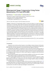
2. Parallel Encoding System of Video Image We are developing a parallel encoding system for video images. An outline of this system is shown in Fig. 1. In our system, the Grid environment is constructed of multiple PCs in a LAN setup and the video images are encoded in the system. The encoding process is as follows: (1) Send the uncompressed image to the Encoder PC. (2) Start the encoding process. (3) Reply a bitstream to the producer’s terminal and confirm the encoded image. For complex encoding that includes high-resolution P-frames and B-frames, high specification hardware is necessary. In this system, by separating the encoding process from the user’s terminal, real-time encoding can be achieved and the user can confirm the encoded movie during the encoding process.
3. Simple Encoding Method 3.1 Requirements An uncompressed image must be sent in step (1) in the process shown in Fig. 1. When the uncompressed image is directly sent, it places a serious burden on the LAN. Therefore, we decided that a simple compression method that does not place any burden on PC is needed. To achieve this, the following requirements are necessary: Frame Rate and Resolution Since an old PC can be used as the terminal PC, we assume that it has lower specifications. In addition, the CPU load for the simple compression should be as low as possible, because the decoding process is simultaneously driven in the terminal
㩿㪊㪀 㪩㪼㫇㫃㫐㩷㪸㫅㪻 㪚㫆㫅㪽㫀㫉㫄㪸㫋㫀㫆㫅
P C 㩷㪫㪼㫉㫄㫀㫅㪸㫃
㪜㫅㪺㫆㪻㪼㫉㩷䌐䌃 㩿㪉㪀 㪜㫅㪺㫆㪻㪼
㩿㪈㪀 㪪㪼㫅㪻㩷㫋㪿㪼 㪬㫅㪺㫆㫄㫇㫉㪼㫊㫊㪼㪻 㪠㫄㪸㪾㪼
㪜㫅㪺㫆㪻㪼㫉㩷䌐䌃
㪉㪇㪇㪇 㪈㪏㪇㪇 㪈㪍㪇㪇 㪈㪋㪇㪇 㪈㪉㪇㪇 㪈㪇㪇㪇 㪏㪇㪇 㪍㪇㪇 㪋㪇㪇 㪉㪇㪇 㪇
㪠㫄㪸㪾㪼㩷㪸 㪠㫄㪸㪾㪼㩷㪹 㪠㫄㪸㪾㪼㩷㪺 㪠㫄㪸㪾㪼㩷㪻
㪈
P C 㩷㪫㪼㫉㫄㫀㫅㪸㫃
LA N
㪉
㪊
㪋 㪌 㪍 㪎 㪏 㪚㫆㫄㫇㫉㪼㫊㫊㫀㫆㫅㩷㪣㪼㫍㪼㫃
㪐
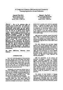
Fig. 2: The Encoding Time of a Frame for PNG
㪜㫅㪺㫆㪻㪼㫉㩷䌐䌃
㪜㫅㪺㫆㪻㪼㫉㩷䌐䌃
㪚㫆㫄㫇㫉㪼㫊㫊㫀㫆㫅㩷㫋㫀㫄㪼㩷㩿㫄㫊㪀
G rid
P C 㩷㪫㪼㫉㫄㫀㫅㪸㫃
Fig. 1: The Structure of the SYSTEM
PC. The standard home-use digital video camera has a ����� � pixels resolution, and the resolution of a DVD movie is �� � � � pixels. So, the required resolution of this system is assumed to be more than �� � � � pixels, and the required frame rate is assumed to be more than 30 frames/s in this research. Compression Ratio In this system, a high ratio compression, such as that for an MPEG, is not necessary because a transmission via a 100Mbps-1Gbps LAN is assumed. However, since a bit-rate of �� � � � pixels and a 30 frames/s uncompressed video image requires a 220-Mbps bandwidth, the network capacity of 100BASE-T is not sufficient enough to transmit the uncompressed image. The transmission of an uncompressed image weighs on the communications of other traffic. So, a fraction of the compression is necessary. In addition, it is desirable to be able to change the compression ratio according to the network performance. Degradation of Image Quality In this system, the video image is decoded and encoded after transmission to the encoder PC. In general, repetition of the encoding and decoding causes image quality degradation. So, a lossless compression is desirable in the compression process of this system. If necessary, a slight degradation in quality is permitted. However, a process with a serious amount of quality degradation must be avoided.
4. Traditional Method of Video Compression The most major standards of video coding are MPEG1[5], MPEG-2[6], MPEG-4[7], and H.264-AVC[8]. These methods need the large amount of processing time for DCT or Motion Prediction. JPEG[9] is the most famous coding standard for still image. JPEG is also using DCT as MPEG. So, JPEG is not suitable for this method as MPEG. PNG[10] is lossless encoding method for still image. This method spends the large amount of processing for LZ77, and a high CPU load is needed for efficient compression using filtering. For example, coding time of a frame for PNG is shown in Fig. 2. Fig.2is the result of encoding of �� � � � pixels image using LibPNG. Coding time is different with compression levels. The highest compression level 9 takes the time for 1-2 seconds, and the minimum compression level 1 takes the time about 100 ms. In PNG, since many coding time is needed for LZ77 and filtering, it is unsuitable for high-speed compression.
5. Simple Compression 5.1 The Data Flow of Simple Compression In this method, based on MPEG-2[6] encoding, some blocks are reduced. This reduction is necessary because motion estimation and DCT are a heavy load on a CPU. On the other hand, to use the similarity of neighboring frames, all the frames are divided into I-frames without inter-frame prediction and P-frames with inter-frame prediction. The frame sequence of the proposed method is shown in Fig. 3. As shown in Fig. 3, some P-frames are arranged after an I-frame. Each P-frame refers to the previous I-frame. The data flow of each frame is shown in Fig. 4. Our method is divided into "RGB�YUV transform", "Simple Difference", "RLE", and "Huffman Encoding". All of them are processed in P-frames. Only the "RGB�YUV transform", "RLE", and "Huffman Encoding" are processed in I-frames. The "Threshold Processing" is also processed if necessary.
when a normal RLE is executed for non-consecutive values. RLE, SRLE, Pack Bits, and RLE-� are some of the more well-known improvement methods. Since our past research has proved that Pack Bits is suitable for our method, Pack Bits is used in our method. In our method, the pixel values after "Simple Difference" � � � ��� � , �� ���� � , and �� � ��� � are scanned horizontally, and RLE byte streams � � , �� , and �� are generated.
䊶䊶䊶䊶䊶䊶䊶䊶䊶
I
P P P I
P P P
5.5 Huffman Encoding Fig. 3: Construction of Frames 8KFGQ &CVC
4)$ψ ��;78
㧙
6JTGUJQNF 2TQEGUUKPI�
㧾㧸㧱
'PEQFGF *WHHOCP ��&CVC 'PEQFKPI
(TCOG /GOQT[
Fig. 4: Data Flow of Simple Compression
5.2 RGB
YUV transform
An uncompressed video image of RGB format is transformed to YUV format. The YUV format is used for many standard video encoding. Since an RGB�YUV transformation places only a light load on the CPU and the number of data can be reduced by reducing the U element and the V element, the image data is transformed to the YUV format in the first step of our method.
5.3 Simple Difference Inter-frame prediction is used in our method to use the similarity of neighboring frames. We use the simple difference between the P-frame and the previous I-frame because the detection of a motion vector puts a large burden on the CPU load. "Simple Difference" is driven in the P-frames only. Let � � ��� � , � ���� � , � � ��� � be the �� �� � element pixel values of the P-frame at ��� � , and let � � � ��� � , �� ���� � , �� � ��� � be the �� �� � element pixel values of the previous I-frame at ��� � . The pixel values after "Simple Difference" �� � ��� � , �� ���� � , �� � ��� � are as follows:
� � � �� ���� � � �� � ��� � � � � �� �
� ���� � � ��� � � �� �
� � �� ���� � �� � ��� � � � �� �
The Huffman encoding is a kind of the entropy encoding. In the Huffman encoding, a Huffman tree is constructed from the data line, and a bit string is allocated to the data based on the Huffman tree. Huffman encoding is inferior in compression ratio in comparison with arithmetic coding[14], but is suitable for real-time processing because there is less computational complexity. There are two types of encoding for Huffman encoding[13], static Huffman encoding[12] and dynamic Huffman encoding. The former is the method for assigning a bit string after scanning and generating the Huffman tree. The latter is the method for assigning bits while generating the Huffman tree. The latter can generate a bit stream without finishing a scan of the whole data. However, because the CPU load is large, static Huffman encoding is used in our method. In our method, static Huffman encoding is processed to � � , �� , and �� , and bit streams � , � , and � are generated.
5.6 Improvement of compress ratio by using threshold processing Since there are cases where the method described in the previous section is insufficient for compressibility depending on the communication capacity of the LAN, it is desirable for it to be able to change the compression ratio according to the performance of the network. Some noise is included in an image. The compressibility can be improved by removing the noise, because it causes degradation in the encoding efficiency. The simplest (it does not add to the CPU load) technique is used to improve the compressibility in our method. Therefore, we use the threshold processing for Pframe method. In our method, the pixel values after "Threshold Processing" �� � ��� � , �� ���� � , and �� � ��� � are generated from �� � ��� � , �� ���� � , and �� � ��� � respectively by threshold processing.
(1)
5.4 RLE Run length encoding (RLE)[11] is a kind of lossless encoding. Some methods are proposed to deal with the problem of the number of encoded data greatly increasing
5.7 Compression Ratio and Processing Time The amount of encoded data in the I-frame and the Pframe of a YUV (4,4,4) format is shown in Fig.5. Two bars of PNG of Fig.5 is the minimum and maximum compression level respectively. Five movies of this experiment have the following feature.
YUV + Simple Difference 174.8ms
RLE 25.9m
Huffman Encoding 26.9ms
Others
˘ Total 縲A
8.2ms
331.8ms
㪧㫉㫆㫇㫆㫊㪼㪻㩷㪤㪼㫋㪿㫆㪻 㪫㪿㪼㩷㪘㫄㫆㫌㫅㫋㩷㫆㪽㩷㪛㪸㫋㪸 㩿㪢㪙㫐㫋㪼㫊㪀
Table 1: Compression Time of Proposed Method
㪊㪇㪇 㪉㪇㪇 㪈㪇㪇 㪇
From the above results, the following points are shown. 1)
2)
Since the amount of uncompressed data is 900 Kbytes, the compression ratio of the proposed method becomes ��� - ��� with the P-frame, and �� - ��� with the I-frame. These values are almost the same as the PNG format. In the highspeed LAN environment such as Gigabit Ether, this ratio of compression seems not to be a problem. However, in the low-speed or crowded network environment, the further improvement of the compression ratio may be needed. In that case, it is necessary to do the threshold processing. The Movie1, 3, and 5 had the high compression ratio of the P-frame compared with the I-frame. On the other hand, the difference to the compression ratio of the I-frame and the P-frame with the movie2 and movie4 was not seen. In video with few motions, this seems to be because the amount of information of the frame is reduced by simple difference.
About the P frame of the movie2, the average value of the encoding time of the proposed method was obtained by experiment. The encoding time of the proposed method with 2.8GHz Pentium(R) D CPU is shown in Table I. According to the experimental result, the average encoding time of one frame is a little more than 300 ms. This value is one case of implementation. But 30 frames per second can be attained in this implementation. According to the breakdown of the encoding time, more than half was RGBYUV conversion and simple difference. Among them, it is thought that the RGB-YUV conversion which needs a floating point operation occupies the most part of processing time. But this process can be omitted when the input video format is a YUV format. Presently, most of commercially available video camera support the YUV format as video output. Moreover, since the parallelization using multi-cores etc. are possible in simple difference, it seems to be possible to add a more complicated encoding method by the further improvement in the speed.
㪧㪥㪞㩿㪤㪸㫏㫀㫄㫌㫄㪀
㪋㪇㪇
¯
㪤㫆㫍㫀㪼㪈
㪤㫆㫍㫀㪼㪉
㪤㫆㫍㫀㪼㪊
㪤㫆㫍㫀㪼㪋
㪤㫆㫍㫀㪼㪌
(a) I-frame 㪧㫉㫆㫇㫆㫊㪼㪻㩷㪤㪼㫋㪿㫆㪻 㪫㪿㪼㩷㪘㫄㫆㫌㫅㫋㩷㫆㪽㩷㪛㪸㫋㪸 㩿㪢㪙㫐㫋㪼㫊㪀
Movie1 and Movie5 are the sequence of the almost same frames. ¯ In Movie2, the entire frame is moving horizontally. ¯ In Movie3, there is almost no change in the screen itself, and the person in a screen is moving the head. ¯ Movie4 is the image which had a camera in the hand, and the camera shake occurs in the entire frame.
㪧㪥㪞㩿㪤㫀㫅㫀㫄㫌㫄㪀
㪌㪇㪇
㪧㪥㪞㩿㪤㫀㫅㫀㫄㫌㫄㪀
㪧㪥㪞㩿㪤㪸㫏㫀㫄㫌㫄㪀
㪌㪇㪇 㪋㪇㪇 㪊㪇㪇 㪉㪇㪇 㪈㪇㪇 㪇
㪤㫆㫍㫀㪼㪈
㪤㫆㫍㫀㪼㪉
㪤㫆㫍㫀㪼㪊
㪤㫆㫍㫀㪼㪋
㪤㫆㫍㫀㪼㪌
(b) P-frame Fig. 5: The Amount of Compressed Data
6. The Use of Motion Vector In the system mentioned in section II, since the motion vector is generated when the encoding process is done at Encoder PC, it is sent to and used in the terminal. Concretely, difference processing which used the motion vector from Encoder PC is done instead of "Simple Difference". However, in order to perform difference processing of next frame based on the returned motion vector, it is necessary to predict the motion vector for next frame. For example, it is assumed that frames of the video image are arranged as one I-frame, � � B-frames, one P-frame, � � B-frames, one P-frame... as shown in Fig.6. In such case, encoding of the first I frame (frame-0) is done at first. Secondly, encoding of the next P frame (frame-�) is done. In this time, the motion vector between the frame-� and the frame-� is generated. By using this motion vector, the motion vectors of succession frames are predicted and difference processing in the simple compression of them is done. In this case, the B frame from the frame 1 to the frame-� � is sent firstly. Next, frames are sent in order the P frame of frame-��, the B frames from frame-� � � to frame-�� �... Then, the motion vectors of these frames are predicted. As a method for predicting the motion vector of frame- based on the motion vector between the frame-0 and frame�, the following two predictor can be considered. The example of our method is shown in Fig.7. At first, When Frame-� (The second encoding frame of MPEG) is encoded, the motion vector of Frame-n is generated. Then the motion vector of Frame-� is sent to terminal, and it is used in the Simple Compression of next encoding frames �). At the terminal, by using motion (Frame-1,2,3...� vector, Simple Compression is done.
䊶䊶䊶䊶䊶䊶䊶䊶䊶
䊶䊶䊶䊶䊶䊶䊶䊶䊶
I
B B B
P B B B
Fig. 6: Frames of MPEG encoding E n c o d e r S e rv e r
1 3 ) B y u s in g m o tio n v e c to r, S im p le C o m p re s s io n is d o n e .
LA N 0
n
1 ) W h e n F ra m e -n is e n c o d e d , th e m o tio n v e c to r o f F ra m e -n is g e n e ra te d .
2 ) T h e m o tio n v e c to r o f F ra m e n is s e n t to te rm in a l, a n d it is Te rm in a l u s e d in th e S im p le C o m p re s s io n o f F ra m e -1 ,2 ,3 ...
Fig. 7: The Example of the Use of Motion Vector
¯
Predictor A: It assumes that the object or the frame itself is moving as linear uniform motion. Then the predicted motion � � � � is as follows: vector of frame- �
�� � � �
¯
��
� �� �
(2)
Predictor B: The motion search using block matching algorithm may not reflect a motion correctly. Then, assuming that it does not have change in a motion with each frame, � � � �� is the predicted motion vector of frame- � assumed as follows:
�� � �� �� �
�
(3)
In our method, the difference error of both the predictor A and the predictor B are calculated for every macroblock, and results with fewer errors are chosen for every macroblock. Thereby, since the amount of information decreases compared with simple difference, it is expected that a compression ratio will improve.
7. Performance Evaluation 7.1 Experimental Method To evaluate the performance of the proposed method, 30 types of movies were encoded by using the simple compression. The experimental movies are used from standard
images by the Institute of Image Information and Television Engineers (ITE). These movies are 24 bit full-color images at � � ��� pixels. For these movies, P-frame encoding (the encoding that is include for the simple difference) are processed and evaluated. In this experiment, we compared the amount of data of simple difference and the proposed method using the motion vector between the frame-0 and frame-1 from MPEG-4 encoder. In this experiment, we experimented by using Iframe and P-frame. Only the first frame (frame-0) is Iframe, and from frame-1 to frame-3 are P-frame respectively. Among them, simple compression by the method shown in section 4 was performed at frame-2 and the frame-3 , and the amount of compressed data was compared.
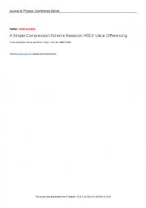
7.2 Experimental Results The results of our compression algorithm of 30 movies without and with motion vector are shown in Fig. 8 and Fig. 9. The result of frame-2 is shown in Fig. 8, and the result of frame-3 is shown in Fig. 9. In both of the compression for frame-2 and frame-3, the difference with frame-0 is used. Because the distance from frame-0 to frame-3 is longer than the distance to frame-2, the amount of compressed data for frame-3 become larger than frame-2. As shown in those figures, the amounts of compressed data become from 40 Kbytes to 140 Kbytes. The amounts of data of uncompressed data for those images are about 225 Kbytes. So the compression ratio becomes about from � � to ��. Also, � �� maximum and � �� average of the data amount were reduced by using motion vector. The picture which has much (11SIF) and little (17SIF) influence by use of a motion vector of those images are shown in Fig.10 and Fig.11. In Fig.10, the whole image flows from right to left. And in Fig.11, the tree is shaking by the wind. The picture which moves smoothly as Fig.10 has much influence by using motion vector. The amount of compressed data of each frame with and without motion vector are shown in Fig.12 and Fig.13. However, since "With MV" in Frame-1 uses the motion vector between Frame0 and Frame-1, it cannot realize simple compression with motion vector in fact. The values of Frame-1 in those figures are only shown as reference values. In both figures, the amount of compressed data becomes large as distance with the Frame-0 becomes long. This is because the difference in a picture becomes large as frame distance becomes long. Also, any frame shows the same tendency in the following point, and it turns out that this technique is effective regardless of frame distance. ¯ In 11SIF, the amount of compressed data is sharply reduced by use of motion vector. ¯ In 17SIF, there are few effects by use of motion vector, and the difference in the amount of the data of the both method is not seen.
㪈㪋㪇㪃㪇㪇㪇 㪈㪉㪇㪃㪇㪇㪇 㪈㪇㪇㪃㪇㪇㪇
㪮㫀㫋㪿㫆㫌㫋㩷㪤㪭 㪮㫀㫋㪿㩷㪤㪭
㪏㪇㪃㪇㪇㪇 㪍㪇㪃㪇㪇㪇 㪋㪇㪃㪇㪇㪇 㪉㪇㪃㪇㪇㪇 㪇 㪈 㪈 㪪 㪠 㪝
㪈 㪉 㪪 㪠 㪝
㪈 㪊 㪪 㪠 㪝
㪈 㪋 㪪 㪠 㪝
㪈㪋㪇㪃㪇㪇㪇 㪈㪉㪇㪃㪇㪇㪇 㪈㪇㪇㪃㪇㪇㪇
㪮㫀㫋㪿㫆㫌㫋㩷㪤㪭 㪮㫀㫋㪿㩷㪤㪭
㪏㪇㪃㪇㪇㪇 㪍㪇㪃㪇㪇㪇 㪋㪇㪃㪇㪇㪇 㪉㪇㪃㪇㪇㪇 㪇
㪈 㪌 㪪 㪠 㪝
㪈㪍㪇㪃㪇㪇㪇
㪈 㪉 㪊 㪌 㪍 㪎 㪏 㪐 㪈 㪪 㪪 㪪 㪪 㪪 㪪 㪪 㪪 㪇 㪠 㪠 㪠 㪠 㪠 㪠 㪠 㪠 㪪 㪝 㪝 㪝 㪝 㪝 㪝 㪝 㪝 㪠 㪝
㪈 㪈 㪪 㪠 㪝
㪈 㪉 㪪 㪠 㪝
㪈 㪊 㪪 㪠 㪝
㪈 㪋 㪪 㪠 㪝
㪈 㪌 㪪 㪠 㪝
㪉 㪋 㪪 㪠 㪝
㪉 㪌 㪪 㪠 㪝
㪉 㪍 㪪 㪠 㪝
㪉 㪎 㪪 㪠 㪝
㪉 㪏 㪪 㪠 㪝
㪉 㪐 㪪 㪠 㪝
㪈㪍㪇㪃㪇㪇㪇 㪥㫌㫄㪹㪼㫉㩷㫆㪽㩷㪜㫅㪺㫆㪻㪼㪻㩷㪛㪸㫋㪸㩷㩿㪙㫐㫋㪼㫊㪀
㪥㫌㫄㪹㪼㫉㩷㫆㪽㩷㪜㫅㪺㫆㪻㪼㪻㩷㪛㪸㫋㪸㩷㩿㪙㫐㫋㪼㫊㪀
㪈 㪉 㪊 㪌 㪍 㪎 㪏 㪐 㪈 㪪 㪪 㪪 㪪 㪪 㪪 㪪 㪪 㪇 㪠 㪠 㪠 㪠 㪠 㪠 㪠 㪠 㪪 㪝 㪝 㪝 㪝 㪝 㪝 㪝 㪝 㪠 㪝
㪥㫌㫄㪹㪼㫉㩷㫆㪽㩷㪜㫅㪺㫆㪻㪼㪻㩷㪛㪸㫋㪸㩷㩿㪙㫐㫋㪼㫊㪀
㪥㫌㫄㪹㪼㫉㩷㫆㪽㩷㪜㫅㪺㫆㪻㪼㪻㩷㪛㪸㫋㪸㩷㩿㪙㫐㫋㪼㫊㪀
㪈㪍㪇㪃㪇㪇㪇
㪈㪍㪇㪃㪇㪇㪇
㪈㪋㪇㪃㪇㪇㪇 㪈㪉㪇㪃㪇㪇㪇 㪈㪇㪇㪃㪇㪇㪇 㪏㪇㪃㪇㪇㪇 㪍㪇㪃㪇㪇㪇 㪋㪇㪃㪇㪇㪇 㪉㪇㪃㪇㪇㪇 㪇 㪈 㪍 㪪 㪠 㪝
㪈 㪎 㪪 㪠 㪝
㪈 㪏 㪪 㪠 㪝
㪈 㪐 㪪 㪠 㪝
㪉 㪇 㪪 㪠 㪝
㪉 㪈 㪪 㪠 㪝
㪉 㪉 㪪 㪠 㪝
㪉 㪊 㪪 㪠 㪝
㪉 㪋 㪪 㪠 㪝
㪉 㪌 㪪 㪠 㪝
㪉 㪍 㪪 㪠 㪝
㪉 㪎 㪪 㪠 㪝
㪉 㪏 㪪 㪠 㪝
㪉 㪐 㪪 㪠 㪝
㪊 㪇 㪪 㪠 㪝
Fig. 8: Experimental Result (Frame-2)
8. Conclusion In this paper, we presented a simple compression method that can be transmitted via a LAN and we proposed the improved method by using motion vector from video encoder. In this method, difference processing using the motion vector from encoder PC is performed instead of simple difference. Also, the results of our performance evaluation were presented. As a result from some experimentation, � �� maximum and � �� average of the data amount were reduced by using motion vector. It is thought that it requires some processing time by execution of this method. But by the reduction of the unnecessary processing such as RGB-YVU conversion and the use of the parallel processing of CPU, etc, it seems that real time processing becomes possible. As the future work, to evaluate the processing time of proposed method is remained.
References [1] Windows Media Encoder: http://www.microsoft.com/japan/windows/windowsmedia [2] Adobe Premiere: http://www.adobe.com/jp/products/premiere/ [3] Fixstars CodecSys: http://www.fixstars.com/products/codecsys/
㪈㪋㪇㪃㪇㪇㪇 㪈㪉㪇㪃㪇㪇㪇 㪈㪇㪇㪃㪇㪇㪇 㪏㪇㪃㪇㪇㪇 㪍㪇㪃㪇㪇㪇 㪋㪇㪃㪇㪇㪇 㪉㪇㪃㪇㪇㪇 㪇 㪈 㪍 㪪 㪠 㪝
㪈 㪎 㪪 㪠 㪝
㪈 㪏 㪪 㪠 㪝
㪈 㪐 㪪 㪠 㪝
㪉 㪇 㪪 㪠 㪝
㪉 㪈 㪪 㪠 㪝
㪉 㪉 㪪 㪠 㪝
㪉 㪊 㪪 㪠 㪝
㪊 㪇 㪪 㪠 㪝
Fig. 9: Experimental Result (Frame-3)
[4] Y.Miura, Shogo Yamato, Simple Compression Method for Parallel Encoding Environment of Video Image, Proc.of 2009 IEEE Pacific Rim Conference on Communications Computers and Signal Processing (PACRIM 2009), 2009. [5] ISO/IEC 11172, Coding of moving pictures and associated audio for digital storage media at up to about 1,5 Mbit/s, 1991. [6] ISO/IEC 13818, Generic coding of moving pictures and associated audio information, 1994. [7] ISO/IEC 14496, Final Draft International Standard MPEG-4, 1998. [8] ISO/IEC 14496-10, Final Draft International Standard MPEG-4 Part 10 哂 dvanced Video Coding, 2004. [9] ISO/IEC 10918-1:Information technology – Digital compression and coding of continuous-tone still images, 1994. [10] Information technology – Computer graphics and image processing – Portable Network Graphics (PNG): Functional specification, 2004 [11] J. Capon, "A Probabilistic Model for Run-Length Coding of Pictures", IRE Trans. Inform. Theory, Vol.5, No.5, pp.157-163, 1959. [12] D. A. Huffman, "A method for the construction of minimumredundancy codes", Proceedings of the I.R.E., Sept. 1952, pp. 10981102. [13] N. Faller, "An Adaptive System for Data Compression", Record of the 7th Asilomar Conference on Circuits, Systems and Computers, pp.593597, 1973. [14] Ian H. Witten, Radford M. Neal, and John G. Cleary, "Arithmetic Coding for Data Compression", Communications of the ACM, Vol.30, No.6, pp.520-540, 1987.
a) Frame-0
a) Frame-0
b) Frame-3 Fig. 11: Experimental Image (17SIF)
㪥㫌㫄㪹㪼㫉㩷㫆㪽㩷㪜㫅㪺㫆㪻㪼㪻㩷㪛㪸㫋㪸㩷㩿㪙㫐㫋㪼㫊㪀
㪈㪋㪇㪃㪇㪇㪇 㪈㪉㪇㪃㪇㪇㪇 㪈㪇㪇㪃㪇㪇㪇 㪏㪇㪃㪇㪇㪇 㪮㫀㫋㪿㫆㫌㫋㩷㪤㪭
㪍㪇㪃㪇㪇㪇
㪮㫀㫋㪿㩷㪤㪭
㪋㪇㪃㪇㪇㪇 㪉㪇㪃㪇㪇㪇
b) Frame-3
㪇 㪝㫉㪸㫄㪼㪄㪈
㪝㫉㪸㫄㪼㪄㪉
㪝㫉㪸㫄㪼㪄㪊
Fig. 10: Experimental Image (11SIF) Fig. 12: Experimental Result (11SIF) 㪥㫌㫄㪹㪼㫉㩷㫆㪽㩷㪜㫅㪺㫆㪻㪼㪻㩷㪛㪸㫋㪸㩷㩿㪙㫐㫋㪼㫊㪀
㪈㪋㪇㪃㪇㪇㪇 㪈㪉㪇㪃㪇㪇㪇 㪈㪇㪇㪃㪇㪇㪇 㪏㪇㪃㪇㪇㪇
㪮㫀㫋㪿㫆㫌㫋㩷㪤㪭 㪮㫀㫋㪿㩷㪤㪭
㪍㪇㪃㪇㪇㪇 㪋㪇㪃㪇㪇㪇 㪉㪇㪃㪇㪇㪇 㪇 㪝㫉㪸㫄㪼㪄㪈
㪝㫉㪸㫄㪼㪄㪉
㪝㫉㪸㫄㪼㪄㪊
Fig. 13: Experimental Result (17SIF)