1062
IEEE JOURNAL OF SOLID-STATE CIRCUITS, VOL. 41, NO. 5, MAY 2006
A Simple On-Chip Repetitive Sampling Setup for the Quantification of Substrate Noise Michiel De Wilde, Wim Meeus, Pieter Rombouts, Member, IEEE, and Jan Van Campenhout, Member, IEEE
Abstract—The quantification of substrate noise is an important issue in mixed-signal designs, where sensitive analog circuits are embedded in a hostile digital environment. In this paper we present an experimental environment to characterize the sensitivity of embedded analog circuits to digitally generated substrate noise. Our measurement technique is based on equivalent-time substrate voltage sampling and uses a simple differential latch comparator without explicit input sample-and-hold. A surprisingly large measurement bandwidth is observed, which is explained from the detailed circuit behavior. On our 0.18- m CMOS test chip, we have demonstrated that our system allows to wavetrace pulses as narrow as 200 ps accurately. Additionally, the extraction of precise measurement data from observations that are excessively corrupted by additive noise and timing jitter is addressed. We present simple yet very effective methods to accurately reconstruct pulse waveform features without the use of delicate deconvolution operations. Index Terms—CMOS integrated circuits, differential amplifiers, integrated circuit noise, jitter.
I. INTRODUCTION N MIXED-SIGNAL designs, where sensitive analog circuits are embedded alongside fast digital circuits, substrate coupling of digital circuit noise can severely compromise the analog behavior. Careful separation of both circuits at the circuit and layout levels—using highly decoupled separate power and ground nets and a layout with minimal coupling between sensitive metal tracks—leaves only coupling through the conductive substrate as the remaining noise mechanism. Unless costly triple-well CMOS technology is applied, this coupling cannot be eliminated completely. The prediction of substrate currents and the resulting bulk potential variations and ground bounce, and the design of noise-tolerant circuits are active research topics [1]–[4]. In this paper, we report on a measurement technique for very fast periodic bulk potential variations. The approach was applied in a test chip for embedded optical interconnect [5], where we need to quantify the robustness of sensitive optical receiver circuits to substrate noise. To this end, we have designed controllable substrate noise generation circuits and modeled the substrate coupling using Cadence’s SubstrateStorm software [6].
I
Manuscript received June 29, 2005; revised November 15, 2005. This work was supported in part by the European Commission’s FP5 IST program (project IST-2000–28358), the Belgian Research Foundation–Flanders (project G.0475. 05), and the PHOTON Interuniversity Attraction Poles program (IAP V/18), initiated by the Belgian State, Prime Minister’s Service, Science Policy Office. The authors are with the Department of Electronics and Information Systems (ELIS), Ghent University, B-9000 Gent, Belgium (e-mail: Michiel.
[email protected];
[email protected];
[email protected];
[email protected]). Digital Object Identifier 10.1109/JSSC.2006.872873
Our measurement circuit for fast substrate noise has been integrated alongside the noise generation circuits as a means to validate the substrate model through direct measurement. The measurement circuit is analyzed and a surprisingly small sampling window with a correspondingly large effective bandwidth are observed. Furthermore, a new and efficient technique was developed to accurately extract the width, the position and the top of pulses from measurement data deeply buried in jitter noise. The proposed technique is simple and does not require numerically delicate deconvolution operations. Our approach is based on the equivalent time measurement technique [7]–[10] and hence is applicable when the generated noise is periodic. Here, the substrate signal is sampled at different phases in subsequent periods. Each sample is compared to an adjustable reference voltage using a latch comparator. By adapting the reference voltage for each value of the sampling delay, the waveform of the signal can be reconstructed. The result of the comparison is observable at a standard digital I/O pad, obviating the need for high-bandwidth analog I/O. The repetitive sampling principle has far wider applicability than substrate noise measurements, and most results will apply to the measurement of any reproducible signal. This paper is structured as follows. In Section II, we briefly discuss the causes and effects of substrate noise, the noise measurement principle, previous work and the contributions of this paper. Next, the measurement circuit is presented. The following sections take a closer look at the properties of the latch comparator. In Section III, the dynamic behavior of the circuit is studied, and in Section IV we investigate measurement inaccuracies resulting from a noisy voltage reference or sampling time jitter. Finally, in Section V, we report on the good agreement between measured and simulated substrate disturbances and on the performance of our noise elimination technique. Section VI concludes the paper. II. PROBLEM DEFINITION AND PREVIOUS WORK A. Substrate Noise The term substrate noise comprises all effects caused by the switching of digital circuit nodes, which change the bulk potential underneath sensitive devices of the analog circuit, or inject current into substrate contacts. There are several sources of substrate noise. The most important reported direct causes [2], [3], [11] are capacitive coupling from MOSFET source and drain nodes and impact ionization from the MOSFET channel—a carrier generation process where highly energetic carriers collide with the crystal lattice—which inject current into the substrate. The effect on the substrate is characterized by short, sharp pulses occurring nearly simultaneously with the switching events that
0018-9200/$20.00 © 2006 IEEE
DE WILDE et al.: A SIMPLE ON-CHIP REPETITIVE SAMPLING SETUP FOR THE QUANTIFICATION OF SUBSTRATE NOISE
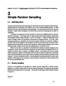
Fig. 1. Observed direct and indirect substrate disturbance waveforms. Note the large bandwidth differences between both effects.
1063
vide better noise isolation than EPI substrates, as guard ring structures are far more effective [11]. Several tools exist for the extraction and simplification of the equivalent RC network; we have used Cadence’s SubstrateStorm for this purpose [6]. The extraction and simplification of the equivalent network from a digital circuit with many substrate connections is a tedious and computationally complex task, which quickly runs into long computation times as circuit complexity increases. In this respect, the availability of small embedded measurement circuitry is a useful complement to pure simulation. In an attempt to predict the experimental results to validate the measurement technique, we have simultaneously modeled a configurable noise generation circuit together with our measurement circuit. B. Measuring Fast Substrate Signals
cause them. Substrate voltage transients have very specific properties: the voltages typically take values in an interval of only some tens of mV around the off-chip reference ground, and the output impedance of a floating bulk contact is relatively high [11]. The bulk voltage instantaneously affects the threshold voltage of the involved MOSFETs, and capacitive coupling with various circuits nodes is omnipresent. A major indirect cause of substrate disturbances originates from the power supply system and is known as ringing. When an external point on a PCB ground plane close to the IC is used as a common reference for the separate analog and digital power distribution, the digital on-chip power and ground lines will exhibit voltage oscillations with respect to this point, and hence with respect to the analog ground system. These oscillations are caused by the sharp supply and ground current fluctuations injected into the power system. This system consists of an RLC resonator composed of the on-chip decoupling capacitance, and the inductance and resistance of the digital power and ground lines (bondwires). Even when digital and analog ground lines are kept fully separate on-chip, there exists a relatively low-impedance path between them through the substrate, because they contact the same p-bulk in very many places—e.g., at least once in each digital cell. Hence, the ringing of the digital power system is coupled to the on-chip analog ground reference, disturbing the analog circuitry. The frequency behavior of ringing is quite distinct from the effects from the direct causes (Fig. 1), in that the observed frequencies range between 50 and 500 MHz whereas direct substrate noise has frequency components in the gigahertz range. In the literature, most attention goes to the effects of ringing. Indeed, the ringing effect is larger in amplitude and time scale than the direct effect and considerable effort has been invested in neutralizing its effects [2]. The ringing effect is much less apparent when packaging parasitics are reduced, for instance when the IC is being flip-chipped instead of wirebonded [4]. In our work, we address the direct substrate disturbances, which are far more difficult to measure than the effects caused by ringing because they require a much higher measurement bandwidth. We consider bulk-type (lowly doped) substrates, which are quite common in modern technologies. They have fairly high resistivity and cannot be considered equipotential; hence they must be modeled as a three-dimensional RC network. They pro-
Substrate voltage wavetracing has never been straightforward: direct electrical on-chip probing is generally impossible, and in addition the inductance and large capacitive load of a single-ended external probe disrupt the signal. In an indirect approach, substrate noise has been measured through its impact on the threshold voltage of a single MOSFET [11]. The bandwidth of this method is severely limited by probing parasitics. Integration of a fast wideband analog amplifier and bonding out the amplifier output is another technique [2], [4], which however requires the use of very high-bandwidth analog output pads. On-chip real-time sampling of signals that vary with the achievable speed of the used IC technology is infeasible with circuits of the same technology: either the sampling circuits need to take samples impossibly fast, or a very large number of parallel sampling circuits would be required. Furthermore, a very large bandwidth to store the measurement data or to bring them off-chip is required. However, if the longer acquisition time is no problem and if the signals are periodic, equivalent time sampling measurements using on-chip voltage comparators constitute a simple and low-cost alternative. Sampling can be done over subsequent instances of the signal, with only one sampling circuit. The phase between the periodic waveform and the sampling time is made adjustable by on-chip or external means, in order to gather samples throughout the whole signal period. Repetitive sampling also eliminates the need for analog-to-digital conversion as a simple, but repeated on-chip comparison with an externally provided analog voltage will suffice. The result of the comparison is a low-bandwidth binary signal. There is no restriction on the complexity or duration of the repetitive experiment as long as the repetitions are accurate and deterministic (see Casper et al. [10] who used a full pseudorandom digital pattern as stimulus in one repetitive experiment). Makie-Fukuda et al. have used chopper-type single-ended voltage comparators [7] to sample substrate voltages in equivalent time. The single-ended nature of this circuit makes the comparison itself vulnerable to MOSFET threshold variations and power supply ringing. A differential and more robust approach was taken by Nagata et al., where differential latch comparators are employed [9]. A latch comparator is a circuit that
1064
IEEE JOURNAL OF SOLID-STATE CIRCUITS, VOL. 41, NO. 5, MAY 2006
III. ESTIMATING BANDWIDTH AND LINEARITY OF THE LATCH COMPARATOR
Fig. 2. Circuit diagram of the latch comparator used in our measurement circuit.
performs a clocked comparison of two voltages. Such circuits are widely deployed in A/D converters [12]–[14] and dynamic RAM circuits [15]. Latch comparators have also been applied successfully for on-chip sampling of other signals for diagnostic purposes, e.g., to verify the timing of a SRAM circuit [8] or to monitor the eye diagram of a communication link [10]. Our experimental setup was inspired by Nagata et al. [9]. However, our approach is different from theirs as we aim at observing the fast direct substrate noise effect instead of the ringing. Where there was plenty of measurement bandwidth for the observation of ringing, now the bandwidth of the examined signals becomes much higher. Hence, analyzes of the intrinsic measurement bandwidth and the effects of additive noise and jitter were considered essential. Observing the direct substrate noise in high-resistive substrates also requires full control over the relative location of noise sources and detectors, while in EPI-type substrates, distances of more than about 4 times the thickness of the epitaxial layer are considered to exhibit equal noise coupling [11]. Our noise generation circuit provides very localized substrate noise sources, and the location of our detector circuit is judiciously chosen. The detector itself is very simple: it requires only one comparison voltage and only one measurement trigger clock. Fig. 2 shows the circuit diagram. The measurement bandwidth is surprisingly large and does not, as is commonly believed, depend on the time constant of the regenerative latch. The latch comparator is modeled after the sense amplifier design for the memory cells of the StrongArm microcontroller [15]. It essentially consists of a bistable cross-coupled latch (transistors to ) fed by a differential stage consisting of transistors to . When sampling, the latch is released from its metastable state with an initial imbalance resulting from the differential stage. This imbalance reflects the difference between the reference voltage and the substrate signal; the sign of the difference will cause the latch to move to the corresponding stable state.
Let us now take a closer look at the behavior of the latch comparator aiming at a more precise characterization of its bandwidth properties. In equivalent time sampling measurements, usually a sample/hold circuit is used to capture the signal to be measured. The sampling circuits used are linear circuits with very good approximation, and their equivalent bandwidth is determined by their aperture time, i.e., the time window during which the signal is observed and somehow averaged to provide a single sample value. In our system, no explicit sample/hold circuit is deployed. However, it is obvious that during a brief period immediately following a positive clock transition, the input signal is observed and compared to the reference value, causing the latch to move to its final state. Consequently, a sampling function similar to the explicit ones found in traditional circuits must be present. It is much less obvious to find out whether the ensuing sampling action can be considered a linear operation, and if so, to determine its equivalent bandwidth. Indeed, during operation, all transistors operate in their large signal regime, where there exists no simple linear relationship between e.g., the gate voltage and drain current of a FET. Hence, a more detailed analysis is called for. a) Bandwidth: Fig. 3 shows the simulated operation of the circuit when an input voltage is sampled, and where the reference voltage is set to a value that releases the latch very close to its metastable operating point. This is the situation we achieve in noise-free conditions when the measurement outcome contains 50% 1’s and 50% 0’s. From the time behavior of the circuit, the sampling operation can be inferred. Initially, when the clock is switched off, and the drains of input is still low, transistor and are all pulled high. Node assumes an transistors intermediate voltage slightly below . When the clock signal starts conducting, pulling rises above threshold (epoch ), low. At the same time, the negathe common source node induces a negative transition on tive transition on node due to capacitive coupling and the fact that the gate of is coupled to the high-ohmic substrate (voltage kickback). In our case, we assume that this kickback effect is signal-independent and hence will result in an overall offset. has dropped below the gate At time , when node and , respectively, a drain current starts to voltages of flow in these transistors. This current discharges the respective and , bringing them low. The discharge rates drain nodes are proportional to the respective drain currents, which, in turn depend on the instantaneous gate-to-source voltages of the tranand . sistors and Due to the differences between the gate voltages of , the nodes and are discharged at a different rate, and a voltage difference builds up between them. At time , when both nodes have dropped sufficiently low, the transistors , , , start conducting, activating the positive feedand later back loop of the latch, which will exponentially move to a stable state corresponding to the initial voltage difference on nodes and . As already mentioned, during actual measurements the reference voltage is adjusted until this initial voltage difference
DE WILDE et al.: A SIMPLE ON-CHIP REPETITIVE SAMPLING SETUP FOR THE QUANTIFICATION OF SUBSTRATE NOISE
1065
Fig. 3. (a) Substrate and reference connections of the measurement circuit, simplified for our empirical analysis. (b) Simulated operation of the latch comparator. The voltage V was chosen such that the latch was released very close to its metastable equilibrium point. Note that the voltage V undergoes a marked voltage drop during the measurement, due to capacitive voltage kickback from node N into the finite substrate impedance. The actual substrate signal to be measured is superposed onto V and is not discernable on the scale of the figure.
is as small as possible, releasing the latch as close as possible to its metastable operating point. Hence, the measurement value is the specific value of the reference voltage which leads to as small as possible a voltage difand at time , and the actual ference between nodes buildup of this difference (i.e., the period during which the input and the reference are compared) takes place between and . , which determines This results in a sampling period the equivalent bandwidth of the measurement. As can be seen in Fig. 3(b), this sampling window can be much smaller than the regeneration time of the latch. b) Linearity: The question remains as to whether the equivalent relationship between the input voltage and the measurement result is linear or sufficiently close to linear, so that accurate waveform measurements can be performed. To investigate this question, we use a semi-empirical approach, inspired by the simulation of Fig. 3(b). Hereto, we determine the incremental effect of the small substrate signal when observed during the measurement operation. We model the difference in of and during the sampling of a the drain currents sinusoidal waveform , which represents the net incremental effect of the substrate voltage onto the gate . is a small amplitude (e.g., 10 mV), typical of direct of substrate disturbances. We set the time origin to epoch and approximate the relevant node voltages by (1) (2) (3) is the DC-bias of the gate of and the last term in where (1) approximately represents the voltage kickback onto the gate , clearly visible in Fig. 3(b). Equation (3) approximates of the downward transition of the common source voltage at node from the point where starts conducting. The rate repand was resents the time constant in the transition of node extracted from the simulation result of Fig. 3(b). These waveforms are simple approximations, but are chosen such that they
allow symbolic manipulation of the equations. For our analysis we assume a simple transistor model, in which the drain current . of a FET in its saturation region is proportional to The results of our analysis are essentially independent of the de, tailed FET characteristics or the precise waveforms of and because we only need to consider small deviations from the actual voltage trajectories rather than the trajectories themselves. Therefore, any more sophisticated model will lead to the same qualitative conclusions. Using these definitions and assumptions, we obtain (4) and the resulting voltage difference between is proportional to
and
at time
(5) We now set in (5), and solve this equation for symbolically.1 The complicated expression for thus obtained represents the measurement outcome, and its dependence on the amplitude , frequency and phase of the input signal will reflect the linearity or the lack thereof. A perfectly having the form linear response should result in . The value of where is the equivalent 3-dB bandwidth of the circuit. The actual expression obtained is however much more complicated. To estimate the degree of nonlinearity, we have expanded into a Taylor series w.r.t. , and for each value of we have computed the maximal value of the second order term for varying . Numerical values were chosen according to Fig. 3: mV, mV, mV, ps, and ps. Fig. 4(a) shows a Bode plot of and the maximal value of the second order term, for a signal amplitude 1This was done using Maplesoft’s Maple 9.5 suite. Although results were obtained in closed form, they are far too complex to be shown explicitly.
1066
IEEE JOURNAL OF SOLID-STATE CIRCUITS, VOL. 41, NO. 5, MAY 2006
Fig. 4. Amplitude response of the latch comparator. (a) The response and its second order term based on our empirical analysis (V = 0:1 Volt). (b) Obtained through simulation of the circuit with sinusoidal input.
mV. The 3-dB bandwidth is roughly 25 GHz, and the second-order term initially stays more than 70 dB below the signal, reducing to 38 dB at 25 GHz. The circuit’s frequency response was also directly obtained from a simulation run. To this end, transient simulations were performed with a sinusoidal input with a 10-mV amplitude. For each frequency, the sampling phase was set to five equally spaced values in the period and the was determined. Through the five results, metastable a sine wave was fitted, yielding the amplitude and the phase of the response. The resulting Bode plot is shown in Fig. 4(b). As both the bandwidth and the first notch depend on the sampling time, we can conclude that the estimate of from our empirical circuit analysis provides a very good fit. Furthermore, even at input amplitudes as large as 100 mV, the second-order term is still 18 dB below the first order term over the entire bandwidth. Hence, we can conclude that our circuit, despite the lack of sample/hold circuits, is linear with good approximation in the amplitude range for our purpose and has excellent bandwidth. IV. MEASURING IN THE PRESENCE OF JITTER AND ADDITIVE NOISE We now address the problem where we intend to measure the sharp, isolated pulses caused by capacitively coupled substrate events, but where the horizontal time base is subject to significant time jitter. It is well known that timing jitter can drastically obscure the real pulse shape in equivalent time measurements, and should be eliminated. Several authors [16]–[19] have presented methods to eliminate both the jitter and additive-noise effects from measurements, under various hypotheses about the true waveform and the statistical properties of the noise components. However, all approaches assume that the raw measurement result is an analog value, corrupted by both noise components, for each sampling instant. In our measurement system, raw measurement data are binary (1’s and 0’s), and indicate the result of the individual compar. As isons of the substrate signal with the analog voltage indicated in the previous section, when we want to measure the to a value which yields a instantaneous signal value, we set 50–50% result on the comparison; this value then represents the analog value of the measurement. Setting other values for
will yield other relative outcomes of the comparison. In noisefree conditions, the change-over from a 0–100% to a 100–0% is immediate, while in our test setup, in nearly noise-free conditions, the change-over occurs in a very narrow interval (less than one mV). In these conditions, with sharp transitions, a fast to a 50–50% outcome simple time scan with adjustment of (e.g., using successive approximations) will provide an accurate measurement result. In the presence of both timing jitter and additive noise, the change-over interval broadens and the 50% percentile is no longer a good approximation of the true waveform. Performing a repeated measurement at time delay , with a fixed value of yields a fraction of 1’s denoted . This fraction is an unbiased estimate of the probability that the instantaneous . Collecting substrate signal value is larger than the fixed over a relevant range of values of and would allow the application of published deconvolution techniques [20], [21] to extract the original uncorrupted waveform. However, the complete measurement is very time-consuming, in particular when not the entire waveform is required, but only its main characteristic features such as pulse position, height and width. Furthermore, deconvolution techniques are notably unstable in ill-conditioned situations. We shall now describe a new approach aimed at identifying the true relevant pulse features without having to collect the entire dataset and without having to identify the jitter distribution and deconvolve it from the measurements. It is based on collecting a small number of at well-chosen fixed values of , time scans of based on an initial 50% percentile scan. denote the true We use the following notation. Let voltage waveform, representing an isolated, sharp pulse. The random variable represents the jitter, and is assumed to have . The additive noise a probability density function (pdf) present during each individual sample is assumed the be drawn independently from a zero-mean distribution, and is assumed to have a standard deviation that is significantly smaller than the signal peak value. We shall first perform our analysis with zero additive noise (which may be a valid approximation in many cases). and denote the time instants of the rising Let by , respectively. With and falling crossing of the level
DE WILDE et al.: A SIMPLE ON-CHIP REPETITIVE SAMPLING SETUP FOR THE QUANTIFICATION OF SUBSTRATE NOISE
these assumptions, the expected result of a horizontal scan with can be written as follows:s
1067
(7)
where we have assumed that the jitter distribution has zero mean. Both results jointly provide us with position and width estimates of the pulse at voltage level . In view of the large number of samples taken (more than per combination is a very good of and ), the observed value of unbiased estimate of its expected value. The values of and can hence be estimated as follows:
(8)
(19)
where denotes expectation and where is the indicator taking on the value 1 iff , function of the interval and 0 otherwise. Equation (8) represents a convolution of the jitter distribuand the (deterministic) indicator function of the true tion pulsewidth at level . From this convolution, one can extract the pulse position and width with good precision, using Fourier techniques. As indicated, whenever the Fourier transform of vanishes in the region of interest, its removal by deconvolution is not as straightforward as it looks. A much simpler approach in the time domain consists in simply integrating equation (8). Assuming we are considering one single pulse, we obtain
(20)
(6)
where is the sampling timestep and is the number of time steps. Then, the width and position of the pulse are estimated as (21) (22) Let us now analyze how additive noise enters the picture. We extend equation (6) considering the noise additive to , and take expectations with respect to its distribution:
(9)
(23)
(10)
(24)
(11)
Recalculating the time integrals in (10) and (15), we obtain the following results:
(12)
(25)
(13) Computing the first moment in the time domain, we find
(14)
(15)
(16)
(17) (18)
(26)
(27)
(28) At first sight, these equations do not allow to directly extract the width and position of the pulse at a certain as prior would be required. In knowledge of the full pulse waveform our approach, we solve this problem by locally approximating the pulse by its series expansion. We distinguish two important cases. Firstly, we set to half the pulse height. Here, the curvature of the pulse’s edges is small, and the edge can be well-approx, imated by its tangent:
1068
IEEE JOURNAL OF SOLID-STATE CIRCUITS, VOL. 41, NO. 5, MAY 2006
where the prime denotes taking derivatives. In this case, the integral of (26) collapses to (13), hence (21) is still valid. Equation (28) reduces to
(29) where denotes the variance of . Obviously, (22) now gives an asymptotically biased estimate of the pulse position. For small values of (for example, for the value of 1 mV we have observed in our experiments), it turns out that the resulting bias term is negligible ( 0.1 ps for a pulsewidth of 160 ps), and we can safely ignore it. For larger values of , a correction is needed. A procedure for this is provided in Appendix A. . To Secondly, we may want to estimate the pulse height this end, we approximate the pulse near the peak. Here, the pulse may be approximated by a parabola : waveform
Fig. 5. Embedding of the noise generation and measurement circuits into the receiver circuit.
(30) and represent the characteristic parameters, which where we can determine from a least-squares fit with the measurement data. This is described in Appendix B. V. EXPERIMENTAL RESULTS A. Measurement Setup Fig. 5 shows an overview of our measurement setup. A 0.18- m CMOS IC with twelve optical receivers is augmented with a noise generation and measurement circuit at the top and bottom. Two delay-locked clock inputs can be separately configured to drive either noise generation or measurement circuit. Pulses were generated by an Agilent 81 134A generator exhibiting very low jitter (1.5 ps typical), and brought on-chip via differential signaling. The repetition rate of the measurements is of the order of 30 MHz and essentially depends on the speed of the digital control circuitry (the latch comparator is definitely not the speed-limiting factor and could be used at frequencies well over 500 MHz). Acquisition times are of the order of 30 s for an entire percentile curve or a fixed-voltage cut. Note that comparisons, which could each point results from over takes safely be reduced. A full characterization of several hours at this level of precision. A dominant factor in the total measurement time is the communication and settling time of the pulse generator when the delay is changed. Fig. 6 shows the noise generation circuit in detail. It has a matrix-based layout with 8 rows of 32 noise cells. The input clock of the noise generation circuit propagates from row to row with an adjustable delay and drives all cells within a row simultaneously. The delay is produced by current-starved inverters, with separate control voltages for rising and falling transitions. A noise cell consists of 30 digital inverters, each driving a capacitance to the substrate of 15 fF. Every cell can be individually programmed to switch its inverters with the clock, with the
Fig. 6. Noise generation circuit.
inverted clock, or not at all. This approach yields a highly customizable noise source in terms of noise location, magnitude, injected current direction and timing. The connection of our substrate noise measurement circuit is shown in Fig. 7. The very low substrate voltage levels prohibit direct gate drive of n-channel MOSFETs, as they would operate below threshold. Either a slower p-channel input device is used [9], or a capacitive coupling with an n-channel device gate, biased above threshold, is applied [2]. Following the latter approach, we use a simple RC high-pass circuit ( poly resistor, coupling capacitor) to couple a substrate “probe” contact to one latch comparator input. The lower 3-dB cut-off frequency of 50 kHz is far below that of any substrate phenomena. The coupling bandwidth with the substrate and the source depends on the gate capacitance of transistor and equivalent resistivity of the substrate. Transistors were sized to minimize the sampling time. A 3-dB coupling bandwidth of approximately 15 GHz was observed through simulation, and offers a good compromise with the 25-GHz intrinsic measurement bandwidth of the latch comparator. For the adjustable comparison voltage, a similar RC circuit is used, which serves as a low-pass filter of an externally applied voltage against a local reference ground net. Strongly connected on-chip metal can be considered nearly equipotential in the frequency range of ringing (50–500 MHz). The on-chip digital metal ground is a good ground net reference for our measurements, as this choice yields nearly equal ground-bounce distortion at both latch inputs. This way, it is guaranteed that only the
DE WILDE et al.: A SIMPLE ON-CHIP REPETITIVE SAMPLING SETUP FOR THE QUANTIFICATION OF SUBSTRATE NOISE
1069
Fig. 7. Hooking up the latch comparator into the measurement circuit.
Fig. 9. Measured substrate noise peak voltages caused by switching noise cells (noise matrix 1, column 32) in terms of their distance to the substrate sensing capacitor.
Fig. 8. Comparison of simulated and effectively measured direct substrate noise waveforms. Note the very small width of the substrate noise pulses. (a) Measurement; (b) simulation.
fast substrate effects are measured without being blurred by the effect of ringing. B. Substrate Noise Evaluation Fig. 8(a) illustrates the kind of results obtained using the system in low-noise conditions, allowing the use of the 50% percentile for waveform estimation. The labels identifying the pulses correspond to the locations of single noise cells in column 32 of the array as shown in Fig. 6. Cells were fired individually to assess the impact of their distance to the measurement circuit. This dependency is illustrated in Fig. 9, where it is clearly observed that increased distance leads to less noise, as could be expected (cells E32-H32). Additionally, a shielding effect can be observed. This is due to the fact that the grounding capacitor is surrounded by a guard ring. This ring is in between some of the noise cells and the substrate sensing capacitor (cells A32-D32; see Fig. 6).
By simulation, predictions for the measured waveforms were obtained [Fig. 8(b)]. The predicted substrate voltage waveforms are compared to effectively observed waveforms. The precise peak values show differences of less than 10%, and observed pulse waveforms tend to be slightly wider than the predicted ones. Overall, this level of correspondence is deemed very good in view of a number of simplifications required to render the simulation computationally feasible. Fig. 10 illustrates these simplifications. They include limiting the layout area to be analyzed, joining physically separate but very closely related substrate contacts, choosing not to model the substrate interaction of quiet or small transistors, and indicating complex substrate contact patterns that may be simplified to one large contact. We found that there was a limit to these reductions beyond which simulation accuracy significantly degrades—for instance, considering all substrate connections within one noise cell as equipotential would have been too much of a simplification. Our noise measurement effectively assisted here to calibrate our substrate model in order to achieve reliable results from the substrate analysis software. As outlined previously, the measurement circuits were embedded alongside photodiode receiver circuits. We expected that the direct impact of the noise cells on the receiver circuits would guard be small, due to a thorough differential design and a ring absorbing most direct substrate noise. Nevertheless, we could notice receiver signal degradation dependent on the precise location of the enabled noise cells. We have identified the innermost noise cells in column 1 of both noise matrices to cause problems, regardless of the location of the observed optical channel. This eliminated direct coupling of noise with receiver circuits through the substrate as an explanation. Fig. 11 shows the reason: a very sensitive biasing node (to bias the photodiodes) was brought on-chip using ordinary standard cell library pads. The power ring was deliberately interrupted to eliminate noise coupling through supply and ground nets. This, however, resulted in floating substrate contacts in each pad’s protective structures. It provided an unhindered capacitive coupling between the substrate and the pads through the protective diodes. Nearby noise cells could therefore directly inject current into the pads and hence into the receiver circuit inputs. The effects were observed at the output of the receiver circuits.
1070
Fig. 10. Excerpt of the IC layout (see Fig. 5) illustrating the differences between the full layout and the simplified view of the substrate being used for substrate coupling analysis. In the simplified substrate view, black boxes represent substrate contacts, rectangles are n-wells and hatched areas indicate complex substrate contact patterns that may be simplified to one large contact.
Simulations with our calibrated substrate model have confirmed this coupling mechanism. The observed sensitivity can be eliminated either by removing the protective diodes or by adding an extra ground-connected guard ring. In summary, here, the noise cells have provided a good diagnostic for a very real direct substrate noise coupling threat that otherwise would have remained unnoticed. C. Pulse Reconstruction An expanded view of positive pulse of Fig. 8 is shown in Fig. 12(a). As observed from the figure, the time resolution is excellent and allows pulses as narrow as 200 ps to be measured accurately. This measurement was done with a pulse generator with extremely low jitter. However, even in the presence of a significant amount of jitter, our pulse reconstruction technique of Section IV can accurately reconstruct major pulse characteristics with few measurements, or even the full pulse waveis measured over the full range of and form when . To demonstrate the pulse reconstruction technique, we have deliberately added a sine-modulated jitter term in the measurement clock (pk-pk amplitude of 100 ps) and redone the measurement. The resulting percentile curves are shown in Fig. 12(b) together with the result of the waveform reconstruction from (21) and (22). As the jitter-free measurement intrinsically has a (small) amount of additive noise, we are now faced with extracting the true pulse shape from the measurements with both noise components present. The figure shows how well the esfit the true value, which timates at half the pulse height demonstrates that the error term of (29) introduced by the additive noise was negligible. It is also clearly shown that when
IEEE JOURNAL OF SOLID-STATE CIRCUITS, VOL. 41, NO. 5, MAY 2006
Fig. 11. Noise cells are directly coupled with the substate contacts of otherwise unconnected protection diodes in the pad ring. Injected substrate noise was coupled through the depletion capacitance of these diodes to a sensitive analog biasing net, the oscillations of which could be observed (the high-frequency ringing of Fig. 1 is a measured example). The shading of the noise cells represents their measured relative individual contribution to this disturbance.
trying to estimate the pulse peak this way, severe errors are made. As shown in Fig. 12(b), naive application of (21) and (22) leads to an onion-shaped estimate, extending several mV above the true value (a small multiple of ). Furthermore, near the top, the width is systematically underestimated as a result of curvature. To further improve the accuracy in this jittered case, the parabolic fitting procedure of Appendix B has been applied. The result is shown in Fig. 12(c) and agrees very well with the jitter-free measurement. This way, accurate measurements can be performed even in situations with relatively high jitter. VI. CONCLUSION In this paper, we have presented an experimental environment to characterize the sensitivity of embedded analog circuits to digitally generated substrate noise. The method is based on equivalent-time sampling of periodic noise signals, using a simple latch comparator circuit. This latch circuit was demonstrated to have a surprisingly large bandwidth. This way, the technique allows accurate on-chip measurement of small but fast voltage changes without the need for high-bandwidth analog output. On our 0.18- m CMOS test chip, we have demonstrated that our system allows to wavetrace pulses as narrow as 200 ps accurately. Hence, it is capable to measure both the direct and indirect substrate noise signals. In this respect it is a suitable means to calibrate and extend the reach of substrate simulation software, which quickly runs into extremely large computation times when simulating complex circuits.
DE WILDE et al.: A SIMPLE ON-CHIP REPETITIVE SAMPLING SETUP FOR THE QUANTIFICATION OF SUBSTRATE NOISE
1071
Fig. 12. Accuracy of pulsewidth estimation. The estimated width at half-maximum was obtained without additive-noise correction; the location of the peak was determined by parabolic fit. Percentiles for raw measurement data are shown in thin solid line. Note that the median (50% curve) is not a good estimate of the true pulse. (a) Jitter-free reference measurement; (b) jitter-polluted measurement; (c) detail of (b).
Additionally, a new method, not requiring any deconvolution operations, was presented to extract accurate waveform properties from the raw measurement data, even in the presence of sigificant timing jitter. APPENDIX A. Improved Pulse Position Estimate
B. Pulsewidth and Pulse Position Estimate Around the Peak To estimate the pulse peak in the presence of both jitter and (30). We additive noise, it is approximated by the parabola and and substitute the results solve this equation for into the rhs of (26) and (28). The additive-noise density can be replaced either by the observed empirical distribution or approximately by a Gaussian density with the same variance. These equations concretize to
of the additive noise is not negligible, When the variance (22) yields an asymptotically biased estimate of the pulse position. Here, we describe a procedure to remove this bias. Firstly, is estimated. To this end, the density is estimated by performing a vertical scan at a time instant where the signal is can be calcuconstant over a sufficiently wide time interval; lated from the estimate. Instead of making a cut at single voltage , we now make two cuts at nearby voltages and so that . Equations (26) and (29) at and then lead to a system with four equations , assuming that is known. After and four unknowns solving these equations, all the parameters in (22) are known, and hence more accurate values for the pulse position can be obtained. This gives the following result: (31) (32) with
(33) and where and .
denotes the difference of a quantity between
(34)
(35)
(36) (37) We again perform two cuts at two different heights and near the top, which yields a set of four equations. This set is redundant, as both cuts should yield the same location of the interval midpoint, because the parabola has a vertical axis of symmetry. Three of the equations can be numerically solved for , and . An accurate estimate of the precise pulse peak follows. ACKNOWLEDGMENT The authors wish to thank M. Bossard and R. Annen (Helix AG, Zürich, Switzerland) for the optical circuit design and C.
1072
IEEE JOURNAL OF SOLID-STATE CIRCUITS, VOL. 41, NO. 5, MAY 2006
Debaes (Vrije Universiteit Brussel, Brussels, Belgium) for support. REFERENCES [1] M. Nagata, K. Nagai, K. Hijikata, T. Morie, and A. Iwata, “Physical design guides for substrate noise reduction in CMOS digital circuits,” IEEE J. Solid-State Circuits, vol. 36, no. 3, pp. 539–549, Mar. 2001. [2] S. Donnay and G. Gielen, Eds., Substrate Noise Coupling in MixedSignal ASICs. Dordrecht, The Netherlands: Kluwer, 2003. [3] M. Badaroglu, G. Van der Plas, P. Wambacq, L. Balasubramanian, K. Tiri, I. Verbauwhede, S. Donnay, G. G. E. Gielen, and H. J. De Man, “Digital circuit capacitance and switching analysis for ground bounce in ICs with a high-ohmic substrate,” IEEE J. Solid-State Circuits, vol. 39, no. 7, pp. 1119–1130, Jul. 2004. [4] B. E. Owens, S. Adluri, P. Birrer, R. Shreeve, S. K. Arunachalam, K. Mayaram, and T. S. Fiez, “Simulation and measurement of supply and substrate noise in mixed-signal ICs,” IEEE J. Solid-State Circuits, vol. 40, no. 2, pp. 382–391, Feb. 2005. [5] Information Society Technologies Programme Contract IST-200028358: Interconnect by Optics. 2001–2005 [Online]. Available: http://io.intec.ugent.be/ [6] Cadence Design Systems: SubstrateStorm [Online]. Available: http:// www.cadence.com/ [7] K. Makie-Fukuda, T. Anbo, T. Tsukada, T. Matsuura, and M. Hotta, “Voltage-comparator-based measurement of equivalently sampled substrate noise waveforms in mixed-signal integrated circuits,” IEEE J. Solid-State Circuits, vol. 31, no. 5, pp. 726–731, May 1996. [8] R. Ho, B. Amrutur, K. Mai, B. Wilburn, T. Mori, and M. Horowitz, “Applications of on-chip samplers for test and measurement of integrated circuits,” in Symp. VLSI Circuits Dig. Tech. Papers, Jun. 1998, pp. 138–139. [9] M. Nagata, J. Nagai, T. Morie, and A. Iwata, “Measurements and analyzes of substrate noise waveform in mixed-signal IC environment,” IEEE Trans. Comput.-Aided Des. Integr. Circuits Syst., vol. 19, no. 6, pp. 671–678, Jun. 2000. [10] B. Casper, A. Martin, J. E. Jaussi, J. Kennedy, and R. Mooney, “An 8-Gb/s simultaneous bidirectional link with on-die waveform capture,” IEEE J. Solid-State Circuits, vol. 38, no. 12, pp. 2111–2120, Dec. 2003. [11] D. K. Su, M. J. Loinaz, S. Masui, and B. A. Wooley, “Experimental results and modeling techniques for substrate noise in mixed-signal integrated circuits,” IEEE J. Solid-State Circuits, vol. 28, no. 4, pp. 420–430, Apr. 1993. [12] A. Yuwaka, “A CMOS 8-bit high-speed A/D converter IC,” IEEE J. Solid-State Circuits, vol. 20, no. 3, pp. 775–779, Jun. 1985. [13] T. Cho and P. Gray, “A 10 b, 20 Msample/s, 35 mW pipeline A/D converter,” IEEE J. Solid-State Circuits, vol. 30, no. 3, pp. 166–172, Mar. 1995. [14] J. De Maeyer, P. Rombouts, and L. Weyten, “A double-sampling extended-counting ADC,” IEEE J. Solid-State Circuits, vol. 39, no. 3, pp. 411–418, Mar. 2004. [15] J. Montanaro, R. T. Witel, K. Anne, A. J. Black, E. M. Cooper, D. W. Dobberpuhl, P. M. Donahue, J. Eno, G. W. Hoeppner, D. Kruckemyer, T. H. Lee, P. C. M. Lin, L. Madden, D. Murray, M. H. Pearce, S. Santhanam, K. J. Snyder, R. Stephany, and S. C. Thierauf, “A 160-MHz, 32-b, 0.5-W CMOS RISC microprocessor,” IEEE J. Solid-State Circuits, vol. 31, no. 11, pp. 1703–1714, Nov. 1996. [16] W. L. Gans, “The measurement and deconvolution of time jitter in equivalent-time waveform samplers,” IEEE Trans. Instrum. Measure., vol. 32, no. 1, pp. 126–133, Mar. 1983. [17] T. M. Souders, D. R. Flach, C. Hagwood, and G. L. Yang, “The effects of timing jitter in sampling systems,” IEEE Trans. Instrum. Measure., vol. 39, no. 1, pp. 80–85, Feb. 1990. [18] J. Verspecht, “Compensation of timing jitter-induced distortion of sampled waveforms,” IEEE Trans. Instrum. Measure., vol. 43, no. 5, pp. 726–732, Oct. 1994.
[19] K. J. Coakley, C.-M. Wang, P. D. Hale, and T. S. Clement, “Adaptive characterization of jitter noise in sampled high-speed signals,” IEEE Trans. Instrum. Measure., vol. 52, no. 5, pp. 1537–1547, Oct. 2003. [20] L. B. Lucy, “An iterative technique for the rectification of observed distributions,” Astronom. J., vol. 79, no. 6, pp. 745–754, Jun. 1974. [21] W. H. Richardson, “Bayesian-based iterative method of image restoration,” J. Opt. Soc. Amer., vol. 62, pp. 55–59, 1972. Michiel De Wilde was born in Leuven, Belgium, on November 21, 1977. In 2000, he graduated from Ghent University, Ghent, Belgium, in computer engineering. Since then, he has been with the Department of Electronics and Information Systems (ELIS) of Ghent University, working toward the Ph.D. degree. His research interests include design, modeling and system-level evaluation of short-range parallel optical interconnects, quantification of noise phenomena in integrated circuits, evaluation of FPGA architectures, and design of spatial indexing methods.
Wim Meeus was born in Sint-Amandsberg, Belgium, on November 3, 1972. He received the degree in electronic engineering from Ghent University, Ghent, Belgium, in 1996. Since then, he has been working as a scientific researcher at the Department of Electronics and Information Systems of the same university. His research activities involve VLSI and digital system design with a focus on the integration of parallel optical interconnect into digital circuits and systems.
Pieter Rombouts (M’97) was born in Leuven, Belgium, in 1971. He received the Ir. degree in applied physics and the Dr. degree in electronics from Ghent University, Ghent, Belgium, in 1994 and 2000, respectively. Since 1994, he has been with the Electronics and Information Systems Department (ELIS) of Ghent University. In 2002, he was a visiting Professor at the University Carlos III, Madrid, Spain. His technical interests are signal processing, circuits and systems theory and analog circuit design.
Jan Van Campenhout (M’95) was born in Vilvoorde, Belgium, on August 9, 1949. He received the degree in electromechanical engineering from Ghent University, Ghent, Belgium, in 1972, and the M.S.E.E. and Ph.D. degrees from Stanford University, Stanford, CA, in 1975 and 1978, respectively. He is currently with the Faculty of Engineering at Ghent University, where he is the Head of the ELIS Department. He teaches courses in digital design and computer architecture, and his research interests include the study and implementation of various forms of parallelism in information processing systems, focused upon the modeling and design of short-range parallel optical interconnects from a systems perspective. Dr. Van Campenhout is a member of Sigma Xi, K.VIV, and the ACM.