A Simplified Use of Quality Function Deployment as a System Tool for Designing to Cost Steven V. Deal* TRW One Space Park Redondo Beach, CA 90278
[email protected] V. Coverstone-Carroll** University of Illinois 104 S. Wright Street Urbana, IL 61801-2935
[email protected]
Abstract
mission. Use of the technique allowed a cost versus benefit analysis of mission science suggested by previous studies and helped to reduce the cost by more than a factor of four over those studies.
The problem of designing to cost is one with which industry is still grappling. A technique of requirement development, analysis, and refinement is applied to a university-class satellite development project. A simplified form of the Quality Function Deployment process was followed and allowed to structure the entire design process. It aided in evolving a mission scope which resulted in a feasible mission.
Two conditions necessary for success in designing to cost are suggested. One pertains to the organization generating the mission requirements, and the other to a paradigm shift for designers. Potential applications for university satellites and instructors developing missions for senior satellitedesign courses are suggested.
This paper presents the steps developed for a senior-level, spacecraft design course. Its application to the design of a low-cost wireless power transmission experiment will be illustrated from requirements generation well into the satellite design. Cost was the prime driver in developing a feasible * **
Introduction A structured developed to aid
Member AIAA Assistant Professor, Member AIAA
1
process was college seniors
participating in a senior-level space vehicle design course. It was conceived adaptation and simplification of the Quality Function Deployment process (QFD). This simplified version was referred to as QFD-Simple or QFDS. Since it is an adaptation, the process steps do not claim to be innovative, though they will be described. It is hoped that their application to a small mission, their classroom use, and the lessons learned in their application to designing to a targeted cost will prove useful to other designers and to educators.
to aid them in analyzing mission requirements. The process is an process (AQFDS) lead to a four-fold reduction in cost compared to previous estimates for similar missions. The AQFDS method subtleties are described.
and its
Background The spacecraft (s/c) section of Aerospace Vehicle Design at University of Illinois Urbana-Champaign (UIUC) has, until recently, been the Siamese twin of the aircraft-design section. After distribution of mission requirements to the students, an initial sizing exercise was assigned to lead students through a first cut system definition.
Subprocesses of the method presented to the students included functional grouping of requirements via Affinity Diagramming, coordinated brainstorming using Fishbone Diagramming, and the construction of a simplified house of quality. These elementary, though not trivial, houses of quality were roadmaps which identified the most salient trade studies which were needed to complete a design through to the subsystem level.
For an aircraft, historically-similar missions, and sizing equations give enough information to meaningfully complete such an assignment. Some very interesting and pertinent configuration sketches can result as well. For a s/c, it is difficult to devise a meaningful initial sizing assignment. The design space is not as conveniently constrained as for an aircraft. For example, s/c mass for a mission to Pluto can roughly be determined given a launch vehicle injection mass, flight duration and velocity changes derived from Lambert’s theorem. But is this really the target mass? What science is required? What is the mass of the payload? Can the mission be carried out at that mass? The availability of other orbits could dramatically alter the initial assessment. In contrast to an initial sizing of an aircraft, configuration sketches are
An augmented version of the method was subsequently used by the authors in the design of a Wireless Power Transmission (WPT) experiment. For this project, a set of design or mission ground rules was developed prior to beginning Affinity Diagramming. The WPT architecture that will be used in the examples below included a microsatellite, a ground-based, government-owned radar station to beam microwave power up to the satellite, a launch vehicle, and a ground control station. Mission cost constraints were stringent. The Augmented QFDS 2
sometimes drawn before any issues of substance have been explored.
called “a waste of time.” At the conclusion of the course, the value of the method was acknowledged by class members. Even though designs improved over previous years, there was still some difficulty in designing to cost.
An initial sizing attempts to achieve a specified performance. A constraint which is not dealt with in this sort of exercise is cost, an aspect which affects both aircraft and s/c procurement. Cost constraints are historically explored after the design is completed. This is similar to the technique employed by a brave soul exploring the business end of a guillotine – engineers hope nothing is sufficiently costly to bring the blade down upon the neck of an otherwise brilliant design.
The decision was made to further investigate the technique by using it in the design of a low-cost wireless power transmission (WPT) mission. In this case, only one individual would be executing a process which was designed for a team. Additionally, the mission requirements had to be developed by the designer. QFDS was found to be a useful tool in evolving and better defining the requirements.
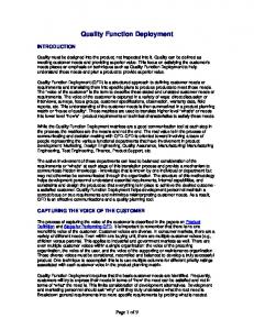
The QFDS process was developed as an alternative to the initial sizing assignment. Students were guided through the exploration and analysis of requirements. Process deliverables, shown in Figure 1, directed subsequent analytical steps which culminated in a final report.
The WPT mission is to be a firstmission at UIUC. Anticipating the environmental inertia involved in attempting any new activity, ground rules were defined to enhance the probability that the experiment would actually take place. These ground rules, with the process developed for the s/c design course, aided in designing -to-cost.
TOTAL SCIENCE Beaming Science Core Science Receive Microwave Power from the Ground Convert Microwave Power to Useful DC Power Maximize Time Within Uplink Power Beam Test Communications Interference With Microwave Beam Measure Rectenna Efficiency Degradation With Time
Supplemental Science Measure Beam Sidelobe Strengths and Distributions
Compare Short-Distance Beaming (Boom to S/C) With Earth-to-Ship Beaming
Atmospheric Science Effects on Ionosphere Test Power Density Necessary to Alter Ionosphere Perform In-Situ Tests of Ionospheric Interaction
Emphasize Cheaper
Beam Degradation Effects
Employ High Level of Ground Autonomy
Measure Atmospheric Absorption Under Different Weather Conditions
Examine Atmospheric Scattering of Beamed Microwaves
The Process
Cost Strategies
Examine Effects of Microwave Transmission Through a Turbulent Atmosphere
Test Solar Cell Degradation and Annealing to Restore Solar Cells
Minimize Launch Cost
Requirement Grouping
The Augmented QFDS process involves five steps.
Brainstorming
QFDS Engineering Requirements
(WHATs)
(HOWs)
Customer Requirements LOW-COST TOTAL MISSION 1 Minimize Total Mission Cost
Cost Strategies 2 Emphasize Cheaper 3 Employ a High Level of Ground Autonomy 4 Minimize Launch Cost
Low S/C Cost 5 Maintain S/C Development Costs Under $2 Million
4
1 111030000
11111
4 1 4
9 919130000 0 001000000 1 000101110
13999 00000 10000
3
1 110090000
91311
3
0 909333333 0 909333333
39999 39939
2 3
9 301131111 9 100333333
33911 33311
0 911331311 0 033100900 0 100100900 0 000000000
39999 93399 93311 00011
0 000000000 0 010000000 0 000000000
01103 00030 00010
S/C Components 6 Use Existing Components and Software Whenever Possible 7 Operating Prototype of All Tech. Must Exist Early 3 Schedule 8 Emphasize Faster 9 Design-to-Launch Less Than Five Years
1. Ground Rule Development Requirements Analysis 2. Affinity Diagramming: Functional Grouping of Requirements 3. Fishbone Diagramming: Structured brainstorming associated with grouped
(On-Board Design Overlap) Uncomplicated Configuration 10 Employ Simplicity of Design 11 Emphasize Smaller 12 Microsatellite 13 High Density Packaging
3.5 3 2 1
S/C Autonomy 14 Employ a High Level of 1 On-Board Autonomy 15 Test Signal-Locking of Link 16 No Orbital Debris
3 5
Rating of Ideas
Figure 1: Process Deliverables Student response to the process was not initially enthusiastic. It was
3
requirements to develop engineering solutions 4. Simplified House of Quality I: Ranking the requirements according to their importance to mission success and satisfaction of mission ground rules. 5. Simplified House of Quality II: Rating the ideas generated in step 3 by their importance to mission success.
the need to retain technical superiority set the target. Political pressure to make the task popular made it a manned mission. A decade was forecast as the time frame within which these goals would be important. Another example of ground rules devised to help achieve the strategic goals of a mission is found in Project Copernicus, a study of the Earth Observing System (EOS) satellites1, in the 1991 MIT space system engineering course.
Ground rule development was not included in the classroom application, but it played an essential role in designing -to-cost. Subsequent text will describe the implementation of these steps with examples and comments.
• • •
The strategic goal was set by the scientific community. The ground rules reflect an environment of public and scientific eagerness to understand global warming, and the uncertainty of future funding levels. They affected the design in the following ways. Unprecedented scientific results permitted innovative designs and payload integration techniques. Flexibility mandated consideration of both budgetary changes and payload changes as mission science goals evolved.
Mission Ground Rules and the Environment Design ground rules are set up to help in making decisions that are related to the strategic purpose of the mission and are affected by the environment in which it is being realized. Perhaps the classic example of space mission ground rules are those of the Apollo program. President Kennedy announced, “...we choose to go to the moon in this decade.” Program decisions revolved around three touchstones. • • •
Design to ensure continuity Design to achieve unprecedented scientific results Design for maximum flexibility.
While the flexibility issue does touch on cost, none of the Copernicus ground rules aid in design-to-cost, nor did the Apollo ground rules. Both were programs of the traditional form -design, cost from the bottom up, determine the impact, iterate if necessary
Man Moon Decade
These three words summed up the strategic purpose and the environment. Competition with the Soviet Union and
4
to meet budget constraints if there are any.
then you have a better program by definition.
The strategic goal of the WPT project was to develop a satellite construction capability at UIUC. The defining environment was the need to execute the mission within the current culture of the university and with the university assets available. The ground rules developed are listed below.
It may be that the order is dictated by the culture in which the program is being realized. In the case of the WPT example, financial constraint is the primary mission driver. University student stipends and fellowships will not have the same impact on a program that “real world” wages will. On many programs, students work for nothing because they are interested in the project or they value the experience. Hardware, facilities, and transportation will be the chief cost drivers and the magnitude of available funding is such that every possible price reduction is mandated in order to make a project feasible. For this reason, cheaper was placed first in the triplet.
• • •
Maintain simplicity in the design. Emphasize a 1) cheaper, 2) faster, 3) better solution. An operating prototype of each of the technologies employed must be demonstrated (or available in the industry) early in the program in order to be included in the design.
The new-start nature of the mission dictated maintaining design simplicity. The resources of a construction infrastructure are not in place, so simplicity throughout the project’s cycle life -- manufacturing, integration, test, and operation – is favorable to mission success.
Nevertheless, schedules slips will drive up costs. There is a stricture involved in meeting a launch deadline. A two-year lead time is common, with intermediate milestones such as reviews and testing, occurring during that period. For students working only half or one quarter work weeks, this is not an abundant amount of time. Additionally, it is important to complete development phases within the careers of students involved in the project. Students must attain closure of the activities to which they are assigned in order for them to frame the experience and give it meaning. Schedule was placed second.
Faster, cheaper, better have become industry by-words in the 1990s. Colonel Pedro Rustan credits this paradigm with the success of the BMDO Clementine mission2. He emphasizes the importance of the order of the three words as being crucial to their implementation – faster, cheaper, then better. In his view faster is first because schedule slips drive up costs. Cost is what you’re trying to keep down. If you can accomplish the first two items,
If the costs can be controlled and the schedule met, then there is a good chance that the mission will be completed. The question, “Is it a better
5
program because it was cheaper and faster?” is best answered, “There IS a program because it was inexpensive and efficiently completed. This is a ground rule that introduces the idea of design-tocost into the project mindset.
a) Minimization of early development costs b) Minimization of total development costs c) Minimization of the average cost per satellite launch and flight
The final ground rule demands that, early in the program, there must be a working prototype of a technology in order for it to be considered for the mission. The mission is a feasibility demonstration rather than a technology development or technology qualification mission. Contrast this with the Copernicus ground rule which allowed innovations in the program to achieve unprecedented scientific results.
Everything must be minimized, but no target is given. Cost minimization is relative to the level of performance achieved. A null system best meets these requirements. Performance levels are stated in terms of operational life, and on-orbit capabilities. The on-orbit capabilities required are stated below. a) The FFDAT system shall be capable of detecting, locating and differentiating from other heat sources, a potential forest fire. b) The FFDAT system shall be capable of an alert signal to appropriate ground station personnel. c) The satellite shall be capable of capturing and transmitting images of the identified “hot spot.”
Formulation of Requirements The subheadings under Requirements Analysis, step two of the AQFDS process, refer to steps which are to be taken in order to meet customer needs. It is, however, the duty of the entity devising the mission requirements to state them in unambiguous terms. If this is not done, then it is the job of the designers to go back to that entity and obtain clarification.
The specific level of performance is ambiguous. There is no mention of how well the system has to do each of these tasks. This leaves it to the designers to set a performance level and then minimize the cost of that system and its operational capabilities. As we have seen, depending upon the accuracy of designers’ perceptions of the current environment, and hence how well the ground rules reflect that environment, the system could comprise technology which delivers unprecedented results as in Copernicus or use existing prototypes
In the 1994/1995 AIAA/Loral Undergraduate Team Space Design Competition 3, over half of the bulleted requirements and constraints listed are directly or indirectly related to cost. Note the wording used in the request for proposal (RFP) for a microsatellite to perform a Forest Fire Detection and Tracking (FFDAT) mission.
6
and available technology. impacts are very different.
•
The cost
• Mission requirements for the WPT project were not handed down by an external entity. Their formulation was part of the design exercise. Scientific and performance requirements were derived from WPT literature and from surveying investigators in the field of radio wave transmissions through the atmosphere. They begin with a statement which is followed by a loosely-categorized listing of specific goals.
• • • • •
Secondary Goals
Requirements Statement
•
Design a microsatellite to successfully receive microwave power from the ground and convert it to useful DC power. Measure the microwave-toDC conversion efficiencies as functions of power density and time. Measure atmospheric absorption under different weather conditions. Examine atmospheric scattering. Measure rectenna efficiency degradation with time. Measure the radar beam sidelobe strengths and distributions.
•
•
•
•
Perform in situ tests of ionospheric interactions with microwave beam. Test the power density levels necessary to initiate ionospheric non-linearities.
Tertiary Goals • •
Test solar cell degradation and annealing to restore solar cells. Compare short-distance beaming (accomplished solely on board the s/c) with Earth-to-space beaming.
The statement gives the core requirements – receiving and converting microwave power aboard the microsatellite. As in the AIAA/Loral requirement list, the ambiguous word “minimize” is associated with many of the performance and cost-related items. However, there is an explicit cost target given for the s/c development. While the levels of performance, e.g., how much power must be transferred, are not well described, the cost target sets an implicit performance target. We can not consider
Primary Goals •
Minimize on-board attitude control systems. Use a passive satellite propulsion system (unfueled). Orbital debris as a result of this mission is precluded. The period from design to launch must be less than five years. Minimize total mission costs. Maintain s/c development costs under $2 million. Minimize launch costs.
Design an experiment to test space communications interference. Test phase locking of link from ground station as craft comes over the horizon. Employ a high level of autonomy in both ground control elements and on board the s/c. Maximize the time the satellite is within the uplink power beam.
7
a large, complex platform or the development of an enhanced power conversion system for the payload since these would likely break the budget.
Table 1: Requirement Definitions Minimize Total Mission Cost
Requirement Analysis Functional Grouping of Requirements First, the ground rules and requirements were divided into twentynine concise statements and enumerated. A definition was developed by designers for each requirement. These were written down along with any clarifying comments. A few selected example definitions are given in Table 1.
Minimize Launch Costs
8
Second only to the core requirements of receiving and converting beamed power, this is considered to be the overriding mission requirement. Design, development, manufacture, test, evaluation, integration, launch, operation, and end-of-life costs must be the lowest possible. There is no point in flying the mission if the power can not be collected, converted and measured, but the mission must be a low-cost demonstration. The lowest-cost launch and integration system that fulfills the beaming requirements shall be selected.
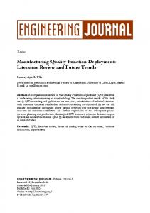
Once the meaning of each of the requirements was made clear, they were divided functionally into groups and charted as affinity diagrams. Functional grouping helps to generate engineering solutions and strategies which can satisfy a number of requirements simultaneously.
The WPT affinity diagrams, presented in Figure 2 represent the work of a single designer. Greatest advantage is attained when Affinity Diagramming is performed by a team.
TOTAL SCIENCE
LOW-COST TOTAL MISSION Beaming Science Core Science Minimize Total Mission Cost
Cost Strategies
(On-Board Design) Uncomplicated Configuration
Emphasize Cheaper
Employ Simplicity of Design
Employ a High Level of Ground Autonomy
Emphasize Smaller
Minimize Launch Costs
Receive Microwave Power from the Ground Convert Microwave Power to Useful DC Power Measure Amount Power Received Test Communications Interference With Microwave Beam
Microsatellite High Density Packaging
Measure Time Dependence of Rectenna Efficiency
Low S/C Cost Maintain S/C Development Costs Under $2 Million
Measure Range Dependence of Rectenna Efficiency
S/C Components Use Existing Components And Software Whenever Possible An Operating Prototype of All Technologies Must Exist Early in the Development Process to Be Included
Atmospheric Science Effects on Ionosphere Test Power Density Necessary to Alter The Ionosphere Perform Tests of Ionospheric Interaction Effects
Effects of Troposphere Measure Atmospheric Absorption Under Different Weather Conditions
Examine Effects of Tropospheric Microwave Transmission
S/C Autonomy Supplemental Science Employ a High Level of On-Board Autonomy
Measure Beam Sidelobe Strengths and Distributions
Test Signal-Locking of Link
Compare ShortDistance Beaming With Earth-to-Ship Beaming
No Orbital Debris
Schedule
Test Solar Cell Degradation and Annealing to Restore Solar Cells
Emphasize Faster Design-to-Launch Period Less Than 5 Years
Figure 2: WPT Affinity Diagrams The requirements are written on index cards, one per card, and laid out, face up, on a table. Without comment from the rest of the team, the first team member arranges the cards into groups. When he or she is satisfied, it is the second person’s turn to adjust the groupings. There may be nothing left of
the original groupings by the time the second person finishes. The grouping process continues until the team is satisfied with the arrangement. Though the exercise is designed to be completed in silence, there were cases where students working on the FFDAT project were more effective when they were
9
allowed to discuss the groupings as they were being formed.
the need to obtain meaningful scientific results. Strategic cost requirements -economical subsystem designs, cheaper components, low-cost launch services, and a highly-autonomous ground segment -- were tactics for fulfilling that overarching goal.
After the grouping is completed, a title is given to each collection of requirements. This completes the first grouping level. The group title, along with the requirements under that heading, is written on new index cards, one group per card. The grouping process is repeated at the second level, arranging the groups into super-groups. The grouping process moves to higher and higher levels until the grouped requirements can be categorized no further.
The s/c cost cap provided a target which helped to keep design choices in perspective. It guided component selection and scheduling decisions. Spacecraft configuration requirements straddled two higher-level groupings. They were related to the cost cap and to the issue of on-board autonomy. This dual role was reflected by allowing two groups to overlap. Engineering solutions were generated for both groupings.
In Figure 2, the first level groupings were • • • • • • • • • • • •
Minimize Total Mission Cost Cost Strategies Maintain S/C Development Cost Under $2 Million S/C Components Schedule Uncomplicated Configuration S/C Autonomy No Orbital Debris Core Science Supplemental Science Effects on Ionosphere Effects on Troposphere
It is essential to write down the word or thought that creates the link between the various requirements and groups. If the link is vague, writing it down will reveal the weakness and could result in a better arrangement. When finished, every member of the design team should have a clear understanding of why this particular organization resulted. Even in the absence of teammember inputs, an individual designer can benefit from using the process. It is useful to complete the process once, put the work aside for a time, and then repeat the diagramming after a period of at least a few days. In the WPT study, the cooling-off period lead to significant alterations in the groups.
The completed hierarchy had three levels. At the second level, requirements related to cost were those first separated out. The overlying dictate to minimize total mission cost formed a category of its own. It was viewed as the driver of the design, though it was balanced with
Structured Brainstorming
10
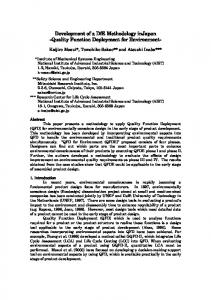
heading in the affinity diagram are placed along the ribs which extend from the spine. By placing all grouped requirements on one diagram, each requirement can be addressed separately while the common theme of the group is graphically retained. The first synergisms of the mission configuration begin to form during the fishboning process. A deeper understanding of the mission challenges results.
Setup Fishbone diagram construction was used as a structured method of generating and recording designer responses to the input requirements. The affinity diagram groupings map directly to the fish skeletons. Figure 3 illustrates the transformation. An affinity group title is placed in the box representing the head of the fish; requirements below that
For the WPT mission diagram of Figure 2, fishboning was done for the following groups. • • • • •
Beaming Science Atmospheric Science Cost Strategies Low Spacecraft Costs On-Board Design
Only the Minimize Total Mission Cost requirement was not included. This, again, was considered so overarching, that it pervaded each of the diagrams.
11
Maintain S/C Development Cost Under $2 Million
S/C Components
Use Existing Components Whenever Possible An Operating Prototype of All Technologies Must Exist Early in the Development Process to be Included
Low S/C Cost
Emphasize Smaller
Emphasize Faster
Simplicity of Design Design-to-Launch Period Less Than 5 Years
Microsatellite Use Passive Satellite Propulsion System High Density Packaging Minimize On-board Control Systems
Uncomplicated Design
Configuration
Schedule
Figure 3: Second Level Fishbone Diagram Structure Skeletons are constructed at a level research topics in which he or she has convenient for the generation of weaknesses prior to beginning. That was engineering solutions. A second-level the case for the WPT design. grouping is illustrated in Figure 3. The level selected should help designers to Before doing the research, an initial understand requirement connectivity cut at fishboning took place. A few days without becoming overwhelmed by were allowed to pass, then additional having to deal with too many ideas were generated. Brainstorming at requirements at once. It is also desirable this stage pointed to specific areas that to generate figures which are legible. needed investigation. An informationgathering period followed. The AQFDS Prior to filling in the skeletons, it is process was then repeated starting with important to determine if the required Affinity Diagramming. This approach expertise is available to generate useful lead to a deeper perspective and fresh ideas. Are all the pertinent design ideas, and the targeted information specialties covered? For group design, gathering was believed to have review at this stage helps in staffing the compressed the research period. team. With a group of students who Action may have scant experience in the fields in A single class period was set aside which they will be designing, the lack of to introduce the FFDAT students to the expertise becomes evident during fishboning process. Skeletons were brainstorming. In this case, fishboning recorded on a blackboard, and results will help to direct efforts into areas were copied into a design notebook by which need clarification and exploration one of the team members. An in the early stages of the project. An improvement in the process occurred individual going through the fishbone when blank transparencies were diagramming process is forced to projected on an overhead and ideas were
12
recorded. The transparencies did not have to be hand copied. They could be photocopied and distributed to all team members.
Results The resulting Low Spacecraft Cost, WPT fishbone diagram is shown in Figure 4. For brainstorming, recording the ideas on the fishbones is convenient. For presenting them on paper, it is not. The relationships are retained and are easier to brief if they are presented in outline form as in the figure.
Each requirement on the fishbone becomes the subject of a brainstorming exercise. Engineering responses to the challenges posed by the requirements are recorded as small bones on the charts. Despite the functional groupings, it is not unusual to generate an idea that seems to belong on more than one bone or on multiple fish. There are benefits derived from recording an idea on more than one diagram, because its inclusion can start a train of thought which differed from that generated for another of the functional groupings.
Note that component choice, configuration and schedule can all be addressed on one figure. The synergy between the requirement to meet the $2million cost cap and the components selected is evident. Ideas generated for both point to minimal technology development and use of COTS products. It is usually not the case that mission designers compile the requirements for a program and then carry out the design, but requirements do evolve during the concept exploration phase of a design. Sometimes analytical results initiate requirement restatement. Sometimes the need rephrasing for clarity.
Rules for brainstorming were put in place. 1) No comment can be made on another person’s ideas. 2) No single person’s ideas are more important than any other’s. 3) Try to generate as many ideas as possible in the time alotted. Quantity, not quality, is sought.
An unexpected benefit of the fishboning process was the discovery that some requirements had not been properly specified and that some were not requirements at all. Two first-round requirements generated from the ground rules were to “identify and quantify risks associated with unproven technology.” and “make conservative use of developing technology.” No ideas resulted when these were brainstormed. They were examined and restated into the addressable requirements to “use existing components whenever possible”
These may seem obvious, but they are often ignored when brainstorming. It has been the author’s experience to hear a supervisor say, “I don’t know about the rest of you, but some of these ideas are making me gag,” or “That’s about the stupidest remark I’ve ever heard.” Effectively, very effectively, the brainstorming is over, and designers will be insecure about the value of the ideas that were generated.
13
and “an operating prototype of all technologies must exist early in the development to be included.” So the brainstorming iteratively refined the program all the way back to the mission ground rules.
became engineering solutions. “Simplicity of Design” was added to the “Configuration” group, and the new arrangement was titled “Uncomplicated Configuration.” The amended grouping with the associated ideas is shown in Figure 4.
An early grouping of requirements was shown in Figure 3. One rib, titled “Uncomplicated Design,” went through a complete reorganization during the brainstorming. Use of passive satellite propulsion had potential conflicts with no orbital debris. “Minimize on-board control systems” was at odds with the requirement to phase-lock the link. Passive satellite propulsion and minimal control systems were seen as design options rather than requirements, and
Following the brainstorming, agreement has to be reached among the designers as to what precisely was meant by the stated ideas. Definitions were arrived at for each. Whether being done by an individual or a group, defining the engineering solutions provides design traceability. It helps in understanding why a solution may have been discarded early in the design, and why it may subsequently be worth reconsideration.
14
Low Spacecraft Cost Maintain S/C Development Costs Under $2 Million -Student design & manufacture -Minimal technology development -Use common, handy hardware where practical
S/C Components -Use existing components whenever possible -Minimal technology development -Rectenna from Univ of TX at Austin -Other existing rectenna prototypes -An operating prototype of all technologies must exist early in the development to be included -Rectennas -No inflatable structures -Existing science technologies -COTS for hardware -COTS for software
Uncomplicated Configuration
Schedule
-Employ simplicity of design -Store and forward data -Low number of deployables -No solar arrays -No battery charging -Common voltages -Easy to assemble -Easy to test -Easy to troubleshoot -Modular -Flexible to lifecycle OSIF’s -Use passive propulsion -No thrusters -No fuel -Passive desaturation -Minimize on-board control systems -Momentum wheel -Gravity gradient -Spin -No solar array controllers -Non-directional antenna -Non-directional rectenna -GPS receiver -Emphasize smaller -Dense packaging -Minimal data storage -Low power components -Modest expectations -Flight qualify miniature prototypes -Microsatellite - ~30 cm cube -25-100 kg -High density packaging -Low power usage -High efficiency electronics -High temperature electronics
Notes: COTS = Commercial, Off-The-Shelf GPS = Global Positioning System OSIF = Oh Shoot, I Forgot...
-Emphasize faster -Design for transport -Select uncomplicated manufacturing methods -Begin construction when students have most time -Summer -Design-to-launch period less than 5 years -Design 1-5 years -Construction, test and integration 3-3.5 years -Select launcher within that time frame
Figure 4: Low Spacecraft Cost Skeleton Construction and Use of a Simplified House of Quality
It also served to further requirement traceability.
Setup
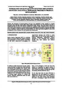
The WPT house of quality consisted of a 179-by-29 relationship matrix. The left column contains the customer’s requirements. These are WHAT the customer would like the system to do. Across the top are the engineering solutions. These represent HOW engineers propose to deliver what the customer needs. Ideas duplicated in the fishbone diagrams were not
Figure 5 gives a sample from the Simplified House of Quality generated for the WPT mission. While it does not include many of the features of a fullblown house of quality, it proved useful in this form to aid in selecting the most promising candidate ideas to best satisfy the cost and performance requirements.
15
ensure
Test Schedule Carefully Power Use Not S/C Batteries Switch InGround Travel Use University Off S/C Only for Use Station Systems Bus For Existing, Student-Staffed FREJA-C When OSC Commercial OSC Pegastar TRW Microlab Ball Eagle QuickStar Surrey Passive Satellite Passive Thermal “Solar Attitude Permanent Array” Control Control SunMagnets Sensors
Engineering Requirements
(HOWs) (HOWs)
(WHATs) (WHATs) Customer Requirements LOW-COST TOTAL MISSION 1 Minimize Total Mission Cost
Cost Strategies 2 Emphasize Cheaper
Customer Requirements
4
1 1 1 1 0 3 0 0 0 0 1 1 1 1 1
4
9 9 1 9 1 3 0 0 0 0 1 3 9 9 9 0 0 0 1 0 0 0 0 0 0 0 0 0 0 0 1 0 0 0 1 0 1 1 1 0 1 0 0 0 0
3
1 1 1 0 0 9 0 0 0 0 9 1 3 1 1
S/C Components 6 Use Existing Components and Software Whenever Possible 3 7 Operating Prototype of All 3 Tech. Must Exist Early
0 9 0 9 3 3 3 3 3 3 3 9 9 9 9 0 9 0 9 3 3 3 3 3 3 3 9 9 3 9
3 Employ a High Level of Ground Autonomy 4 Minimize Launch Cost
Low S/C Cost 5 Maintain S/C Development Costs Under $2 Million
Schedule 8 Emphasize Faster 9 Design-to-Launch Less Than Five Years
TOTAL SCIENCE Beaming Science
4 1
2 3
Core Science 17 Receive Microwave Power from the Ground 18 Convert Microwave Power to Useful DC Power 19 Measure Amount of Power Received 20 Test Communications Interference w/ Beam 21 Measure Time Dependence of Rectenna Efficiency 22 Measure Range Dependence of Rectenna Efficiency Supplemental Science 23 Measure Beam Sidelobe Strengths/Distributions 24 Compare Short Distance w/ Earth-to-Ship Beaming 25 Test Solar Cell Degradation & Annealing to Restore Cells
9 3 0 1 1 3 1 1 1 1 3 3 9 1 1 9 1 0 0 3 3 3 3 3 3 3 3 3 1 1
3.5
11 Emphasize Smaller
3
12 Microsatellite
2
13 High Density Packaging
1
S/C Autonomy 14 Employ a High Level of On-Board Autonomy 15 Test Signal-Locking of Link 16 No Orbital Debris
5 5 3 4 4
0 0 0 0 0 0
0 0 0 0 0 0
0 0 0 0 0 1
0 0 0 1 0 0
1 0 0 1 0 0
1 0 0 1 0 0
1 0 0 1 0 0
3 0 0 3 0 0
1 0 0 1 0 0
1 0 0 1 0 0
1 0 0 1 0 0
0 0 0 0 0 0
0 0 0 0 0 0
1 0 0 1 0 0
1 0 0 1 0 0
1
0 0 0 0 0 0 0 0 0 0 0 0 0 1 1 0 0 0 0 0 0 0 3 0 0 3 0 0 0 0 0 0 0 1 0 0 0 0 0 0 0 0 0 1 0
Effects on Ionosphere 26 Test Power Density Necessary to Alter Ionosphere 3 27 Perform Tests of Ionospheric Interaction Effects 3
0 0 0 0 0 0 0 0 0 0 0 0 0 1 1 0 0 0 0 0 0 0 1 0 0 0 1 0 1 1
Effects of Troposphere 28 Measure Absorption Under Different Conditions 29 Examine Effects of Tropo., Microwave Transmission
1
0 0 0 0 0 0 0 0 0 0 0 0 0 1 1 0 0 0 0 0 0 0 0 0 0 0 0 0 1 1
2.98
92
2 1
Atmospheric Science
(On-Board Design Overlap) Uncomplicated Configuration 10 Employ Simplicity of Design
5
1 3 5
0 0 0 0
9 0 1 0
1 3 0 0
1 3 0 0
3 1 1 0
3 0 0 0
1 0 0 0
3 9 9 0
1 0 0 0
1 0 0 0
3 9 9 0
9 3 3 0
9 3 3 0
9 9 1 1
9 9 1 1
0 0 0 0 0 0 0 0 0 0 0 1 1 0 3 0 0 1 0 0 0 0 0 0 0 0 0 0 3 0 0 0 0 0 0 0 0 0 0 0 0 0 0 1 0
Importance Rating
3
139.5 30.5 113.5 60.5 102.5 44.5 118.5 44.5 40.5 138.5 138.5 177.5 180.5 186.5
Figure 5: Example from Simplified House of Quality duplicated in the house. Some of the engineering solutions in Figure 4, such as “Minimize on-board control systems,” addressed a requirement at the system level. Subsystem level ideas were also generated. Both the levels were included as column headings.
drivers. Generally, every requirement is not critical to mission success. The figure arrived at in the WPT study was 2.98, just below the center of the acceptable range. Table 2: Customer Requirement Ranking Criteria 1 Not important to mission success 2 Somewhat important to mission success 3 Fairly important to mission success 4 Very important to mission success 5 Critical to mission success -> Design driver
As a first step, the requirements are ranked, from five to one, by their importance to the mission. Rankings are recorded in the second column. Table 2 gives the ranking criteria used. The average of these rankings should be somewhere between 2.5 and 3.5. If the average is below 2.5, designers are saying that most requirements are not very important. If the average is above 3.5, it is likely that the team has not been careful enough in identifying designer
Ideally, it is in the designers’ best interests to elicit these rankings from the customer prior to proceeding. There are
16
instances where they must make the call on which requirements are the most important. At times, particularly in an educational setting, it is not possible to interview the customer. In industry, this function is sometimes deemed to belong to marketing and is considered out of the province of engineers. Other times, the customer is not easily defined. The purchaser and the user have very different slants on what is important.
relationship matrix. This permits direct traceability of the design path. Due to the additional time this task would have involved, it was not performed either by the students using this process or by the author for the WPT design. Instead, where the decisions were not obvious, it was recommended that notes be made in the margins or blank areas of the matrix to remind participants of the reasoning that lay behind that decision.
After the rankings have been agreed upon, the relationship matrix, the rowcolumn intersections, is completed. Table 3 gives the criteria used to evaluate the importance of an engineering solution in fulfilling a customer requirement. Each HOW was considered in turn.
After filling in the relationship matrix, the rankings were multiplied by the relationship value and totaled down each column of the matrix. The figure at the bottom of the column was that HOW’s importance rating. The weights of both the cost ground rules and the cost requirements have been used to evaluate the importance of performancerelated design solutions. These evaluations must be confirmed with trade-off studies, but the trade space has been reduced significantly. Only the highest ranked ideas are subject to trade.
Completing the matrix also helped to refine the requirements. In some cases, an engineering solution was fulfilled by a design requirement rather than the other way around. In these cases, the HOW and WHAT had to be studied to determine if their places should be reversed.
Use of the Importance Ratings
Table 3: Relationship Matrix Values Numeral 9
Relationship Strong
3
Medium
1
Weak
0
None
HOWs were sorted by their importance ratings. It was found that there were two bunches of highly-rated engineering solutions at the top of the list followed by a linear decline which made grouping difficult. The two bunches contained the ideas which were carried into the analytical phase of the design.
Thought Satisfies the requirement by itself. Satisfies the requirement in conjunction with one or two other HOWs. Satisfies the requirement in conjunction with many other HOWs. Does not satisfy the requirement.
For mission science and the spacecraft configuration, the sorted HOWs, weighted in importance by their cost and performance attributes, were
A thorough analysis would include documenting each decision made in completing the rankings and the
17
referred to explicitly in selecting options to analyze. For example, the applicability of ionospheric science instruments was limited by cost restrictions which pointed to a small, secondary payload, as well as the beamed power levels available and radio frequencies selected. Another example was an effort to make ground-based radio wave interference measurements which was considered. The measurements would not be difficult to make, but the transportation costs associated with the science along with its relatively low importance to mission success eliminated it from the program.
previous studies results of similar projects by Keith Rogers4 and the University of Alaska at Fairbanks5 (UAF). Table 4: Cost Comparison With Previous Studies Study Rogers Univ. of AK
$ Million 8-10 24
Univ. of AK
7
Current Mission
Notes For Half Mission Half Mission Minus LV
1-2
The goal of the Rogers’ study was to investigate the possibilities for an inexpensive WPT demonstration using existing facilities. A specific cost target was not given. Developing technology was not ruled out for the spacecraft.
For the launch vehicle, radar station and ground station, the listings were used implicitly. For example, the performance of the ground-based radar station was considered from the standpoint of acceptable frequency, power level, aperture size and tracking capability. Because of the cost ground rules and requirements, radar stations qualifying on the basis of performance were then compared by cost. These costs had to be collected by the engineer from authoritative sources. It was determined to select a primary and backup architecture – one which is more acceptable purely on cost and performance, and one which might be preferred due to circumstantial or political reasons.
The UAF study was constrained in cost, experimental requirements, technology development, launcher capability, communications limits and the space environment. Again, no specific cost target was included. Ambitious experimental requirements to include both laser and microwave WPT in the mission lead to the selection of a dedicated, Pegasus launch rather than the secondary launch of the current study. For the current design-to-cost study, the philosophy was, “This is the money we have, what can we do?” Understanding the customer’s needs when ranking the performance and cost requirements relative to one another, helps to answer the question of whether what we are able to do is satisfactory.
WPT Results Table 4, illustrates the success of the process in designing to cost. The current mission’s cost is compared with
Lessons Learned Design-to-Cost
18
much as is possible, to define what adequate performance is and where to circumscribe the cost box boundaries.
The two aspects important to successfully designing to cost were identified from use of AQFDS. 1) The importance of the cost constraints to program success must be made clear to designers in unambiguous terms at the outset. 2) Engineers must understand the costs associated with their design solutions. Corporate policy can lay down ground rules and strategies which emphasize low-cost approaches. These policies and ground rules must be included in system analyses. More importantly, either the acceptable degree of system performance or the cost has to be explicitly specified in order to know at what level the system is to be “minimized.” Formerly, the costing function has been regarded as an effort subsequent to design completion. Astronautical engineers and scientists are historically unaware of the final costs of systems or components they have designed. Because performance was more highly stressed than cost, the subject often never arose. This was because a system providing the best performance, so long as the dollar value was not outrageous, was usually selected by the customer. Things are changing. For valueconscious customers, a system may outperform competitors, but if it is outside the cost box, or if adequate performance can be obtained at a savings, the system is increasingly less likely to be procured. It is up to the customer, as
19
Educational Settings and Requirements Generation A chief hurdle in teaching the design of aerospace systems is generating the mission requirements. An abbreviated version of AQFDS could be a tool for generating reasonable, wellstated requirements for the course. Because of its value in identifying badlystated requirements and items which are engineering solutions rather than requirements, it has potential as an instrument for government and industry requirement-generating bodies when editing RFPs. The process could also be applied to AIAA, IEEE and SAE design competitions to help bookkeep designs and project budgets. AQFDS can aid in identifying areas of weakness among the participants and contribute to the efficient allocation of assets. Program Impact In the classroom, the process was alotted three weeks from the delivery of the requirements through the submission of the completed houses of quality. The exercise was initiated in six classes which lasted three hours and was assigned concurrently as homework during that three-week period. Six to seven students comprised a group. For the WPT project, the entire process, including the definitions and the 179-by-29 matrix, was completed by a single person with a full-time-plus workload in three weeks not including requirement generation.
20
Conclusions
Engineering graduate seminar University of Illinois at UrbanaChampaign, April 4, 1995. 3 “1994/1995, AIAA/Loral Undergraduate Team Space Design Competition,” release 6/13/94. American Institute of Aeronautics and Astronautics, Washington, DC, 1994. 4 Rogers, Keith, "Design of a LowCost, Earth to Space Power Beaming Demonstration," Space Power, Vol 12, Nos 1 & 2, 1993, pages 7-22. 5 Hawkins, Joe, et al, "Wireless Space Power Experiment," in Proceedings of the 9th Summer Conference of NASA/USRA Advanced Design Program and Advanced Space Design Program, June 14-18, 1993.
A process has been tested and demonstrated in an educational setting as an aid in designing to cost. Process success was tied to explicit inclusion of cost requirements early in the analytical stages of design. Functional grouping of requirements leads to a strategy of efficient satisfaction when synergisms are identified early in the design process. Ranking vital requirements and relating these to ideas which best satisfy the technical and cost requirements can act as a guide throughout the process. Design-to-cost is an industry goal. Two paradigms were identified as being important to its achievement.
Steve Deal is a systems engineer for TRW. He received his MS from University of Illinois at UrbanaChampaign in 1996 while working as staff engineer at SAIC. He received his SB from MIT in 1991. He has been teaching assistant for the spacecraft section Aerospace Vehicle Design course for the past three years.
1) Requirements which are explicit either in performance or cost, and preferably both. 2) Designers and engineers need to be educated as to the qualitative cost impacts of their decisions. Cost data should be part of the designer’s toolkit. References
Dr. Victoria Coverstone-Carroll is an assistant professor of Aeronautical and Astronautical Engineering at the University of Illinois at UrbanaChampaign. Her research interests include optimal low-thrust spacecraft trajectories, spacecraft design, and control of underactuated robots. She is a member of the American Institute of Aeronautics and Astronautics and American Astronautical Society.
1 Project Copernicus, Design of an Earth Observing System, Massachusetts Institute of Technology Space Systems Engineering, Spring 1991, Cambridge, MA, May, 1991. 2 Ruston, Pedro L., “The Clementine Lunar Mission: Technical Aspects and Results,” Department of Aeronautical and Astronautical
21
22