BROWN: RF-MEMS SWITCHES FOR RECONFIGURABLE IC'S. 1869 adjustment of a separate RF device or component, such as a variable capacitor. In many ...
capacitive switch architecture is very similar to a variable MEMS capacitor, with two stable states and a capacitance variation of orders of magnitudes between.
MEMS). RF applications of micromachining technology have included micromechanical switches and filters as well as high Q inductors and variable capacitors ...
CRLH-MTM-MEMS cell, which using MEMS technology can be reconfigurable by moving elements (variable capacitors). In particular, for antenna applications, ...
IEEE MICROWAVE AND WIRELESS COMPONENTS LETTERS, VOL. 13, NO. ... demonstrated to be one of the most promising technologies in developing ...
Wave), BAW (Bulk Acoustic Wave) and MEMS (Micro. Electro Mechanical Systems) acoustic micro-resonators have been developed to fabricate efficient filters ...
Apr 30, 2014 - Review Article. MEMS-Reconfigurable Metamaterials and Antenna Applications ... beam steering without the need for a beam-forming network.
antenna loaded with MEMS capacitors is shown in Fig. .... Therefore, the CPW stub provides a variable load to the radiating edge it is connected, resulting in ...
WITH MILLI-DEGREE ACCURACY. C. M. Jha, G. Bahl ... 0.008°C which is comparable to that of the best CMOS temperature sensors available today. Keywords: ...
Nov 14, 2016 - the Central Universities (Grant No. 3102015ZY058 and 3102015ZY079). Vol. 24, No. 24 | 28 Nov 2016 | OPTICS EXPRESS 27103.
Nov 14, 2016 - Furthermore, frequency tuning range of SRR increases with the droplet height, ..... At the first stage without bias field, nematic LC molecules are randomly ... carried out via electrostatic solver of CST EM studio, as shown in Fig.
to experimentally explore classic parametric resonators such as described by the Meissner equation. We present experimental results showing parametric ...
May 20, 2014 - Nevsky, and Stephan Schillerâ. Institut für Experimentalphysik, Heinrich-Heine-Universität Düsseldorf, Düsseldorf, Germany. âCorresponding ...
a corresponding need for automated design and optimization methodologies that ... CA 94035 USA (e-mail: bkraus, [email protected]). while at the ...
Weiguan Zhang and Joshua E.-Y. Lee / Procedia Engineering 47 ( 2012 ) 949 â 952 resonator with a simple crossbar heater capable of achieving a tuning effect ...
[5] S. Beeby, MEMS Mechanical Sensors, Artech House Publishers, Nor- wood, 2004. [6] C. T.-C. Nguyen, et. al., âAn integrated CMOS micromechanical res-.
Mar 9, 2018 - (MR-WPT) system with a reconfigurable planar receiver (Rx) to optimize transfer efficiency (TE) for laptop application has been investigated.
unturned frequency of 39.2 kHz with 50mW power. By utilizing comb drives instead of parallel plate transducers, frequency tuning is controlled solely using joule ...
Apr 30, 2014 - This is an open access article distributed under the Creative Commons ... This paper reviews some of our contributions to reconfigurable ...
lyzer and Cascade Microtech 6â RF probe station with. ACP GSG probes. A. RF MEMS Reconfigurable Capacitor. A test capacitor was included on the chip for ...
Aug 2, 2013 - ... the past in the present; the infinite in the finite; these are to me the springs of delight and beauty. 'In Defence of Dagon' [1921]. H.P. Lovecraft.
As described above, the backplane provides a set of passive point-to-point ... Figure 2 shows a schematic diagram of the optical switch. ... the fiber in place in the initial (rest) position. For the .... pusher would release the driver allowing it t
May 23, 2018 - work Analyze (E5071C) and the setup shown in figure 2. The two flexure beams are used as logic inputs and are electrother- mally actuated to ...
Journal of Micromechanics and Microengineering
Related content
PAPER
A single MEMS resonator for reconfigurable multifunctional logic gates To cite this article: Sherif A Tella et al 2018 J. Micromech. Microeng. 28 095002
View the article online for updates and enhancements.
- A single nano cantilever as a reprogrammable universal logic gate K N Chappanda, S Ilyas, S N R Kazmi et al. - Novel threshold pressure sensors based on nonlinear dynamics of MEMS resonators Mohammad H Hasan, Fadi M Alsaleem and Hassen M Ouakad - Experimental and analytical study of highly tunable electrostatically actuated resonant beams Amal Z Hajjaj, Abdallah Ramini and Mohammad I Younis
This content was downloaded from IP address 109.171.137.211 on 31/05/2018 at 13:15
Journal of Micromechanics and Microengineering J. Micromech. Microeng. 28 (2018) 095002 (9pp)
https://doi.org/10.1088/1361-6439/aac13d
A single MEMS resonator for reconfigurable multifunctional logic gates Sherif A Tella, Nouha Alcheikh
and Mohammad I Younis
Physical Sciences and Engineering Division, King Abdullah University of Science and Technology, Thuwal 23955-6900, Saudi Arabia E-mail: [email protected] Received 18 January 2018, revised 7 April 2018 Accepted for publication 30 April 2018 Published 23 May 2018 Abstract
Despite recent efforts toward true electromechanical resonator-based computing, achieving complex logic functions through cascading micro resonators has been deterred by challenges involved in their interconnections and the large required array of resonators. In this work we present a single micro electromechanical resonator with two outputs that enables the realization of multifunctional logic gates as well as other complex logic operations. As examples, we demonstrate the realization of the fundamental 2-bit logic gates of OR, XOR, AND, NOR, and a half adder. The device is based on a compound resonator consisting of a clamped-guided electrostatically actuated arch beam that is attached to another resonant beam from the side, which serves as an additional actuation electrode for the arch. The structure is also provided with an additional electrothermal tuning capability. The logic operations are based on the linear frequency modulations of the arch resonator and side microbeam. The device is compatible with CMOS fabrication process and works at room temperature. Keywords: MEMS resonators, frequency tuning, 2-bit logic operations, half adder operation (Some figures may appear in colour only in the online journal)
1. Introduction
27]. Halg [28] demonstrated an integrated nonvolatile memory based on the bi-stable states of a micromechanical bridge. Yao et al [20] demonstrated both logic and memory unit from a single MEMS resonator integrated with a closed loop control to fix the output signal at a single frequency. There is an increasing interest in alternative computing architectures that can overcome the limitations of complementary-metal-oxide-semiconductor (CMOS) transistors-based computing, such as their inability to operate at high temper atures and their high off-state power consumption. Hence, there are demands for an alternative approach that will provide run time re-configurability to improve their functionality and energy efficiency. These demands have revitalized the objective of seeking for a scalable mechanical computation that can be traced back to the work of Charles Babbage in 1822 on calculating engines [29]. In addition, subsequent improvements in micro-/nano- fabrication and measurement techniques have revived research interest in mechanical computation and stimulate the use of MEMS/NEMS resonators for different logic and memory applications. Dynamic-based resonant
The past two decades have seen increasing interest in exploring micro/nano-electromechanical systems (MEMS/NEMS) for various applications, such as filters [1–5], switches [6–9], memory devices [10–12], and logic gates [13–18]. MEMS/ NEMS devices can be based on their static behavior, such as switches, or on their dynamic behavior, such as resonators and resonant sensors [19]. Due to their simplicity and high efficiency, MEMS switches have been excellent candidates to perform multifunctional switching operations, and more recently were proposed for logic and memory applications [12, 20, 21]. However, they suffer major drawbacks due to the contact and stiction problems. Thus, non-contact dynamicbased logic devices have received increasing attention the past few years [14, 18, 22, 23]. MEMS resonators are commonly operated in the linear regime. However, due to the geometric and electrostatic force nonlinearities, they can exhibit nonlinear behavior [24–26], which has been exploited recently for memory devices [20,
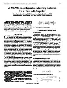
Figure 1. (a) A scanning electron microscope SEM image. (b) Schematic of the device (not-to-scale).
structures have been particularly under increasing interest for logic applications, where their on-resonance large response is considered a ‘High’ state and their off-resonance response is taken as ‘Low’ state. The fact these are non-contact devices make them especially attractive compared to MEMS and NEMS switch-based logic devices. The first attempt in this domain was presented by Masmanidis et al [17] who demonstrated a scalable dynamic mechanical logic gate (XOR) using an L-shaped nano-cantilever [30]. AND/NAND and OR/NOR logic gates were demonstrated using doubly clamped nanobeams operating in the nonlinear regime. A universal logic gate was demonstrated with multi-bit logic functions using a single parametrically excited resonator in [31]. Mita et al [32] demonstrated XNOR and XOR logic gates based on a single cantilever beam. Mahboob et al [33] reported 2-bit and multi-bit logic operations using a single electromechanical parametric resonator by encoding binary information as different oscillation frequencies. In [15], several basic 2-bit and 3-bit logic operations have been demonstrated using an electrothermally actuated arch resonator. Thus far, the realization of complex combinational logic gates has posed a great challenge. Toward this, Hafiz et al [34] reported an alternative approach to realize complex logic gates by cascading multiple electrothermally actuated resonators demonstrating a single bit binary comparator, a single bit 4-to-2 encoder, parallel XOR/XNOR and AND/NOT gates, and a 2:1 MUX [35]. However, cascading multiple MEMS resonators to perform complex logic operations introduces major challenges, such as the required interconnections between the resonators, the increase in the device complexity, and more fabrication restrictions. The development of fundamental and complex logic circuits with a single conceptual framework is key to realize a complete mechanical computing machine with run-time
Table 1. Dimensions of the beams composing the device.
Description Length (µm) Width (µm) Depth (µm) Initial curvature (µm) Gap between the microbeams and the electrodes (µm)
Beam 1 (arch beam) L1 h1 b1 bo1 D
600 2 25 1.7 10.6
Beam 2 (straight beam) L2 h2 b2
1000 50 25
g
2
programmability. Motivated by the challenges involved in cascading resonators to develop complex logic circuits, we demonstrate an alternative approach to realize both fundamental and complex logic circuits from a single MEMS microstructure. The microstructure is composed of a compliant shallow arch, which can be actuated electrostatically across its length and through its side near the anchor [36]. In addition, it can be actuated electrothermally. On the arch guided side is another resonant beam that can be actuated electrostatically and can modulate the stiffness of the arch. Therefore, this structure offers various possibilities to control stiffness, and hence, leads to various possible logic outputs. This enables programmability of the device to give different multifunctional logic operations depending on the combination of the inputs and outputs. With this concept, two different logic operations can be obtained simultaneously from the two outputs. In this paper, we demonstrate basic 2-bit logic operations, mainly OR/NOR, AND/XOR/NOR, and complex combinational logic half adder operation from the single MEMS structure. The proposed device will be shown as a promising platform for performing other complex logic circuits.
2
S A Tella et al
J. Micromech. Microeng. 28 (2018) 095002
Figure 2. Schematic of the experimental setup. The beams are biased with a DC load of 40 V superimposed with an AC signal of 20 mV (RMS), operating at room temperature and a pressure of 2 Torr.
2. Device operations and experimental set-up
decrease in curvature, and thus results in increasing the resonant frequency. This dominant effect can be attributed to the low initial curvature of the arches compared to their length. Also in [25], we studied the competing effects among the design parameters on the resonance frequencies and the midpoint deflections of an arch beam. Based on the results and analyses in [25], we selected a shallow arch beam that gives required frequency shifts necessary to perform the logic operations. To experimentally characterize the device, we utilize a network Analyze (E5071C) and the setup shown in figure 2. The two flexure beams are used as logic inputs and are electrothermally actuated to control the resonance frequencies of both beam 1 and beam 2. For the outputs, the sense electrodes of beam 1 and beam 2 are used as output 1 and output 2, respectively. The lower electrode of beam 1 and the compressive electrode (to the left side) of beam 2 are used as the driving electrodes to excite the structure into the required mode of vibration. The electrical actuation signal for the driving electrodes is composed of an AC signal from the network analyzer superimposed to a DC voltage. When the structure is driven into vibration using the driving electrodes, its motion induces AC currents in the sense electrodes, which form the outputs (output 1 and output 2). The output currents are then amplified using low noise amplifiers (LNA). The LNA outputs are connected to the input port of the network analyzer for S21 transmission measurement. For all the logic operations demonstrated in this paper, the beams are biased with DC of 40 V and superimposed with an AC signal of 20 mV (RMS) at room temperature and pressure of 2 Torr.
An image of the fabricated device and its schematic are shown in figures 1(a) and (b), respectively. The device has been fabricated by MEMSCAP [37] based on (1 0 0) a highly conductive silicon layer (n-Si) of silicon on insulator (SOI) wafer and a two-mask lithography. The device consists of a clamped-guided arch microbeam of a half-wave sine (beam 1), two flexure beams, and a movable beam (beam 2). Beam 1 is sandwiched between two electrodes and is anchored at one side while the other side is guided by beam 2. Beam 2 is also sandwiched between two electrodes. These electrodes can be used for electrostatic actuation (input) and also for sensing (output). The actuation of beam 2 applies compressive or tensile axial forces on beam 1, the arch, thereby controlling the arch curvature and stiffness. Also, near the guided end of beam 1, two flexure beams are added, which prevent rotation of beam 1. Additionally, the two flexure beams can be actuated electrothermally, by passing a current through them, which adds another input to control the curvature and stiffness of beam 1 and beam 2. The flexure beams have 460 µm length, 10 µm width, and 25 µm depth. The dimensions of the other two beams composing the device are listed in table 1. The device is designed with electrostatic and electrothermal actuators for the application of tensile and compressive axial loads. In our previous work, which is based on the same structure [36], the measurement results of the resonant frequency of several beams with different dimensions and under electrostatic voltage showed that the axial stress dominates the reduction in stiffness due to the
3
S A Tella et al
J. Micromech. Microeng. 28 (2018) 095002
Figure 3. (a) The modeshape with dominant motion of beam 1 of a natural frequency near 41.978 kHz. (b) The modeshape with dominant motion of beam 2 of a natural frequency near 22.113 kHz.
Figure 4. Variation of resonance frequency (a) of mode 1 of beam 1 when one or two electrothermal inputs are applied and (b) of mode 1 of beam 2 when one input is applied.
3. Modeling the resonator vibration modes
4. The tunability of modes
A finite element (FE) model of the device was developed with the software COMSOL to design and simulate the natural frequencies and mode shapes of the device. To compute the natural frequencies, the solid mechanics physics under structural mechanics module was used to carry out the eigenfrequency study. Polysilicon was used as the material for the device and free tetrahedral mesh with custom element size were used to mesh the device for accurate results. While the whole device with its two straight and arch beams can be considered as a single integrated structure, the FE simulation indicates that there are two distinct localized modes, where the individual beams 1 and 2 can locally vibrate with minimum effect on each other. Figure 3(a) shows a mode in which the local motion of beam 1 dominates and figure 3(b) shows a mode in which the local motion of beam 2 dominates. These two dominating modes will be utilized and excited to realize the logic functions that are demonstrated in this paper. For simplicity, we will call the mode of figure 3(a) as beam 1 mode and that of figure 3(b) as beam 2 mode.
Before implementing the device for logic operations, the tunability of both modes of beam 1 and beam 2 are experimentally obtained, figure 4, while varying the electrothermal voltage on the flexure beams. When the flexure beams are powered, the elastic stiffness of the beams changes depending on the applied voltage and the amount of the current passing through the microbeam. As shown in figure 4(a), the resonance frequency of beam 1 with one electrothermal input (switch A on) decreases until it reaches a critical point (Vth = 4 V) after which it increases as Vth increases. The resonance frequency however keeps decreasing when both electrothermal inputs (switch A and B are on) are applied on the flexure beam. The decrease/increase in the resonance frequency of beam 1 is due to the competing effects among its initial curvature, the induced axial stress due to the electrothermal voltage from the inputs, and the axial displacement [25]. The tunability results of beam 1 show that there are significant effect of axial stress in the case with one electrothermal input (switch A on). In this case the amount of current is divided between the arch beam 4
S A Tella et al
J. Micromech. Microeng. 28 (2018) 095002
Figure 5. (a) Schematic for 2-bits logic operations in which OR/NOR can be obtained from the output 1 and XOR/AND/NOR from the output 2. (b) Frequency response of output 1 showing the operating frequencies (dashed vertical lines) for OR and NOR gates. (c) Frequency response of output 2 showing the operating frequencies (dashed vertical lines) for AND, XOR, and NOR gates.
through the flexures and induces a compressive stress, which results in increase or decrease of the resonance frequencies of beam 1 depending on the initial curvature and the boundary conditions, as shown in figure 4. By a proper selection of the input voltage, different logic operations can be demonstrated and obtained from the two outputs (figure 5(a)). The frequency responses for beam 1 and beam 2 are shown in figures 5(b) and (c). To demonstrate NOR gates, the natural frequencies of the resonators at VA = VB = 0 V are selected as the operating frequency of both beams (41.968 kHz for beam 1 and 22.113 kHz for beam 2). An OR logic operation can be realized by tunning beam 1 as follows. As shown in figure 4(a), the frequency tunability of beam 1 indicates that for low electrothermal voltages (below 3 V), the natural frequency of the beam remains the same when activating one or two inputs. Accordingly, 41.672 kHz is selected as the operating frequency for electrothermal input voltage of 2 V. When one or both inputs are activated, the resonance frequency of the resonator is shifted to the same lower value, and hence shows a high state ‘1’ for logic input conditions (0, 1), (1, 0) and (1, 1) and a low state ‘0’ only at its natural frequency (0, 0). The time responses showing the binary inputs and the logic output are depicted in figure 6(a). For NOR logic operation of beam 1, the frequency of operation 41.968 kHz is selected for the AC input signal and the two inputs A and B were triggered as shown
and the second flexure beams. Hence, it is concluded that the axial displacement in the case when both electrothermal inputs (switch A and B are on) are applied is higher than the case when one input is applied (switch A on). Also, it can be observed from the tunability that the resonance frequency of beam 1 for either one or both electrothermal inputs follows the same trend for low electrothermal voltages until it reaches Vth = 3 V. This response of beam 1 at low Vth will be utilized to implement the multifunctional logic gates.
5. Fundamental 2-bits logic operations To perform the OR, NOR, XOR, AND, and NOR logic operations, the resonators are operated in the linear regime and their resonance frequency are controlled by the electrothermal volt ages on the anchors of the flexures, which act as the logic inputs. The two logic inputs are provided with two DC sources VA and VB and they are used to switch between low and high states of the S21 transmission signal corresponding to the logic outputs ‘0’ and ‘1’, respectively. The logic input 0(1) represents the disconnection (connection) of the DC sources. For logic inputs condition VA = VB = 0 V, the natural frequencies of the beams are measured as 41.978 kHz and 22.113 kHz for beam 1 and beam 2, respectively. Upon changing the logic inputs condition to 1 (VA = VB = 2 V), a DC current flows 5
S A Tella et al
J. Micromech. Microeng. 28 (2018) 095002
Figure 6. (a) OR gate real time response from output 1. (b) NOR gate real time response from output 1. (c) AND real gate time response from output 2. (d) XOR real gate time response from output 2. (e) NOR real gate time response from output 2.
in blue and black, respectively. The switching between 0 V and 2 V correspond to the 0/1 logic input conditions, respectively, and the S21 (dB) transmission signal in brown is the logic output and it fulfills the NOR truth table. The same principle is used to demonstrate the time response for all other logic operations. With the same inputs from A and B; an XOR and AND gates can be realized from beam 2 by selecting its operating frequencies to be, respectively, as 20.433 kHz and 21.37 kHz.
Table 2. Half adder truth table.
Inputs
Outputs
A
B
OUT 1 (C)
OUT 2 (S)
0 0 1 1
0 1 0 1
0 0 0 1
0 1 1 0
The AND logic operation is obtained from output 1, while the XOR logic operation is obtained from output 2. To realize an AND gate from beam 1, an electrothermal voltage of 3.7 V is selected. At this voltage, figure 4(a), the resonance frequency from a single input (0, 1) differs from that from two inputs (1, 1); a must requirement for the realization of logic gate AND. Hence, selecting the operating frequency to be 41.081 kHz for beam 1, the resonator shows high state ‘1’ for only logic input conditions (1, 1), while it shows low state for
6. Half Adder A half adder is built from two basic logic gates: XOR and AND gates, see table 2. It takes two binary digit inputs to give two binary digit outputs (Sum and Carry bit). The two inputs have to be the same for both logic gates. The Sum bit is the XOR gate of the two inputs while the Carry bit is the AND gate as shown in figure 7(a). 6
S A Tella et al
J. Micromech. Microeng. 28 (2018) 095002
Figure 7. (a) Half adder logic diagram and schematic diagram. (b) Frequency response from output 1 showing AND gates for a Carry bit. (c) Frequency response from output 2 showing an XOR gate for a Sum bit.
all other logic input conditions, figure 7(b). Hence, this is used as the Carry bit. In implementing an XOR gate for the Sum bit from output 2, the selected frequency is 14.505 kHz. As shown in figure 7(c), the resonator shows high state ‘1’ for logic input conditions (0, 1) and (1, 0), while it shows low state for logic input conditions (0, 0) and (1, 1).
microbeam
VA2 RMB
+
VB2 RMB
ts where VA and VB are the voltage
inputs and RMB is the resistance of the microbeam, which is estimated to be 1.84 kΩ. It is worth noting the high resistance value of the microbeam, which is due to the dimensions of the flexures. Thus, the maximum switching energy per logic operation is estimated to be 53.67 µJ and 27.27 µJ for beam 1 and beam 2, respectively. It is observed that the switching energy is high compared relatively to the case in which electrostatic actuation is used for the switching operation. It is well established that electrothermal actuation is not energy friendly compared to other forms of actuation as most of the energy is lost in form of heat during operation. However, since the logic inputs are integral parts of the proposed architecture, the proposed scheme saves some energy in comparison to other electrothermally actuated microstructures. Although MEMS logic devices are slower compared to CMOS devices, there are applications where power consumptions are more important than speed, such as keyless auto entry system, traffic lights controller, and sensors networks. In such applications, MEMS logic devices when scaled down to the Nano regime can offer an attractive option.
7. Performance evaluation per logic operation The performance of the electromechanical resonator as a potential computing device needs to be evaluated in terms of operating speed and switching energy [15]. The operating speed of MEMS resonators can be estimated as f/Q, where f is the resonance frequency and Q is the quality factor. The Q factors of beam 1 and beam 2 are estimated to be 518 and 139, respectively. Thus, the switching speed for beam 1 is 81 Hz and beam 2 is 159 Hz and these correspond to the switching time of 12.345 ms and 6.27 ms respectively. The switching time of the proposed device can be significantly decreased by scaling the device to the nanoscale. Such switching speeds indicate that such a device can be potentially used for applications that do not require high computational speed, such as for processors in sensors applications. Another important measure is the switching energy per logic operation. Since the switching operation in this proposed device is based on electrothermal actuation, the switching energy is estimated based on resistive heating of the
8. Conclusions This paper presented a single MEMS resonator with two inputs and two outputs. The design relies on in-plane arch 7
S A Tella et al
J. Micromech. Microeng. 28 (2018) 095002
[8] Guerra D N, Imboden M and Mohanty P 2008 Electrostatically actuated silicon-based nanomechanical switch at room temperature Appl. Phys. Lett. 93 033515 [9] Brown E R 1998 RF-MEMS switches for reconfigurable integrated circuits IEEE Trans. Microw. Theory Tech. 46 1868–80 [10] Noh H, Shim S B, Jung M, Khim Z G and Kim J 2010 A mechanical memory with a dc modulation of nonlinear resonance Appl. Phys. Lett. 97 033116 [11] Venstra W J, Westra H J and van der Zant H S 2010 Mechanical stiffening, bistability, and bit operations in a microcantilever Appl. Phys. Lett. 97 193107 [12] Badzey R L, Zolfagharkhani G, Gaidarzhy A and Mohanty P 2004 A controllable nanomechanical memory element Appl. Phys. Lett. 85 3587–9 [13] Chattopadhyay T and Caulfield H J 2015 Mechanical passive logic module Mech. Syst. Signal Process. 52 248–63 [14] Chowdhury F K, Saab D and Tabib-Azar M 2012 Singledevice ‘XOR’ and ‘AND’ gates for high speed, very low power LSI mechanical processors Sensors Actuators A 188 481–8 [15] Hafiz M A, Kosuru L and Younis M I 2016 Microelectromechanical reprogrammable logic device Nat. Commun. 7 11137 [16] Hatanaka D, Mahboob I, Okamoto H, Onomitsu K and Yamaguchi H 2012 An electromechanical membrane resonator Appl. Phys. Lett. 101 063102 [17] Guerra D N, Bulsara A R, Ditto W L, Sinha S, Murali K and Mohanty P 2010 A noise-assisted reprogrammable nanomechanical logic gate Nano Lett. 10 1168–71 [18] Huang X M, Zorman C A, Mehregany M and Roukes M L 2003 Nanoelectromechanical systems: nanodevice motion at microwave frequencies Nature 421 496 [19] Baek I B, Byun S, Lee B K, Ryu J H, Kim Y, Yoon Y S, Jang W I, Lee S and Yu H Y 2017 Attogram mass sensing based on silicon microbeam resonators Sci. Rep. 7 46660 [20] Yao A and Hikihara T 2014 Logic-memory device of a mechanical resonator Appl. Phys. Lett. 105 123104 [21] Chu C H, Shih W P, Chung S Y, Tsai H C, Shing T K and Chang P Z 2007 A low actuation voltage electrostatic actuator for RF MEMS switch applications J. Micromech. Microeng. 17 1649 [22] Mahboob I and Yamaguchi H 2008 Bit storage and bit flip operations in an electromechanical oscillator Nat. Nanotechnol. 3 275–9 [23] Wenzler J S, Dunn T, Toffoli T and Mohanty P 2013 A nanomechanical Fredkin gate Nano Lett. 14 89–93 [24] Younis M I 2011 MEMS Linear and Nonlinear Statics and Dynamics (Berlin: Springer) [25] Tella S A, Hajjaj A Z and Younis M I 2017 The effects of initial rise and axial loads on MEMS arches J. Vibr. Acoust. 139 040905 [26] Ouakad H M and Younis M I 2014 On using the dynamic snap-through motion of MEMS initially curved microbeams for filtering applications J. Sound Vibr. 333 555–68 [27] Al Hafiz M A, Tella S, Alcheikh N, Fariborzi H and Younis M I 2017 Axially modulated clamped-guided arch resonator for memory and logic applications ASME 2017 Int. Design Engineering Technical Conf. and Computers and Information in Engineering Conf. 2017 (American Society of Mechanical Engineers) p V004T09A016
clamped-guided microbeam attached to another resonant beam from the side, in which the two beams are excited electrostatically. In addition, the design is provided with two electrothermally actuated flexures beams that are used for tunning the resonance frequencies of the beams. We demonstrated that this configuration allows to realize fundamental 2-bit logic operations, such as (OR/XOR/AND/NOR), and complex logic operations, for example a half adder. The experimental results showed that the resonance frequencies of the arch microbeam and the side beam with electrothermal actuation can be very useful and helpful for selecting the frequency of operations for different logic gates. This device can be reconfigured to enable different multifunctional logic operations depending on the combination of the logic inputs and the two logic outputs. With this concept, different logic operations can be obtained simultaneously from the two logic outputs with the same logic inputs. The same microstructure can be used to demonstrate more complex logic circuits, especially for cases that require two logic outputs. Such a device provides the prospect to realize a mechanical computing machine with run-time configurability. Acknowledgment This publication is based upon work supported by the King Abdullah University of Science and Technology (KAUST) office of sponsored research OSR under Award No. OSR-2016-CRG5-3001. ORCID iDs N Alcheikh
https://orcid.org/0000-0003-4289-6354
References [1] Rhoads J F, Shaw S W, Turner K L and Baskaran R 2005 Tunable microelectromechanical filters that exploit parametric resonance J. Vibr. Acoust. 127 423–30 [2] Pourkamali S and Ayazi F 2005 Electrically coupled MEMS bandpass filters: part II. Without coupling element Sensors Actuators A 122 317–25 [3] Song Y H and Gong S 2017 Wideband spurious-free lithium niobate RF-MEMS filters J. Microelectromech. Syst. 26 820–8 [4] Hammad B K, Abdel-Rahman E M and Nayfeh A H 2010 Modeling and analysis of electrostatic MEMS filters Nonlinear Dyn. 60 385–401 [5] Chen C Y, Li M H, Li C S and Li S S 2014 Design and characterization of mechanically coupled CMOS-MEMS filters for channel-select applications Sensors Actuators A 216 394–404 [6] Schiele I and Hillerich B 1999 Comparison of lateral and vertical switches for application as microrelays J. Micromech. Microeng. 9 146 [7] Sinha N, Jones T S, Guo Z and Piazza G 2012 Body-biased complementary logic implemented using AlN piezoelectric MEMS switches J. Microelectromech. Syst. 21 484–96
8
S A Tella et al
J. Micromech. Microeng. 28 (2018) 095002
[33] Mahboob I, Mounaix M, Nishiguchi K, Fujiwara A and Yamaguchi H 2014 A multimode electromechanical parametric resonator array Sci. Rep. 4 4448 [34] Hafiz M A, Kosuru L and Younis M I 2016 Towards electromechanical computation: an alternative approach to realize complex logic circuits J. Appl. Phys. 120 074501 [35] Hafiz M A, Kosuru L, Younis M I and Fariborzi H 2016 A 2:1 MUX based on multiple MEMS resonators Procedia Eng. 168 1642–5 [36] Alcheikh N, Ramini A, Hafiz M A and Younis M I 2017 Tunable clamped–guided arch resonators using electrostatically induced axial loads Micromachines 8 14 [37] MEMSCAP, SOIMUMPs, Durham, USA, 2003, http:// memscap.com/products/mumps/soimumps
[28] Halg B 1990 On a micro-electro-mechanical nonvolatile memory cell IEEE Trans. Electron Devices 37 2230–6 [29] Randell B 1973 The Origins of Digital Computers (Berlin: Springer) [30] Masmanidis S C, Karabalin R B, Vlaminck I D, Borghs G, Freeman M R and Roukes M L 2007 Multifunctional nanomechanical systems via tunably coupled piezoelectric actuation Science 317 780–3 [31] Mahboob I, Flurin E, Nishiguchi K, Fujiwara A and Yamaguchi H 2011 Interconnect-free parallel logic circuits in a single mechanical resonator Nat. Commun. 2 198 [32] Mita M, Ataka M and Toshiyoshi H 2013 Microelectromechanical XNOR and XOR logic devices IEICE Electron. Express 10 20130187