IEEE MICROWAVE AND WIRELESS COMPONENTS LETTERS, VOL. 13, NO. 10, OCTOBER 2003
437
A MEMS Reconfigurable Matching Network for a Class AB Amplifier Yumin Lu, Student Member, IEEE, Dimitrios Peroulis, Student Member, IEEE, Saeed Mohammadi, Senior Member, IEEE, and Linda P. B. Katehi, Fellow, IEEE
Abstract—This letter presents the design of a reconfigurable amplifier with an adaptive matching network implemented by shunt MEMS switches. In particular, the MEMS switches are used as capacitive stubs in double-stub matching circuit designs. The effective capacitance of the switches can be varied by switch activation which results in a change of the matching configuration. The RF response of the adaptive matching network is studied and the power performance of the amplifier is presented. Index Terms—MEMS switch, reconfigurable amplifier.
Fig. 1. Block diagram of the amplifier design.
II. RECONFIGURABLE AMPLIFIER DESIGN A. Active Device
I. INTRODUCTION
C
IRCUIT reconfigurability has received tremendous attention during the past years, especially in the development of wireless communication systems. There has been considerable interest in developing adaptive components which can be electrically tuned for various applications [1], [2]. Microelectromechanical system (MEMS), on the other hand, has been demonstrated to be one of the most promising technologies in developing devices with high performance, low cost, small size and wide tunability. Particularly, it has been seen that RF MEMS switches, both capacitive and metal-to-metal contact, provide very low insertion loss, low power consumption and very high linearity in high frequency applications [3], [4]. It is believed that those MEMS devices have enormous potential in achieving circuit reconfigurability due to their superior performance and the fabrication compatibility with existing IC technology [5], [6]. In this letter, a reconfigurable amplifier is designed with a tunable input and output matching network. The matching network is tuned to provide matching at different frequencies for optimum power added efficiency (PAE) and power gain. This tunability is achieved by incorporating shunt MEMS capacitive switches into the matching network. The design issues are discussed and the circuit simulation and measurement results are presented.
Manuscript received March 7, 2003; revised July 17, 2003. This work was supported by the Multifunctional Adaptive Radio, Radar and Sensors (MARRS) MURI Project (Award Reference Number 2001-0694-02). The review of this letter was arranged by Associate Editor Dr. Rüdiger Vahldieck. Y. Lu and D. Peroulis are with the Department of Electrical Engineering and Computer Science, University of Michigan, Ann Arbor, MI 48109 USA (e-mail:
[email protected]). S. Mohammadi and L. P. B. Katehi are with the School of Electrical and Computer Engineering, Purdue University, West Lafayette, IN 47907 USA (e-mail:
[email protected]). Digital Object Identifier 10.1109/LMWC.2003.818523
The transistor used in this design is Agilent ATF-34 143 which is a high dynamic range, low noise PHEMT device packaged in a 4-lead SC-70(SOT-343) surface mount plastic package. The transistor has threshold voltage of 0.95 V and . Based on the device transconductance parameter of 0.24 parameters and the design objective, the biased condition of V, V and the transistor is chosen to be mA. This corresponds to a class AB operation. Fig. 1 shows the block diagram of the amplifier. The input matching and output matching networks provide the transistor with the optimum source and load impedances for the maximum power added efficiency and power gain. A load-pull simulation is carried out in ADS using the available device model to find out the optimum load and source impedances for the maximum power added efficiency under the particular bias condition at 8 dBm input power level. Simulation results are summarized in Table I. B. Reconfigurable Matching Network It is well known that a double-stub network can provide tunable matching for different impedances. Such a matching network is composed of a fixed length transmission line and two shunt stubs. The procedure of designing a double-stub matching network is described in [7]. For a given stub spacing, d, the range (the real part of the admittance) that can be matched is of given by (1) The two stub susceptances are determined by
1531-1309/03$17.00 © 2003 IEEE
(2) (3)
438
IEEE MICROWAVE AND WIRELESS COMPONENTS LETTERS, VOL. 13, NO. 10, OCTOBER 2003
TABLE I SUMMARY OF THE OPTIMUM SOURCE AND LOAD IMPEDANCES
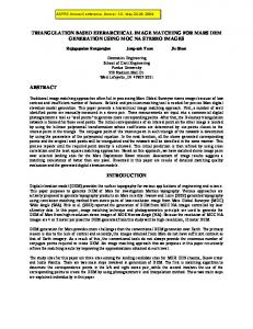
Fig. 4. (a) SEM picture of the MEMS switches at input matching network and (b) a close look of the switch.
Fig. 2. Schematics of the double-stub matching network for (a) input matching and (b) output matching.
Fig. 5.
Fig. 3. Process flow for the fabrication (a) evaporation of Cr/Au and liftoff, (b) PECVD of silicon nitride deposition and RIE etching, (c) sacrificial layer deposition and patterning, (d) sputtering of Au film and patterning, and (e) device release and CO critical point drying.
where is the imaginary part of the load impedance, is the . The equivalent capacicharacter admittance and tance of the two stubs can then be calculated as (4) The input and output matching networks are designed following this procedure. Fig. 2 shows the schematics of the two double-stub tuner on a Si substrate. The stubs are implemented with both fixed value MIM capacitors and MEMS capacitive switches. As reported in [8], the implemented MEMS shunt switch behaves as a shunt capacitor between the center conductor of the CPW line and the ground. The capacitance of the or by activating the switch can be varied to either switch. In the input matching network [Fig. 2(a)], the second has capacitance of 0.65 pF (provided by MIM capacstub itor 2) in one configuration and 2.15 pF in the other configuration. Due to the limitation of the down capacitance that a single switch can provide, two MEMS switches are used to provide 1.5 pF when they are pulled down. In the output matching network, both stubs are implemented by one MEMS switch with down-capacitance of 0.28 pF and 0.22 pF, respectively [Fig. 2(b)]. Since the loss introduced by the MEMS switch is quite low [8], the implemented matching network has very low loss even at high frequency range.
Pictures of the fabricated circuits.
III. FABRICATION PROCESS The fabrication process starts with a high resistivity Si subcm) covered with 2000 Si . strate (approximately 2000 m finite A lift-off process is applied to define the ground coplanar waveguide (FGCPW) lines, which are made of 200 of Cr and 8000 of Au. 2000 of silicon nitride is then deposited on the wafer with a PECVD process and a RIE process is followed to pattern the nitride layer. A sacrificial layer m is spin coated (SC1827 photoresist by Shipley) of about and patterned to form the anchor points for the switch and the openings for the MIM capacitor. This is followed by a sputtering m Au film. The Au film is then patterned to deposition of form the switch membrane and the top metal layer of the MIM capacitors. The process flow is illustrated in Fig. 3 and SEM pictures of the fabricated switches are shown in Fig. 4. After the circuit is fabricated, the ATF-34 143 transistor is mounted onto the wafer using conductive epoxy adhesive. Microscope pictures of the completed circuit are shown in Fig. 5. IV. MEASUREMENTS AND DISCUSSION The RF performance of both input and output matching networks was measured by a 8510C Vector Network Analyzer on an Alessi Probe Station with GGP Picoprobe 150 m pitch coplanar probes. The effects of the probes and the connecting cables were de-embedded by standard TRL calibration. The S-parameters of the matching network are shown in Fig. 6. Fig. 6(a) and (b) shows the response of the input matching network at two design configurations. At the 6 GHz configuration, both switches are pulled down. While at the 8 GHz configuration, both switches are up. Fig. 6(c) and (d)
LU et al.: MEMS RECONFIGURABLE MATCHING NETWORK FOR A CLASS AB AMPLIFIER
439
TABLE II SUMMARY OF THE POWER PERFORMANCE OF THE AMPLIFIER
The power gain and PAE of the amplifier were measured by connecting the input port to a HP 83624A Synthesized Sweeper and the output port to a HP 8564E Spectrum Analyzer. To calibrate the test setup, the circuit was replaced with a through line and the loss of the connecting cables and probes were measured. dBm, At the bias condition described in Section II and , , and of the amplifier were recorded at the two matching configurations. The power gain and PAE are calculated as Fig. 6. Measured and simulated response of (a) the input matching network at 6 GHz configuration, (b) the input matching network at 8 GHz configuration, (c) the output matching network at 6 GHz configuration, and (d) the output matching network at 8 GHz configuration.
(5) The results are shown in Fig. 7. Simulation results are also given in the figure. The PAE and gain are improved at high frequency when the matching network is switched from configuration 1 (6 GHz design) to configuration 2 (8 GHz design). Table II summarizes the Maximum Available Gain (MAG), simulated PAE, the measured gain and PAE at two peak frequencies. V. CONCLUSION We have demonstrated a reconfigurable amplifier design with maximum PAE and power gain at 6 GHz and 8 GHz. The adaptive matching networks are implemented with MEMS capacitive switches to provide matching conditions for both input and output at different frequencies. The RF responses of the matching networks at two design configurations are measured as well as the power performance of the amplifier. This technique can be applied to other circuit designs where reconfigurability of the circuit is required. REFERENCES
Fig. 7. The measured and simulated power performance of the reconfigurable amplifier (a) power gain and (b) PAE.
show the S-parameters of the output matching network. In the is up and the 6 GHz design configuration, the first switch is down (see Fig. 2). While at the 8 GHz second switch is down and is up. Both measured and configuration, simulated S-parameters are shown in this figure.
[1] G. Ferri, “Low-voltage low-power adaptive biased high-efficiency integrated amplifiers,” in Proc. IEEE 8th Int. Conf. Electronics, Circuits and Systems, vol. 3, 2001, pp. 1529–1532. [2] K. Nishikawa and T. Tokumistu, “An MMIC low-distortion variable-gain amplifier using active feedback,” IEEE Trans. Microwave Theory Tech., vol. 43, pp. 2812–2816, Dec. 1995. [3] G. M. Rebeiz and J. B. Muldavin, “RF MEMS switches and switch circuits,” IEEE Microw. Mag., pp. 59–71, Dec. 2001. [4] D. Peroulis, K. Sarabandi, and L. P. B. Katehi, “Low contact resistance series MEMS switches,” in IEEE MTT-S Int. Microwave Symp. Dig., vol. 1, June 2002, pp. 223–226. [5] E. R. Brown, “RF-MEMS switches for reconfigurable integrated circuits,” IEEE Trans. Microwave Theory Tech., vol. 46, no. 11, pp. 1868–1880, Nov. 1998. [6] K. L. Lange, J. Papapolymerou, C. L. Goldsmith, A. Malczewski, and J. Kleber, “A reconfigurable double-stub tuner using MEMS device,” in IEEE MTT-S Int. Microwave Symp. Dig., vol. 1, 2001, pp. 337–340. [7] D. M. Pozar, Microwave Engineering. New York: Wiley, 1998. [8] D. Peroulis, S. Pacheco, K. Sarabandi, and L. P. B. Katehi, “Tunable lumped components with applications to reconfigurable MEMS filters,” in IEEE MTT-S Int. Microwave Symp. Dig., vol. 1, June 2001, pp. 341–344.