A Software-Supported Methodology for Exploring Interconnection Architectures Targeting 3-D FPGAs Kostas Siozios, Vasilis F. Pavlidis†, and Dimitrios Soudris School of Electrical and Computer Engineering National Technical University of Athens Athens, Greece {ksiop, dsoudris}@microlab.ntua.gr Abstract—Interconnect structures significantly contribute to the delay, power consumption, and silicon area of modern reconfigurable architectures. The demand for higher clock frequencies and logic densities is also important for the FieldProgrammable Gate Array (FPGA) paradigm. Threedimensional (3-D) integration can alleviate such performance limitations by accommodating a number of additional silicon layers. However, the benefits of 3-D integration have yet to be sufficiently investigated. In this paper, we propose a softwaresupported methodology to explore and evaluate 3-D FPGAs fabricated with alternative technologies. Based on the evaluation results, the proposed FPGA device improves speed and energy dissipation by approximately 38% and 26%, respectively, as compared to 2-D FPGAs. Furthermore, these gains are achieved in addition to reducing the interlayer connections, as compared to existing design approaches, leading to cheaper and more reliable architectures. Keywords-FPGA; 3-D integration; interconnection architectures; CAD tools
I.
INTRODUCTION
Field Programmable Gate Arrays (FPGAs) have become the implementation medium for the vast majority of modern digital circuits. This situation makes the FPGA paradigm to grow in importance, as there is a stronger demand for faster, smaller, cheaper, and lower-energy devices. However, such performance enhancement is infeasible for modern technologies. A solution to this drawback can be achieved by three-dimensional (3-D) integration, which practically eliminates the long interconnects [12]. In order for such a technology to be widely accepted, several challenges need to be satisfied. For example, methodologies for architecture-level exploration are essential to design efficient devices, in terms of high performance and/or low energy. As these tasks are complex and time consuming, there is also a demand for CAD tools that facilitate the design of 3-D circuits. Recently many groups from academia [4, 6, 7, 11, 12], industry [8, 13] and research institutes [1] have put significant effort on designing and manufacturing 3-D systems. A survey of existing 3-D technologies is presented in [12], while the open issues for contemporary and upcoming fabrication processes are emphasized in [1]. A few companies [8, 13] develop 3-D ICs by stacking wafers, where the distance
978-3-9810801-5-5/DATE09 © 2009 EDAA
†
LSI-EPFL 1015 Lausanne, Switzerland
[email protected] between the layers is determined by the wafer thickness. The existing industrial research primarily concerns the manufacturing and fabrication of emerging 3-D technologies rather than the development of supporting CAD tools, which are mainly tackled by the academia. In [4], the potential of a 3-D FPGA, based on 3-D Switch Boxes (SBs), is evaluated using analytic models. The implementation of applications onto this architecture is supported by a CAD tool based on [10]. This approach has, however, several drawbacks. For instance, there is no restriction regarding the amount of interlayer connections. Finally, the assumption that each TSV is electrically equivalent to a wire placed within a layer with equal length, results in inaccurate solutions. A tool flow regarding the application implementation onto 3-D ICs is discussed in [6]. The placement algorithm is partitioning-based followed by a simulated-annealing refinement for minimizing the total wire-length. However, this approach does not investigate other important design issues, such as power/energy consumption, or the distribution of the power consumption throughout the 3-D stack. To summarize, in literature there are two main approaches for designing 3-D FPGAs. The first of these approaches includes devices, where all of the layers can be thought to be “functional layers” [4, 6], while in the second approach each of the layers is specialized (i.e., memory, switches, or logic) [11]. Although in this paper the investigated 3-D FPGA architectures contain identical logic resources in each of the layers (we are only interested in the interlayer communication schemes), heterogeneous FPGAs can also be explored. In this paper we propose a software-supported methodology for exploring and evaluating the effects of employing alternative 3-D technologies, on FPGAs. The contributions of this work are summarized, as follows: (i) we study the spatial distribution of interlayer connections across each layer onto 3D Virtex-based FPGAs, and (ii) we introduce a novel software-supported methodology for exploring and designing general-purpose interconnection architectures targeting 3-D FPGAs with a reduced number of interlayer wires. Our methodology results in a general-purpose 3-D FPGA that exhibits similar improvements in performance, as compared to existing design approaches, but it requires fewer interlayer connections. From 3-D fabrication/manufacturing
point of view, fewer interlayer connections means: (i) smaller fabrication cost and (ii) larger useful silicon area in each layer (an interlayer contact occupies considerably more silicon area than a simple metal contact). Experimental results demonstrate the efficiency of the proposed 3-D FPGA architectures. More specifically, the presented FPGA device achieves performance improvement, in terms of speed and energy dissipation of approximately 38% and 26%, respectively, as compared to 2D FPGAs. Additionally, fewer interlayer resources are used, resulting in cheaper and more reliable devices. The remainder of the paper is organized as follows. In Section II, we describe the modeling of the 3-D FPGA, while the proposed architecture level exploration methodology is presented in Section III. In Section IV, we derive the architectural characteristics of the 3-D FPGA and a comparison between existing 2-D and 3-D FPGAs is performed. Finally, the main points of the paper are summarized in Section V. II.
MODELING OF THE 3-D FPGA ARCHITECTURE
Our target device consists of multiple functional layers, while the interlayer connectivity is provided by vertically aligned SBs. For our case study, the functionality of the employed SBs is similar to the SBs in Xilinx FPGAs [10]. Two different types of SBs are used. The first is a 2-D SB, where an incoming routing track can be connected to wires in 3 within the same layer, the three other directions whereas the latter type of SB supports also connections to the 5 . For the third dimension (upper and lower layers) topmost and lowest layers of a 3-D stack the SBs have 4. The 2-D SB is formed by 6 transistors, while the 3-D SB requires 15 transistors, where denotes the width of the routing channel. As discussed later, the increased number of transistors inside the 3-D SBs affects both the device performance and fabrication complexity. Consequently, the total number and the spatial location of the 3-D SBs in each layer should be chosen carefully. Three means of interlayer communication are investigated. We evaluate the wire-bonding, the Face-to-Face (denoted as F2F), and the Face-to-Back (F2B or TSV) technologies. Note that the F2F approach is applicable only to 3-D devices composed solely of two layers. Regarding the spatial distribution of interlayer connections in the wire-bonding approach, the 3-D SBs are assigned to the periphery of each layer, while for the F2F and F2B technologies, the 3-D SBs can be assigned anywhere across the area of a layer. III.
(iv) the evaluation of the implementation of the application onto the derived 3-D FPGA device. To the best of our knowledge, this toolset is the first complete framework (starting from an HDL description down to the generation of the configuration file) in academia for exploring and supporting the implementation of applications onto full-custom 3-D FPGAs.
EXPLORATION METHODOLOGY FOR 3-D FPGAS
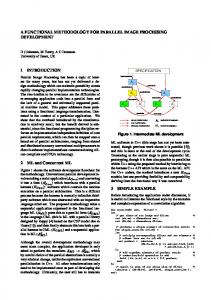
In this section we provide a detailed description of the proposed methodology for building 3-D FPGAs. The methodology to explore and evaluate interconnection structures within 3-D FPGAs is depicted in Figure 1. A tool flow that embodies this methodology named 3-D MEANDER Framework has been developed [5]. The proposed methodology consists of four stages: (i) the application partitioning, (ii) the selection of parameters related to the 3-D architecture, (iii) the physical design of the application, and
Figure 1. The proposed methodology for exploring 3-D FPGAs.
The first step of the proposed methodology deals with application partitioning. Initially, the application is partitioned to a number of sections, which is at least equal to the layers comprising the target 3-D FPGA. Then, these sections are grouped together based on specific features (i.e., their functionality) of the architecture (or application). After the grouping task, we assign the resulting partitions to the physical layers. During this task, one (or more) partition(s) is (are) assigned to each of the 3-D FPGA layers. Finally, the last task of the first step deals with the layer ordering. The results of the first step are crucial for achieving cheaper and more reliable 3-D architectural solutions. For instance, by reducing the number of signals that cross multiple partitions, we achieve higher utilization ratios for the fabricated interlayer connections. More specifically, for our study, the term utilization ratio is described by Equation (1) .
(1)
In order to automate the first step of the proposed methodology, we employ the CAD tool presented in [5]. In contrast to existing approaches [3, 9], which focus on reducing the interlayer communication, our algorithm exhibits higher flexibility, as the cost functions can be tuned to satisfy the specifications of the systems. Then, a high-level estimation, based on the demand of the interlayer connectivity, is performed to determine the efficiency of the resulting application partitioning. Based on the design goals, the derived partitioning is either accepted or not. If an acceptable solution is derived, we proceed to the second step of our proposed methodology; otherwise the application is fedback to the first step for further improvement.
The output of the first step produces some guidelines regarding the demand of the interlayer communication fabric. This information is appropriately extracted and analyzed from the proposed methodology during the second step. More specifically, by studying the performance enhancement of numerous applications implemented onto 3-D FPGAs, where the interlayer connectivity is provided through one of the available integration technologies (i.e., wire-bonding, F2F, and F2B), we determine both the total number of the actually required 3-D SBs, as well as their spatial distribution across each layer. Additionally, during the second step we also select the VLSI process technology for fabricating each of the functional layers that form the 3-D FPGA device. During the third step of the proposed methodology, the application is floor-planned, placed and routed (P&R) onto the selected 3-D FPGA. Each of these tasks is performed simultaneously for all of the device layers, in order to appropriately propagate constraints among layers. This step is implemented by our P&R tool, named 3DPRO [5]. Similar to the output of the first step, after the physical implementation there is a conditional statement that checks the quality of the P&R of the application. If the gains of the resulting implementation are not acceptable, there is a feedback for additional improvements. Finally, the efficiency of the resulting implementation of the application is evaluated through several design parameters. These parameters include the maximum operating frequency, the power/energy consumption, as well as the of the interlayer communication fabric. IV.
DESIGNING HETEROGENEOUS 3-D FPGAS
In this section we provide the results of the architecturelevel exploration of heterogeneous 3-D FPGAs. This heterogeneity is based on three concepts. We study the effect of employing layers composed by a limited number of 3-D SBs (as compared to existing approaches [4, 6]), while the spatial assignment of 3-D SBs across each layer is determined based on previous results [5]. We also discuss the usage of alternative bonding technologies in order to build the 3-D FPGA (namely TSV, F2F, and wire-bonding). Finally, we analyze a scenario where the layers of the 3-D FPGA are fabricated with different VLSI process technologies (ranging from 45 nm up to 180 nm). A. Investigate the demand for interlayer connectivity In order to investigate the actual demand for interlayer connectivity, Figure 2 visualizes this parameter across a 3-D FPGA consisting of three functional layers. Based on the results depicted in this figure, we conclude that the demand for interlayer communication varies between two arbitrary points , , and , , of the FPGA device, even for 3-D SBs placed on adjacent spatial locations within the same layer. More specifically, the utilization ratio of vertical connectivity gradually decreases from the center of each layer to the periphery or from the middle of the 3-D stack to the top/bottom layers. This occurs due to the inherent feature of
the placement algorithms that physically map the applications from the center of each layer to its periphery (as at the center of the layers there are more degrees of freedom to reduce the perimeter of the bounding-box).
Figure 2. Variation of the demand for interlayer connections.
Ideally, we have to employ a continuously varying density of interlayer connectivity at each , , point of the 3-D architecture, producing a totally irregular device. In order to avoid such an ASIC-based design, we introduce a piecewise homogeneous interconnection architecture consisting of a few regular regions. By selecting to design each of the layers with the same percentage as well as distribution of 3-D SBs across the layers, (rather than making separate masks for each of them), we achieve to reduce significantly the fabrication cost. B. 3-D architectures with limited interlayer connections An example of defining the regions with different density of interlayer fabric is illustrated in Figure 3. This layer consists of slices which are divided into two regions based on the spatial/statistic results of the actual utilization of interlayer connections, as shown in Figure 2. The distribution of 3-D SBs onto this layer is described by the vector 1,2 , where the values of this vector denote the Manhattan distance between successive 3-D SBs belonging to region . To determine the exact spatial locations of the distributed interlayer routing fabric for F2F or F2B technologies, we apply the following procedure: Initially, we assign a 3-D SB on a spatial location , , . For each of the already assigned 3-D SBs the four neighbors of each SB are successively placed , , , , , , , , to the locations , , respectively. is the corresponding value and , of the vector of the initially assigned 3-D SB. For the wirebonding approach, we have determined that the optimal distribution of 3-D SBs (across the layer periphery) is described by vector 2. The values of the vector are determined after evaluating a representative number of applications belonging to different application domains. The vectors, however, can differ if the 3-D FPGA targets specific application-domain solutions (i.e., DSP and multimedia). The proposed approach should not be thought as a SB depopulation technique, as there is no SB removal. More specifically, starting from a device where the layers have solely 2-D SBs, we selectively assign 3-D SBs on parts of the layers (based on an approach similar to that shown in Figure
3). The resulting FPGA device consists of a combination of 2D and 3-D SBs. The formed 3-D FPGA is characterized by factor (described by Equation (2)), which defines the percentage of 3-D SBs over all the SBs of the device %
.
3D
2D
3D
2D
3D
2D
3D
3D
3D
2D
3D
3D
3D
3D
3D
(2)
performance. For instance, F2B or TSV technologies result in greater improvement in performance, as compared to 3-D FPGAs with wire-bonding technology consisting of a larger number of layers. As the number of device layers is directly related to the fabrication cost, fewer layers result in cheaper products. Consequently, the tradeoffs between the improvement in performance, design complexity and cost due to alternative bonding technologies should be carefully considered.
2D
3D
3D
3D
2D
3D
2D
3D
2D
3D
Region1
Normalized Delay
Region2
Figure 3. Abstract view of the proposed 3-D SB distribution over layers.
C. Investigate the impact of using alternative bonding technologies In this paragraph we investigate the impact of using 3-D FPGAs, where the bonding technology among layers is either wire-bonding, TSV, or F2F. The employed experimental setup can be summarized, as follows: • The 3-D FPGA consists of up to four functional layers. • The hardware resources among layers are identical. • The interlayer connections are realized inside 3-D SBs. • The RLC parameters (shown in Table I) for the interlayer fabric are extracted from the state-of-the-art solutions published in literature [8, 15]. TABLE I.
CHARACTERISTICS OF THE ALTERNATIVE 3-D TECHNOLOGIES
Wire-bonding [15] Length: 1 mm Inductance: 2 nΗ Capacitance: 0.3 pF
F2F [8] Diameter: Min. Pitch: Resistance: Capacitance: Height:
1.7um 2.4um 0.15Ω 0.25fF 4-9um
F2B [8] Diameter: 1.2 um Min. Pitch: 4 um Resistance: 0.35 Ω Capacitance: 2.5 fF Height: 4-9 um
Figure 4 plots in normalized manner (over the 2-D architecture) the variation of delay with energy consumption for 3-D FPGAs with three different integration technologies (wire-bonding, F2F, and F2B), and different number of layers. A number of conclusions can be derived from this graph. For specific 3-D technologies, the increase in device layers results in energy savings and delay reduction. Additionally, given the number of layers, a 3-D device with TSV or F2F technology outperforms the wire-bonding technology. Furthermore, our results indicate that the improvement in performance is a strong function of the manufacturing technology. Alternatively, the number of layers of the 3-D FPGA comparatively offers a smaller improvement in
Figure 4. The Pareto solutions for evaluating alternative 3-D FPGA devices in terms of delay and energy consumption.
Based on the results provided in Figure 4, the architecture with minimum delay and energy consumption contains four layers, where a TSV manufacturing technology is used. This architecture, marked as “Optimal architecture” in Figure 4, achieves the maximum gains in delay and energy consumption. More specifically, this device reduces the delay and the energy consumption by almost 75% and 67%, respectively, as compared to a conventional 2-D FPGA with identical hardware resources. Alternatively, the design complexity of building 3-D FPGAs can be significantly improved by either decreasing the number of layers and/or using another bonding technology. These alternative approaches encompass a small penalty in the speed and energy consumption of the system. Therefore, in Figure 4 we group a number of 3-D FPGAs that exhibit comparable performance metrics as compared to the optimal architecture. By varying the delay and energy consumption of up to 15% and 25%, respectively, we consider devices (inscribed within a dotted rectangular) consisting of fewer layers, while exhibiting comparable performance. As we are interested in applying the proposed methodology to design a general-purpose 3-D FPGA, we select as a case study a device which exhibits the following features: (i) high operating frequencies (or smaller delay), (ii) low energy consumption, and (iii) reduced design complexity. Based on
these criteria, the architecture marked in Figurre 4 as “Optimal” exhibits superior performance regarding critteria (i) and (ii); however, the increased design complexity of this device mal solution. composed of four layers results in a non-optim Consequently, we choose as a case study, a 3-D FPGA with three layers interconnected with a TSV ttechnology. This device, shown as “Selected architecture” in F Figure 4, exhibits comparable performance metrics with the “Optimal architecture” (average increase in delaay and energy consumption of almost 13% and 8%, resppectively), while requiring fewer layers. D. Investigate the impact of employing differeent VLSI technologies Next, we study the impact of fabricatinng the functional layers of the 3-D FPGA with differentt VLSI process technologies, ranging from 45 nm up to 1180 nm. In this experiment we evaluate the gains of using deevices consisting of up to four layers, while the bonding techhnology provided either by wire-bonding, F2F, or TSV. For sake of completeness, we also provide results for convventional (i.e., 2D) FPGA devices. The results of this comparison are summarized in Figure 5. The vertical axis of this figure demonstrates the normalized EDP over the maximum EDP among alternative implementations, while thee horizontal axis corresponds to the alternative 3D architecturess.
E. Investigate the percentage of utiilized interlayer connections In order to investigate the percentage of actually utilized interlayer connections, we employ a scenario where all of the SBs can form connections to the adjacent layers (i.e., 3-D SBs). This architecture is the existiing approach for designing 3-D FPGAs [4, 6]. However, as sho own in Figure 2, the actual demand for interlayer connections is i not uniformly distributed across the layers of the 3-D stack. Based on previous results 3 FPGA is composed of [5], we have shown that when a 3-D three layers and 30 % 3-D SBs, S the interlayer routing resources are more efficiently utilized. neous interconnect fabrics To demonstrate that heterogen (combination of 2-D and 3-D SB Bs) produce comparable or superior performance as com mpared to homogeneous interconnect fabrics in 3-D FPGAs, the proposed methodology has been evaluated on the 20 largest MCNC benchmark plications are implemented applications. These benchmark app on two 3-D FPGAs, each of whicch consists of three layers (designed in 90nm CMOS techno ology) and the same logic resources but with a different number n of 3-D SBs (i.e., different K). The vertical axis in Figure F 6 corresponds to the utilization ratio of interlayer co onnections, over the total fabricated interlayer connections. The results showing the perceentage of actually utilized interlayer connections (denoted ass % ) are summarized in Figure 6. Based on these results, the percentage of utilized interlayer connections for architeectures consisting of 30% and 100% 3-D SBs is i about 43% and 46%, respectively. This result shows that the utilization ratio for this a constant, if these type of routing resources is almost connections exceed a minimum density d threshold, which is required for the application to be routable.
Figure 5. Comparison in terms of EDP for the 3-D F FPGAs at different technology nodes.
Based on Figure 5, we can conclude that technology scaling offers higher improvements for both 2-D andd 3-D FPGAs. In addition, the relative gains of fabricating a 3-D chip in advanced VLSI technologies are practically iinvariable among different bonding approaches. Thus, 3-D FP PGAs with fewer layers can achieve comparable improvementt in performance as compared to other 3-D architectures fabriicated with more layers but at an older technology node. Thiss tradeoff can be useful to decrease the fabrication cost, sinnce older VLSI technologies are cheaper, and they offer higheer yield.
Figure 6. Comparison results of the 20 2 largest MCNC benchmark applications: Via utilization in a 3-D FPGA A architecture (with K = 30% and K = 100% [4 4]).
In other words, the intercon nnection network is not significantly improved by inco orporating more vertical connections (i.e., by replacing 2-D 2 SBs with 3-D). This behavior occurs due to the ineefficiency of the routing
algorithms to manage the additional interlaayer connection, beyond a specified threshold density. In order to exhaustively evaluate thhe behavior of architectures with fewer interlayer connectioons, we provide experimental results for another two 3-D F FPGAs. Each of these 3-D FPGAs consists of three layers, asssuming a 90 nm CMOS technology, while the interlayer coommunication is provided through TSVs. These alternative 3--D FPGAs differ in the amount of 3-D SBs placed on each laayer. We explore the efficiency of implementing various applications, in terms of EDP, onto the proposed 3-D FPGAs wiith 30%, as compared to a scenario where 100% . For shake of completeness, we also provide results for 22-D FPGAs with identical logic resources. The comparison resuults are provided in Figure 7.
g the amount of interlayer achieved in addition to decreasing connections, as compared to existin ng design approaches for 3D FPGAs. Thus, new opportunitiees for improving the yield and reducing the design complexitty of 3-D FPGAs emerge. Finally, we demonstrate that 3-D FPGA devices with fewer interlayer connections exhibit simiilar efficiency (in terms of EDP) with FPGA devices that contain c significantly more interconnection resources. MENTS ACKNOWLEDGM This work was partially supported d by the MOSART project (Mapping Optimization for Scalablee multi-core ARchiTecture) funded by the EU (IST-215244), http://www.mosartproject.org.
REFEREN NCES [1] [2] [3] [4] [5]
[6]
Figure 7. Comparison results in terms of EDP for the MCNC benchmark applications: Implementation in 2-D and 3-D FPGAs witth three layers where K = 30% and K = 100% [4] of interlayer communiication fabric.
From this figure, the 3-D architectures achieeve average EDP reduction, as compared to conventional (i.ee., 2-D) FPGAs, ranging from 55% (for the “Proposed” archhitecture) to 62% for an architecture with 100%. These ressults demonstrate that the proposed methodology for designing 3-D FPGAs with a reduced number of 3-D SBs, as well as the supporting CAD tools from the 3-D MEANDER Framewoork, can achieve comparable performance improvements with existing m connections to approaches [4, 6] where all of the SBs can form the adjacent layers. However, the fewer interllayer connections result in a decrease in fabrication cost. V.
[7]
[8]
[9]
[10] [11] [12] [13]
CONCLUSIONS
A systematic methodology for exploringg and evaluating alternative 3-D FPGA architectures is presented. The DER Framework. methodology is supported by the 3-D MEAND The proposed methodology was applied to evaaluate alternative 3-D bonding styles (i.e., wire-bonding, F F2F, TSV) and technology nodes (ranging from 45nm up to 180nm). The experimental results show that the propossed 3-D FPGAs achieve performance improvements in term ms of delay and energy dissipation of almost 38% and 26%,, respectively, as compared to 2-D FPGAs. Additionally, these gains are
[14]
[15]
E. Beyne, “3-D interconnection and Packaging: Impending Reality or still a Dream?,” Conf. Solid-State Circcuits, pp. 138-139, 2004 Benchmarks from Microelectronics Center of North Carolina J. Roy et al., “Min-cut Floorplacem ment,” IEEE Trans. on ComputerAided Design, vol. 25, no. 7, pp. 1313-1326, 2006 C. Ababei et al., “Placement and Ro outing in 3-D Integrated Circuits,” IEEE Design and Test, Vol.22, No.6, pp. 520-531,2005 K. Siozios, A. Bartzas, and D. D Soudris, “Architecture-Level Exploration of Alternative Intercon nnection Schemes Targeting 3D FPGAs: A Software-Supported Metho odology,” International Journal of Reconfigurable Computing, Vol. 2008, Article ID 764942, doi:10.1155/2008/764942 S. Das et al., “Technology, Performaance, and Computer Aided Design of Three Dimensional Integrated Circuits,” C Int. Symp. on Physical Design, pp. 108-115, 2004 A. Rahman et al., “Wiring Requ uirement and Three-Dimensional Integration Technology for Field Pro ogrammable Gate Arrays,” IEEE Trans. on VLSI, Vol. 11, No 1, pp. 44 4-54, 2003 S. Gupta, M. Hilbert, S. Hong, and R. Patti, “Techniques for Producing 3-D ICs with High-Density Interconn nect,” Int. Conf. VLSI Multi-Level Interconnection Conference, 2004 N. Selvakkumaran and G. Karypiis, “Multiobjective HypergraphPartitioning Algorithms for Cut an nd Maximum Subdomain-Degree Minimization,” IEEE Trans. on CAD C of Integrated Circuits and Systems, Vol. 25, No. 3, pp.504-517, March M 2006 V. Betz, J. Rose, and A. Marquardt, “Architecture “ and CAD for DeepSubmicron FPGAs,” Kluwer Academiic Publishers, 1999. M. Lin et al., “Performance Benefitss of Monolithically Stacked 3-DFPGA,” Int. Symp. on FPGA, pp. 113-122, 2006 V. F. Pavlidis and E. G. Friedman n, “Three-Dimensional Integrated Circuit Design,” Morgan Kaufmann Publishers, P 2009 A. Topol et al., “Three-Dimensional Integrated Circuits,” IBM Journal Resources & Development, Vol. 50, 2006 K. Leijten-Nowak and J. van Meerberrgen, “An FPGA Architecture with Enhanced Datapath Functionality,” Int. I Symp. on FPGA, pp.195-204, 2003 C.-T. Chiu, S.-M. Wu, and C.-P. Hung, “High Speed Electrical Performance Comparison between Bump B with RDL and Wire Bond Technologies,” Int. Symp. on Electronic Materials and Packaging, pp. 83-88, 2002