Norma: A Hierarchical Interconnection Architecture for Network on Chip Akram Reza
Midia Reshadi
Ahmad Khademzadeh
Maryam Bahmani
Islamic Azad University, Science and Research Branch Tehran-Iran
[email protected]
Islamic Azad University, Science and Research Branch Tehran-Iran
[email protected]
Iran Telecommunication Research Center Tehran-Iran
[email protected]
Islamic Azad University, Science and Research Branch Tehran-Iran
[email protected]
Abstract— NoC is a potent solution to address design complexity and productivity problems whose its key component is the interconnect architecture which directly affects both cost and performance parameters. The purpose of this paper is to present the basic ideas behind the development of our new hierarchical Network-on-Chip (NoC) architecture, called “Norma” that its most distinguished characteristic is its hierarchical nature. We present two types of Norma, Norma-I and Norma-II which have been compared to 2D Mesh. Results illustrate that Norma-I and Norma-II have far more proper functionality than 2D Mesh, when 75 percent of whole traffic interacts in each subnet.
I.
INTRODUCTION
The growth of the modern semiconductor technologies miniaturization, scalability problems, and interconnection complexities in chip design create a requirement for highly efficient system-level design methodologies [1-2]. Due to this, Network on Chip has been presented to solve these problems as a packet-based on chip communication networks [3-5]. Fundamentally, topology as a key element of NoC architecture affects on several critical cost and performance parameters [6]. Principally, combination of a localized, hierarchical and modular topology and a proper methodology to map the applications on the resources (IP blocks) based on their interactivities brings about an efficient NoC infrastructure. The fundamental result of this is to limit the communication distances between resources, which leads to smaller hop count, low latency, and far less power consumption [6]. Although, NoC topologies would prefer to support flexibly different applications, optimized topology is contrived when designers are definitely familiar with the characterizations of applications traffic. Furthermore, profitable effects of a topology are illustrated when a specific methodology for mapping of applications to the cores is presented particularly. In this contribution, a hierarchical communication-centric system architecture called “Norma” is described. Two different types of Norma, Norma-I and Norma-II, are compared to 2D Mesh in terms of number of packet loss, average latency, and area consumption.
978-1-4244-3478-7/08/$25.00 ©2008 IEEE
The findings of present paper indicate that, in the presence of localized traffic that 75 percent of its interactivities are limited in each subnet, Norma topologies play far more effective roles in terms of average latency and packet loss in comparison to 2D Mesh. Furthermore, area consumption is reduced 48% in Norma-I and 17% in Norma-II compared with 2D Mesh. This paper is organized as follows: Norma architecture is presented in section 2. Next, Norma addressing and routing are focused on section 3 and 4 respectively. After this, Norma router is presented in section 5 and section 6 covers the experimental results. Finally, we conclude our paper in section 7. II.
NORMA ARCHITECTURE
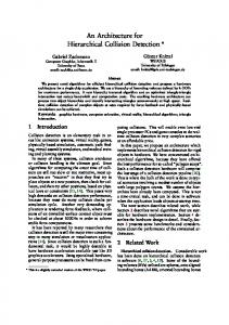
Norma is a hierarchical ring-based interconnected topology which connects localized subnets with each other via global routers (switches) in the backbone. As can be seen in Fig.1.a and Fig.2.a Norma is categorized into two types: Norma-I and Norma-II. In Norma-I, four IPs are attached to just one local switch (LS) in each subnet and the local switch is connected to one single global switch (GS) in the backbone (see Fig.1.a). Unlike Norma-I, in Norma-II multiple routers and resources can be placed in each subnet (see Fig.2.a). Another significant difference between Norma-I and Norma-II is the number of ports in routers. Specifically, In Norma-I, number of ports of GS is five in the intermediate backbone rings and four in the inner and outer backbone rings (see Fig.1.b). Also, when we have just one backbone ring, port number of GS is three (see Fig.1.a). Moreover, number of ports of LS is five in each backbone ring (see Fig.1.a and Fig.1.b). As opposed Norma-I, Norma-II has just four ports routers as both LS and GS (see Fig.2.a, Fig.2.b, Fig.2.c, and Fig.2.d). Fundamentally, “Network on Chip topologies can be described by a graph G ( N , C ) , where N is the set of switches, and C is the set of channels between switches” [5]. In NormaI and Norma-II, N is divided into LS and GS. (LS)s are responsible for intra-subnet switching while (GS)s are accountable for inter-subnet packet transmission in backbone.
Fig. 1.b Norma-I topology with 32 IP cores
Fig. 1.a Norma-I topology with 16 IP cores
It is worthwhile that Incremental expandability in a topology is not powered by 2 and the core count grows linearly [7]. The number of cores (IPs) is increased in Norma-I linearly as “(1)” where i is the number of backbone rings in Norma-I. = 16 ´ i . (1) Norma - I Also, the number of routers (switches) ( N Norma- I ) is Core
calculated as “(2)”. N = 4´ 2´i = 8´i . (2) Norma - I Every ring has four subnets and every subnet has two switches (local and global). In addition, the number of links ( C Norma - I ) is grown as “(3)”. C
= 8 + ((8 + 4 ) ´ (i - 1)) = 8 + (12 ´ (i - 1)) . (3)
Norma - I Fig.2.a presents the Norma-II topology. As previously mentioned, in Norma-I local switches have five ports while global ones have three ports, when the number of cores is 16. This ends in a big gap between local and global switches operational frequency, because five ports switches are approximately 5 times slower and 3 times larger than three ports switches (see TABLE.III). To fill this gap, in Norma-II every switch has four ports whether local or global. This brings about a balanced speed and area between local and global switches. The number of cores (IPs) is increased in Norma-II linearly as “(4)” Where j is the number of local switches in the subnets of Norma-II. Core = 8´ j . (4) Norma - II Also, the number of switches in Norma-II ( N Norma - II ) is calculated as “(5)” Where k o and k e show the sequence of odd or even value of j . For instance, j = 5 is the 3rd natural odd number
( (
) )
ìï4 + 4 ´ j - 2 + ko ; j = 1,3,5,...; ko = 1,2,3,... = N Norma - II í4 + 4 ´ j - 1 + k ; j = 2, 4,6,...; k = 1, 2,3,... ïî e e .
(5)
C In addition, the number of links in Norma-II ( Norma - II ) is grown as “(6)”. ì4 + 4 ´ (2 ´ j - 2 ); j = 1,3,5,7,... C =í Norma - II î4 + 4 ´ (2 ´ j - 1); j = 2,4,6,8,... . (6)
Norma-I expandability is presented in Fig.1.b and the procedure of Norma-II expandability is shown in Fig.2.b, Fig.2.c, and Fig.2.d III.
NORMA ADDRESSING
In order to transmit packets of IP cores across the NoC, unique address must be assigned to each reachable destination. In both Norma-I and Norma-II, switches just like IP cores have their own unique addresses. Due to the fact that, switches may want to communicate some control messages with each other without IP cores disturbance. Five bits addresses can address 8 switches and 16 IP cores in Norma-I and 12 switches and 16 IP cores in Norma-II. Structural and hierarchical design of Norma-I and Norma-II leads to simple addressing scheme which is presented in Fig.1.a and Fig.2.a for Norma-I and Norma-II respectively. Structural addressing of Norma-based topologies makes shortest path routing algorithm efficient and fast and ends in compact and condensed routing logic in switches. Particularly, addressing schemes of subnet (0) in Norma-I and Norma-II are demonstrated in TABLE.I and TABLE.II, respectively for 16 IP cores. As it can be seen, two most significant bits in both Norma-I and Norma-II addresses refer to the subnet number. Third bit in Norma-I and Norma-II addresses demonstrates whether the object is switch (addr
R
R
LS
LS
LS
R LS
GS
LS
GS
R R
LS
R
LS
GS
LS
GS
LS
LS
LS
LS
Fig. 2.b Norma-II topology with 24 IP cores Fig. 2.a Norma-II topology with 16 IP cores
Fig. 2.c Norma-II topology with 32 IP cores
(2)=’0’) or IP core (addr (2)=’1’). Two least significant bits illustrate four IP cores in each subnet. IV.
NORMA ROUTING
The NoC routing mechanism is accountable for efficient packets routing from source to destination. “The routing protocol deals with resolution of the routing decision made at every router” [5]. Routing method affects cost (area and power consumption) and performance (average latency) issues in the NoC design. Norma-based topologies routing is very simple, due to their constructive architectures and addressing schemes. Norma-based routing protocols select shortest path between source and destination node and perform hierarchically.
Fig. 2.d Norma-II topology with 40 IP cores
Namely, routing decisions in global switches just are determined based on two most significant bits of the addresses, which refer to subnet number. Therefore, in global switches routing logic, only the subnet of the destination is determined. Also, the subsequent routing decisions are made in local switches level. In addition, local switch routing logic determines whether the destination is located in the same subnet or not, by comparing the two most significant bits of addresses. If the destination and current switches are not located in the same subnet, global port (LS to GS) is selected as the destination port. Otherwise, both destination and current switches are in the same subnet. Third bit of the destination address (addr(2)) clarifies the destination type which can be switch or IP core. Moreover, two least significant bits make clear the exact IP core port in the local switches. As previously mentioned, Norma-based routing
TABLE I NORMA-I ADDRESSING SCHEME
#
Address
Object
Subnet- Name
addr(4,3)
addr(2)
addr(1,0)
0 1 2 3 4 5 6 7
00000 00001 00010 00011 00100 00101 00110 00111
Local Switch-0 Reserved Reserved Global Switch-0 Core-0 Core-1 Core-2 Core-3
Subnet-0 Subnet-0 Subnet-0 Subnet-0 Subnet-0 Subnet-0 Subnet-0 Subnet-0
00 00 00 00 00 00 00 00
0 0 0 0 1 1 1 1
00 01 10 11 00 01 10 11
TABLE II NORMA-II ADDRESSING SCHEME
#
Address
Object
Subnet-Name
addr(4,3)
addr(2)
addr(1,0)
0 1 2 3 4 5 6 7
00000 00001 00010 00011 00100 00101 00110 00111
Reserved Local Switch-0-1 Local Switch-0-2 Global Switch-0 Core-0 Core-1 Core-2 Core-3
Subnet-0 Subnet-0 Subnet-0 Subnet-0 Subnet-0 Subnet-0 Subnet-0 Subnet-0
00 00 00 00 00 00 00 00
0 0 0 0 1 1 1 1
00 01 10 11 00 01 10 11
algorithms perform based on shortest path choice, in order to this there are some situations in routing that two or more paths have no difference in hop count and just the intermediate nodes are discrepant. For example, when a packet wants to reach the GS2 from the GS0 (see Fig.1.a and Fig.2.a). In such situations, proposed routing algorithms, in Global switches (GSs), forward packets in the backbone rings and distribute the flits uniformly in clockwise direction or counter clockwise direction, in order to alleviate the power consumption and congestion. V.
NORMA ROUTER
To validate the area of Norma topologies, Norma-I and Norma-II, and 2D Mesh, a prototype router (switch) has been described in VHDL and synthesized in “Leonardo Spectrum 2005” in “130nm” ASIC. Wormhole routing mechanism is chosen, due to its several advantages such as less area consumption. Our described router has a central unit for routing decisions. In addition, packets port granting is first come, first serve basis (FIFO). Furthermore, input buffering in each port is contrived, in order to lessen the switch area. Handshaking flow control is applied in inter switch connections. VI.
EXPERIMENTAL RESULTS
In this section, the simulation results of Norma-I and Norma-II in comparison to 2D Mesh are illustrated from the performance and cost point of views. The two measured performance indicators were “average latency”, and ”packet loss”; in addition, “area” is chosen as a cost indicator. Lacking specific tools for evaluating networks on chip, the performance of NoC architectures leads us to use Network Simulator (NS-2) [8]. In [9] and [10] the authors use the NS2 for different performance metrics comparing different architectures. Every topology has been evaluated with 16 IPs.
We use CBR traffic pattern, which generates traffic according to a deterministic rate [11]. Packets have constant size (256 flits). Every flit is one byte. Due to high level simulation simplification, no flow control mechanism has been used. In order to this, packet loss becomes a critical performance parameter, which has to be analyzed. Moreover, we use “Localization Factor” which has been introduced in [12]. The Localization Factor (LF) is the ratio of local traffic to total traffic. For example, if the LF is 0.75, then 75 percent of the traffic generated by an IP occurs within its cluster, while the rest of the traffic is randomly distributed in the remainder of the entire NoC. Consequently, we use both 0.75 and 0.5 LFs to emulate the behaviors of different applications and traffic in the topologies. Based on the hop count between source and destination and the routing algorithm, each message may have a different latency [11]. For instance, if LF equals 0.75, the average hop counts are 3, 3.25, and 4.25 for Norma-I, NormaII, and 2D Mesh respectively and if LF equals 0.5 the average hop counts are 3.75, 4.25, and 4.75 for Norma-I, Norma-II, and 2D Mesh respectively. The difference between Norma-I and Norma-II hop count values is because of an external link in each Norma-II subnet. “Latency” and “Packet loss” are defined in [12] [13]. Fig.3.a and Fig.3.b reveal the latency variation for specified topologies with 0.75 and 0.5 LFs. It is clear from the figures that Norma-I has the least average latency due to its least values of hop counts. Fig.3.c and Fig.3.d demonstrate the reduction of packet loss by the growth of buffer size for described topologies when LF equals 0.75 and 0.5 respectively, when the injection rate of each resource equals 980 Mbps. As can be seen, Norma-II has the smallest value of packet loss. This happens because in each subnet Norma-II has two local switches while Norma-I has just one local switch. In Norma-I, local switches are bottleneck points. Especially when LF equals 0.5, half of the transactions between resources are inter-subnet, Norma-I has the most packet loss value in
2D Mesh Norma-I
3
2 1.5 1
Norma-II
3.5 3 2.5 2 1.5 1
0.5
0.5
0
0 400
500
600
700
800
900
400
500
Injection rate (Mbps)
800
900
Packet Loss (LF=0.5) 3000
2D Mesh
2000
Norma-I
1500
Norma-II
1000 500
Total Packet Loss (packet)
Total Packet Loss (packet)
700
Fig. 3.b Average latency Vs. Injection Rate (LF=0.5)
Packet Loss (LF=0.75)
2500
600
Injection rate (Mbps)
Fig. 3.a Average latency Vs. Injection Rate (LF=0.75)
2500
2D Mesh
2000
Norma-I
1500
Norma-II
1000 500 0
0 4
6
8
10
4
12
400000
2D Mesh
12
THE OPERATIONAL FREQUENCY AND AREA CONSUMPTION OF SWITCHES
Norma-I Norma-II
10
TABLE III EFFECTS OF PORT NUMBER ON
Area vs. Buffer Size 500000
8
Fig. 3.d Packet loss Vs. Buffer size (LF=0.5)
Fig. 3.c Packet loss Vs. Buffer size (LF=0.75)
600000
6
Buffer size (Flit)
Buffer Size (Flit)
Number of Gates in ASIC 130 nm
Average Latency (LF=0.5)
Norma-I
4 Average Latency (µs)
Norma-II
2.5
Average Latency (µs)
2D Mesh
Average Latency (LF=0.75)
3 ports switch 4 ports switch 5 ports switch
300000
Normalized frequency 1 0.6 0.18
Normalized area 0.3 0.7 1
200000
VII. CONCLUSION
100000 0 4
6
8
10
12
Buffer size (Flit)
Fig. 3.e Area consumption of evaluated topologies Vs. buffer size
comparison to 2D Mesh and Norma-II (see Fig.2.d). Due to this, Norma-based topologies are particularly valuable in localized loads. Fig.3.e shows the required number of gates in Norma architectures compared with 2D mesh. As can be seen, Norma-I has the least area according to less router and links count.
In this paper, a novel hierarchical architecture for NoC is presented called “Norma”. Norma-I and Norma-II as two types of Norma are evaluated compared with 2D Mesh in localized and non-localized traffic scenarios. Results demonstrate Norma-based architectures considerable capabilities in localized load. In the future, specific reliability methodology for Norma-based topologies will be presented. REFERENCES [1] [2] [3]
W. J. Dally and B. Towles, “Route packets, not wires: On-chip interconnection networks,” in Proc. 38th Design Automation Conference, pp. 684–689, June, 2001. W. J. Dally and B. Towles, Principles and Practices of Interconnection Networks. Morgan Kaufmann, San Francisco, USA, 2004. L. Benini, G. De Micheli, “Networks on chips: a new SoC paradigm,” IEEE Computer, vol. 35, no. 1, pp. 70–78, 2002.
[4]
A. Hemani, A. Jantsch, S. Kumar, A. Postula, J. Oberg, M. Millberg, D. Lindqvist, “Network on a chip: an architecture for billion transistor era,” in Proc. IEEE NorChip Conference, November, 2000. [5] L. Benini, G. De Micheli, Networks on Chips: Technology and Tools. Morgan Kaufmann, San Francisco, CA, 2006. [6] P. Magarshack and P.G. Paulin, “System-on-Chip beyond the Nanometer Wall,” in Proc. Design Automation Conf. (DAC), CA , USA, pp. 419-424, June, 2003. [7] J. Duato, S. Yalamanchili, L. Ni, Interconnection Networks: An Engineering Approach. Morgan Kaufmann, Los Altos, CA, 2002. [8] The network simulator - NS-2, http://www.isi.edu/nsnam/ns/ [9] Y. R. Sun, S. Kumar, and A. Jantsch, “Simulation and evaluation of a network on chip architecture using ns-2,” in Proc. IEEE NorChip Conference, November 2002. [10] A. Vahdatpour, A. Tavakoli, and H. Falaki, “Hierarchical Graph: A New Cost Effective Architecture for Network on Chip,” in Proc. The 2005 IFIP International Conference on Embedded And Ubiquitous Computing, Nagasaki, Japan, December, 2005. [11] K.Fall and K.Varadhan, “The ns Manual”, December, 2007, Available: http://www.isi.edu/nsnam/ns/doc/index.html. [12] P. Pratim Pande, C. Grecu, M. Jones, A. Ivanov, and R. Saleh, “Performance evaluation and design trade-offs for network-on-chip interconnect architectures,” IEEE Trans. Computers, vol. 54, no 8, pp. 1025 – 1040, August, 2005. [13] P. Pande, c. Grecu, Ivanov and R. saleh, “Design of a Switch for Network on Chip Applications,” in Proc. The International Symposium on Circuits and Systems (ISCAS), 2003.