*CNRS, IMEP-LAHC, Minatec, CS50257, 38016 Grenoble, France. Abstract. A reconfigurable output matching network. (OMN) for multimode multiband power ...
A SOl CMOS Reconfigurable Output Matching Network for Multimode Multiband Power Amplifiers G. Tant, A. Giry, P. Ferris, G. Pares, J-D. Arnould*, J-M. Fournier*, C. Raynaud, P. Vincent Univ. Grenoble Alpes, F-38000 Grenoble, France CEA, LETI, MINATEC Campus, F-38054 Grenoble, France *CNRS, IMEP-LAHC, Minatec, CS50257, 38016 Grenoble, France Abstract
A reconfigurable output matching network
(OMN) for multimode multiband power amplifier
(MMPA)
applications has been designed and implemented using SOl CMOS
RF
switches
and
switched capacitor.
The
network, the same circuit can be used for multiple modes and bands, substantially reducing size and cost of the PA module.
proposed
reconfigurable matching network covers up to ten E-UTRA frequency bands ranging from 700
LTE
MHz to 920 MHz and
B17 B12
presents two different impedance levels. It has been designed with
four
distinct
RF
paths,
one
path
being
dedicated
I
dedicated to UMTS/LTE (3G/4G) PA applications. The realized prototype occupies a silicon area of 1.5 mm2 in a 130 nm SOl
I
CMOS process. A lower than 3 Ohm input impedance has been measured for different operating modes and frequency bands.
UMTS
GSM
, , • i 700
Terms
-
SOl,
matching
network,
B19 B6 B20
to
GSMIEDGE (2G/2.5G) PA applications and three paths being
Index
B18
reconfigurable,
power amplifier (PA), multimode, multiband, MMPA, LTE.
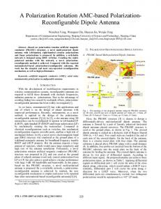
I. INTRODUCTION Since the first commercial developments of cellular communications, multiple parts of the spectrum have been absorbed by the ever growing demand of cellular systems. In the sub-GHz range more than 10 different frequency bands have already been defmed by LTE-A standard (Fig. 1) and further bands will be added in the future as more spectrum will become available worldwide for next generation mobile communications technologies. As a result the number of frequency bands supported by cellular terminals is continuously increasing. Such multiband requirements, along with the need for backward compatibility with legacy standards, make the RF front-end highly critical. Traditionally, multimode multiband RF front-ends has been implemented by bringing together several PAs, filters and switches onto a dielectric substrate, forming the RF Front-End Module (FEM). In order to reduce the size and cost of the RF FEM, the concept of reconfigurable PA appears as a promising solution. Research activities are in progress to develop reconfigurable multimode multiband PAs (MMPA) covering several modes and frequency bands using a reduced number of PA lines-up [ 1]. The output matching network (OMN) is a critical part of such PA architecture and tunable matching networks (TMN) using RF MEMS [2] or BST capacitors [3] have been proposed as alternatives to the more traditional but bulky broadband approach. Using a reconfigurable matching
'
,
I
I
i 7�
I
I
I
�
�
�
�
't; • • • i • • ' �
�
i' • • i �
treQ, MHz
Fig. 1.
2G/3G/4G cellular frequency bands in the sub-GHz range
Recently, a reconfigurable MMPA module targeting 2G/3G/4G handset applications has been demonstrated using GaAs HBT power devices and discrete PIN diodes in a multichip technology [4]. The obtained results are very promising but the integration level still remains limited. In this work, a reconfigurable OMN for MMPA applications has been designed and implemented in a SOl CMOS process. The proposed circuit has four RF output ports, covers up to ten E UTRA frequency bands ranging from 700 MHz to 920 MHz and can provide two different low impedance levels «30hm) to a high efficiency SOl MMPA.
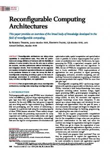
II. RECONFIGURABLE MATCHING NETWORK SOl CMOS technology offers today new opportunities for high efficiency MMPA integration [5]. MMPA design brings serious challenges since different output power and linearity requirements must be addressed on multiple frequency bands. To get optimum MMPA performances, the output matching network has to present optimal load impedance to the power stage. This optimal load impedance depends on the required output power and targeted linearity. With a 3.3 V supply, optimal load impedance at fundamental frequency for a reconfigurable SOl LDMOS MMPA is 2 Ohm (Ropt_sat) in saturated mode and 3 Ohm (RopUin) in linear mode. Fig. 2 shows the simulated performances obtained at 900 MHz with a load impedance of Ropt_sat in saturated mode (left) and RopUin in linear mode (right).
978-1-4799-8275-2/15/$31.00 ©2015
IEEE
Maximum efficiencies of 80% and 50% are obtained in saturated (CW signal) and linear (20 MHz LTE signal) modes respectively.
B.
Design
L-C section of each path is designed to realize optimal load impedance at the central frequency of the active path, using classical impedance transformer equations. Depending on the targeted impedance and frequency band, series inductance ranges from l.7 nH to 2.7 nH and shunt capacitance ranges from 14 pF to 19 pF, as shown in Fig.4. 2.8n 2.60
PouIldBm)
� �
PoutldSm)
Fig. 2. MMPA efficiency (PAE) and power gain (Gp) in saturated mode (left) / MMPA efficiency (PAE) and linearity (ACLR) in linear mode (right)
A. Architecture
,
I
" �-:'
,
,
:: [�;:: :
,, , , ,
, , ,
L3
'
I
Vsw_serie �
, ,
nFET
I
... -------- ..
' ... _---------/
LO L2
L-���� �'--7-,��� P2 3G/4G (B5,B6,B13,B14, B18,B19,B20)
Ropt
Sat
20hm
lin
30hm
Ll
PI
2.4n
--
2.2n
L·
1.8n
(VO=
Ropt
�� ������� � I (:�__--___-___-�,
--
2.On
1.60
.
--
---
--
- - - - - - - - - --- RopUin
1B.p
0 :l.
17.p
�
1S.p
(j 60. Table II summarizes the [mal inductance and capacitance values of the reconfigurable OMN obtained after co-design of the different RF paths. TABLE II .
Fig. 6. Maximum voltage across off-state shunt (bot) and series (top) switches vs load VSWR With a load VSWR of 5: 1, the maximum voltage across series and shunt switch can go up to 25V as shown in Fig. 7. To handle such high RF voltage, adequate number of NMOS devices must be stacked. Number of stacked NMOS devices (Nsw) in series and shunt switches are given in Table I.
0.7
0.6
Wswitch
_=====jP2 __
�=EOJ
.
. . .
.
LO
Ll
L2
L3
Cl
C2
C3
C4
1.8n
LIn
0.6n
O.Sn
ISp
12.5p
10.5p
ISp (BS) 12p (B8)
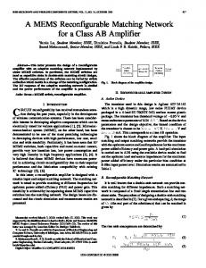
Fig. 9 shows the simulated input matching (with a reference impedance of 3 Ohm for path PI, P2, P3 and 2 Ohm for path P4) and insertion loss obtained with these values. -5
30
-10 __
25
m
-15
2: 20
u;
-20
�
:!:!.
15
-25
10
-30
o
1.6
PI
P2
P3
P'
m
1.2
0 ...J c 0
0.8
�
Maximum voltage across off-state shunt and series Fig. 7. switches for a VSWR of 5: I
�
'"
.£
TABLE I
1.'
:!:!.
1.0 0.6 0.4 0.2 0.0 0.65
0.70
0.75
0.60
0.65
0.90
0.95
1.00
Frequency (GHz)
Nsw(serie)
8
8
8
7
Nsw(shunt)
5
7
8
8
Fig.9. Simulated SII (top) and insertion loss (bot) of paths PI (circle), P2 (square), P3 (diamond) and P4 (band 5- triangle / band 8 - inverse triangle) when in on-state
978-1-4799-8275-2/15/$31.00 ©2015
IEEE
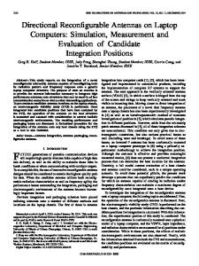
III. EXPERIMENTAL RESULTS The proposed circuit occupies an area of 1.5 mm2 including pads, negative voltage generator and control interface (SPI). All capacitors and RF switch are integrated into a SOl CMOS 130 nm process with high resistivity substrate. Series inductors L2 and L3 are implemented on chip whereas input inductor LO and inductor Ll are realized using bondwires to get higher Q (>50). Fig. 10 shows a photograph of the reconfigurable OMN and the measured insertion loss (lL) for the different modes and bands. 1.8
en en 0 ....J c 0
�en .£
TABLE III
This work
[3)
4
1.9+j1 to 2.7+jO.7
1.1 to 1.7
1.5
700-920
3.4·j1.9 to 3.6 4.3 to 4.3+j1
1.4 to 1.6 1.8 to 2.1
55
820-920 1700-2000
Currently fixed output matching network losses, including modelband switch, are usually in the range of 0.5-0.8 dB in the 700-920 MHz frequency range. Measured IL of the proposed reconfigurable OMN is higher than these requirements but retro-simulations show that it can be reduced by optimizing circuit layout.
1.6
[i) �
The obtained results are compared in Table III with a BST based solution for quad-band 2G/3G applications [3]. The proposed solution offers comparable measured IL with a higher transformation ratio and a much lower occupied area.
1.4 1.2 1.0 0.8 0.6
IV. CONCLUSION
0.4 0.2 0.0 0.65
0.75
0.70
0.80
0.85
0.90
0.95
1.00
Frequency [GHzl
Fig. 10. Measured insertion loss of paths PI (circle), P2 (square), P3 (diamond) and P4 (band 5- triangle / band 8 - inverse triangle) when in on-state Measured IL is higher than expected but remains lower than l.7 dB. Measured input impedance at 835MHz is l.9 + jl.0 and 2.4 + jO.50hm in saturated and linear mode respectively. Good agreement is obtained between measurement and simulation as shown in Fig. 1 1.
A SOl CMOS reconfigurable matching network for MMPA applications has been designed, implemented and tested. The obtained results are promising and compare favorably to the state-of-the-art, with a higher integration level. Future design with reduced loss «ldB) and silicon area are expected by using advanced SOl CMOS process with thick copper back end.
REFERENCES
[1]
[2]
E
[3]
E
� ,&
� "
[4]
P4 E
active (BS)
E
�
� ,&
Ireq, Hz
[5]
Unha Kim; Sungyoon Kang; Jungrin Woo; Youngwoo Kwon; Junghyun Kim, "A Multiband Reconfigurable Power Amplifier for UMTS Handset Applications," Microwave Theory and Techniques, IEEE Transactions on , vo1.60, no. 8, pp.2532-2542, Aug. 2012 A. Fukuda, T. Furuta, H. Okazaki, S. Narahashi, T. Nojima, "Low-Loss Matching Network Design for Band-Switchable Multi-Band Power Amplifier," IEICE Trans. Electron., vol. E95-C, no. 7, pp. 1172-1181, Jul. 2012. A. Tombak, "A ferroelectric-capacitor-based tunable matching network for quad-band cellular power amplifiers," IEEE Trans. Microwave Theory and Techniques. vol. 55, no. 2, pp. 370-375, Feb. 2007. S. Kang, U. Kim, J. Kim, "A Multi-Mode Multi-Band Reconfigurable Power Amplifier for 2G/3G/4G Handset Applications," IEEE Microwave and Wireless Components Letters, Oct. 2014 A.Giry, "SOl CMOS PA for Mobile Applications," in IEEE MTT-S Int. Microw. Symp., Workshop WSA, Tampa, Jun. 2014
freq, Hz
Fig.lI. Measured (solid line) and simulated (dot line) input impedance (circle: real part - square: imaginary part)
978-1-4799-8275-2/15/$31.00 ©2015
IEEE