different datasets, apply parallel operations on data, create analysis templates, and how this ... In addition, we need rapid application development tools for.
A Spreadsheet Framework for Visual Exploration of Biomedical Datasets Sofiane Sarni, Anderson Maciel, Ronan Boulic, Daniel Thalmann Virtual Reality Lab (VRlab) Ecole Polytechnique Fédérale de Lausanne (EPFL), 1015 Lausanne, Switzerland {Sofiane.Sarni, Anderson.Maciel, Ronan.Boulic, Daniel.Thalmann}@epfl.ch
Abstract In this paper, we present our spreadsheet framework, which uses a spreadsheet-like interface for exploring biomedical datasets. The principles and advantages of this class of visualization systems are illustrated, and a case study for the analysis of hip joint congruity is presented. Throughout this use case, we see how end users can compare different datasets, apply parallel operations on data, create analysis templates, and how this helps them in the exploration process.
1. Introduction With the increase in computer power, more and more effort is being dedicated for building more realistic computational and graphical models to be used in clinical applications [1, 2]. This effort is important but is not sufficient in itself since end users (clinicians) need tools that can effectively help them in performing the regular tasks they are used to. Such tasks include diagnosing, planning and analyzing interventions. They are in general done visually, based on images like MRI, CT, Ultrasound, reconstructed volumetric or surface models and other derived functional models. Resulting biomedical datasets can be multi-dimensional and are usually very large, which makes them difficult to explore and understand [3]. Therefore there is a need for intuitive representations for end users to deal with the increasing complexity of biomedical datasets. In addition, we need rapid application development tools for building those representations. Most medical visualization systems [4, 5] are based on the general flow chart paradigm [6]. Flow chart visualization systems are typically used for data visualization and are widely available as commercial products. In these systems, users select processing modules and wire them together into a pipeline. A common problem with flow chart visualization systems is that they spend the most part of their screen on operators and their interconnections. To deal with this problem another class of visualization systems was introduced: spreadsheet-like interfaces. Spreadsheet-like interfaces are a generalization of conventional spreadsheets where cells can contain graphical objects such as images, volumes, or animations or even widgets to interact with data [7]. Screen space is spent on operands rather than operators, which are usually more interesting to the end user [8]. They also benefit from the fundamental properties of spreadsheets, which makes it easy to organize, compare, analyze and perform operation on data. Despite those advantages, the state of the art shows no significant medical application apart from some illustrative examples [9]. We developed a spreadsheet framework, which uses a spreadsheet-like interface, and used it to explore biomedical datasets.
The reminder of this paper is organized as follows. The principles of the framework are presented in section 2. In section 3, an example of construction shows how to build a spreadsheet step-by-step. Section 4, presents a use case for the analysis of hip joint congruity.
2. The spreadsheet framework The spreadsheet framework consists basically of the following elements: cells, operators and dependencies. Cells are the basic data elements. A cell can contain numbers, images (2D or 3D), curves, vectors or matrices. They can also contain display widgets or control widgets for interactive cells (for example, sliders to control opacities for volumetric data). A list of supported cells is presented in Table 1. The cells are organized in a tabular layout and referenced by row and column, which makes them easy to browse. References can be relative or absolute, which helps in quickly constructing complex spreadsheets by moving cells or simply through copy and paste. Operators are applied to cells or ranges of cells, and results are stored in cells. These operators define the dependencies between the cells. Dependencies - A firing algorithm controls dependencies as in conventional spreadsheets. This algorithm keeps track of dependencies between cells and automatically updates the cells to reflect changes. Dependencies are recorded in a directed graph pointed from reference cells to depending cells. The framework is implemented in C++, uses the VTK library [10] for rendering and filtering capabilities, and Trolltech’s QT for Graphical User Interface [11]. These libraries, being portable, facilitate migration of the environment to other platforms. Type Data Display widgets Control widgets
Cells Scalar, Vector, Matrix, List, Volume, Mesh, Image, Color, ColorMap, Text, Loader, Importer, Exporter, vtkDataset, vtkSource Label, Renderer, ImageViewer, Plotter Button, Slider, AnimController, ComboBox, Radio, Checkbox
Table 1. Type of cells supported in the framework.
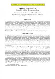
3. An example of simple construction A step-by-step example is given in this section in order to show how a spreadsheet can be constructed. In this example, we want to view volumetric data coming from MR images. Cells can be edited alternatively by a command line or graphically through property windows. In Figure 1, to load the MR data, we start by creating a data loader in cell A1: A1 = loader
A button is associated with this data loader to change datasets. Then, we create an image viewer in B2. We define the data source giving the loader A1 as argument: B2 = imageviewer A1
After that, we create a slider widget to be used for selecting the slice being viewed in B2. A name is given for the widget (“slice”) and the number of steps is linked to the number of slices in the data source A1: B1 = slider –name "Slice" –steps A1.nSlices
We have also to tell B2 that the slice to be viewed is given by the slider in B1: B2.currentslice = B1
Finally, we create a color map in A2 and associate it with the image viewer: A2 = colormap "grayscale" B2.colormap = A2
The resulting spreadsheet and dependencies graph is shown in Figure 1. The spreadsheet can now be interactively used to explore MR volumes by loading different datasets (A1), browsing slices (B2) and changing color maps (A2). A
1
Loader
B nSlices
source
2
ColorMap
Slider
currentslice
ImageViewer colormap
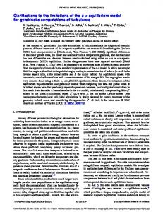
Figure 1. Example of construction of a spreadsheet for volumetric MR data exploration. The dependencies graph is shown on the right. This dependencies graph can also be seen as an equivalent flow chart diagram. We continue with our example to see how we can benefit from the tabular organization of cells to create analysis templates. We want to compare between different color mappings for viewing the slices. For this, we add a new row (3). This row can be created from zero but it is more interesting to use relative references in the previously constructed row (2) and simply copy and paste this row as a new one in (3). B2 = imageviewer $A$1 – currentslice B$1 – colormap $A2
We use the same notation as in Microsoft Excel [12] for referencing cells. The source for B2 is given by an absolute reference $A$1. If cell B2 is moved or copied elsewhere it will always take its data from the cell A1. While in the reference for the color map reference, only the column is considered absolute ($A1), which means that the color map will be considered as situated on the same row but always in column A. Copying row 2 and pasting it into row 3 creates new cells with correct references. Figure 2
shows the results. We used the same approach to extend the spreadsheet to the right.
A
B
C
1
Loader
Slider
AnimController
2
ColorMap
ImageViewer
ImageViewer
3
ColorMap
ImageViewer
ImageViewer
Figure 2. Example showing advantages of tabular layout and relative references. Row 2 was copied into row 3. Then, column B was copied into column C. The slider in B1 was replaced by an animation controller in C1. This controller allows to animate the slices in column C by cycling through the slices. On the right, dependencies graph with elements created with copy/paste in dashed lines.
4. A concrete case study: contact area estimation in the hip joint In the context of this paper, the explored data come from the biomechanical simulation of the human hip joint. Separated software, based on a conceptual joint model is used for hip simulation [13]. The model is based on a hybrid approach. A kinematical component defines the bony rigid motion from measures on the static and dynamic MRI, while a biomechanical component computes soft connective tissues deformation, and allows estimating force exchange and consequent stress on those soft structures. Both soft and hard tissues are geometrically represented by b-rep in the form of 3D meshes reconstructed from MRI analysis, which are used for visualization and collision detection. In addition, soft parts are discretized such that a generalized massspring system can process the deformations. Special considerations had to be taken into account to adapt traditional mass-spring system to medical applications. The most important is the correct biomechanical behavior of the biomaterials. In a previous work [14], we describe how we configure our springs lattice such that our virtual ligaments and cartilages have a predictable elasticity, defined by the Young’s Modulus (E) of the material. Other material properties are also considered, like anisotropy, viscoelasticity, permeability and so on, but are less relevant for the application presented in this paper. A hip model has then been built to illustrate a use case where the joint congruity is analyzed. The elements present in our hip are: the femur and the pelvis bones; the femoral head and the pelvis cup cartilages; the ischiofemoral ligament; the acetabular rim (labrum). The bones and the labrum are considered rigid, and the elasticity for the cartilages and ligament is defined to be 10 kPa. It is softer than the mean value found on the literature, but it allows our simulation to converge faster, while the stress distribution remains coherent. In addition, fibers orientation is taken into account for the ligament, in a way that it is anisotropic. The motion we performed is 90° of flexion plus total internal rotation, a key motion in Orthopedics.
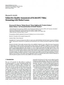
Figure 3. A template comparing different contact area estimations on the hip joint cartilage. The contact area is estimated based on the stress calculated on the cartilage surfaces. A stress threshold was defined in A2 and used to determine the contact area on the 3D animation in B2. Other views were derived (C2 and D2) and a plot of the contact area history is shown in E2. The row 2 was then copy-pasted into rows 3 to 5. Finally, different thresholds are chosen and the contact area changes propagate into the remaining cells. A template comparing different contact area estimations for this motion is shown in Figure 3. The motion simulation, including deformation and stress calculation is done offline (because it takes about 10 minutes to process in a standard computer) and produces an animation dataset. The animation dataset, containing all displacements and stresses along time, is then loaded and played into a cell of the spreadsheet, where it is combined with other cells to define operations and views. The threshold slider in column A (Figure 3), for example, determines different estimated contact area and consequent color distribution for each row of the sheet. Users can also use transparency to inspect internal parts that are usually masked in the 3D views.
5. Conclusions We have developed a framework based on a spreadsheet-like interface to be used in visual exploration of biomedical datasets. We took a hip joint motion simulation as a use case to illustrate the potentialities of our framework.
Besides all the advantages known about conventional spreadsheet interfaces (creating analysis templates, applying operations in parallel), we can mention some that have shown to be very relevant in the context of medical applications. Medics do not care about the data operations, they are more interested on the data itself, and that is the heart of spreadsheet interfaces. Medical data being multidimensional are easily understood due to the tabular organization of the interface, which reduces data dimensionality. It helps in creating a coherent mental model. Comparing different visual representations and modifying the parameters that make them different at the same time allows clinicians to isolate and focus on the interesting features and discard less useful views, as in the case study of section 4. That allows clinicians to gain time on diagnosis. Conclusions can also be drawn about our hip joint model development. The possibility of easy comparison and parameterization offered by the spreadsheet highlight the weak points of the model allowing us to correct them. It also aids in identifying the biomechanical features playing a key role on the medical problematic, guiding the researcher on the task of simplifying the model while keeping it medically useful.
6. Acknowledgment This work was supported by the Swiss National Science Foundation in the framework of the NCCR CO-ME. We thank Dr. Hassan Sadri, MD, from the Orthopedics Department of Fribourg Hospital for his support with the simulation of the hip joint.
7. References [1] A. Aubel, and D. Thalmann, “Interactive Modeling of Human Musculature”, Proc. Computer Animation 2001, Seoul, Korea, November 7–8, 2001. [2] F. Scheepers, R. E. Parent, W. E. Carlson, and S. F. May, “Anatomy-Based Modeling of the Human Musculature”, SIGGRAPH’97, 1997, pp. 163–172. [3] I. S. Lim, P. H. Ciechomski, S. Sarni, D. Thalmann, “Planar Arrangement of High-dimensional Biomedical Data Sets by Isomap Coordinates”, In. Proc. Of the 16th IEEE Symposium on Computer-Based Medical Systems (CBMS 2003), June 26–27, 2003, New York, pp. 50–55. [4] Amira form Mercury Computer Systems, http://www.amiravis.com, last accessed April 5th, 2005. [5] Rymon-Lipinski B., Jansen T., Hanssen N., Lievin M., Keeve E., "A Software Framework for Medical Visualization", In Proc. of IEEE Visualization '02, Boston, MA, October 27 - November 01, 2002. [6] P. E. Haeberli, “ConMan: A Visual Programming Language for Interactive Graphics”, In Computer Graphics (SIGGRAPH’88 Proceedings), ACM Press, volume 22, pp. 103–111, 1988. [7] E. H. Chi, P. Barry, J. Riedl, and J. Konstan. “A Spreasdheet Approach to Information Visualization”, In Proc. IEEE Symposium on Information Visualization '97, Phoenix, Arizona, IEEE CS Press, pp. 17–24. [8] M. Levoy, “Spreadsheets for Images”, In Computer Graphics (SIGGRAPH '94 Proceedings), Orlando, Florida, July 24-29, 1994, ACM Press, volume 28, pp. 139–146. [9] T. J. Jankun Kelly, K.-L. Ma, and M. Gertz, “A Model for the Visualization Exploration Process”, In Proc. 13th IEEE Visualization 2002, Boston, MA, U.S.A., October 27 - November 1, 2002, IEEE CS, pp. 323–330. [10] W. Schroeder, K. Martin and B. Lorensen, The Visualization Toolkit, 2nd Ed., Prentice Hall PTR, 1998. [11] M. K. Dalheimer. Programming with QT, 2nd Edition. O’Reilly. March 2002. [12] Microsoft Corporation. Microsoft Excel language reference. Microsoft Corporation, 1997. [13] S. Sarni, A. Maciel, R. Boulic, D. Thalmann, “Evaluation and Visualization of Stress and Strain on Soft Biological Tissues in Contact”, In Proc. of International Conference on Shape Modelling and Applications, Genova, Italy, June 7-9, 2004, IEEE Computer Society Press, Los Alamitos, 2004, pp. 255–262. [14] A. Maciel, R. Boulic and D. Thalmann, “Deformable Tissue Parameterized by Properties of Real Biological Tissue”, In Proc. International Symposium on Surgery Simulation and Soft Tissue Modeling, 2003, Juan-lesPins, France, Springer-Verlag, Berlin, 2003, pp. 74–87.